Table of Contents
Advertisement
Advertisement
Table of Contents

Related Manuals for Christie Spyder X20

Summary of Contents for Christie Spyder X20
- Page 1 User Manual 020-000916-01 Spyder X20...
- Page 3 User Manual 020-000916-01 Spyder X20...
- Page 4 Projector lamps (See Christie’s separate lamp program policy). Problems or damage caused by use of a projector lamp beyond the recommended lamp life, or use of a lamp other than a Christie lamp supplied by Christie or an authorized distributor of Christie lamps.
- Page 5 ENVIRONMENTAL The product is designed and manufactured with high-quality materials and components that can be recycled and reused. This symbol means that electrical and electronic equipment, at their end-of-life, should be disposed of separately from regular waste. Please dispose of the product appropriately and according to local regulations.
- Page 6 China RoHS Compliance Information 关 于中国 《电子信 息产品 污染控制 管理办 法》的说 明 • Environmentally Friendly Use Period 环 保使用 期限 The year number in the centre of the label indicates the Environmentally Friendly Use Period, which is required to mark on the electronic information product sold in China according to the China RoHS regulations.
- Page 7 Addendum Translated copies of this document are provided on the CD in the back of this document. The CD may also contain additional product documentation. Read all instructions before using or servicing this product. 本文 档 的 翻 译 副本在本文档背面的 CD 上提供。该 CD 中还可能包含其他产品文档。使用或 维修...
-
Page 8: Table Of Contents
KeyFrame Manipulation ......................34 Borders .......................... 35 Shadows ......................... 35 Clones ..........................35 Cropping ......................... 36 Pan and Zoom ......................... 36 Standard and Custom Shapes ................... 36 Layer Test Patterns ......................40 Spyder X20 User Manual 020-000916-01 Rev. 1 (04-2016) - Page 9 Stereoscopic (SSO) ......................61 User Diagnostics ................. 62 Real-Time Protection ......................62 Real-Time Protection Alerts ....................62 Configuring Real-Time Protection ..................62 User Diagnostics Viewer ....................... 63 Hot-Sync ..................65 Options for Hot-Sync ......................65 Spyder X20 User Manual 020-000916-01 Rev. 1 (04-2016)
- Page 10 (4 x 2) PixelSpace Sample Configuration ................93 (4) projector Blend with Rotated flanking displays ............... 98 (8) projectors EdgeBlend and Rotated ................101 Working with Mullions (Dead Space for Fluid Window Fly’s) ..........103 Troubleshooting ........................ 105 Spyder X20 User Manual 020-000916-01 Rev. 1 (04-2016)
- Page 11 FIX: Application Crashes Related to DirectX ..............107 LAN Card Priority Setting Network Not found ..............107 Connecting to an X20 using remote.................. 108 Spyder X20 dual-link support ..................108 External Control Protocol ..............111 Serial Connectivity ......................111 Ethernet Connectivity ......................111 Command Overview Table ....................
- Page 12 Seamless Parallel Expansion Example .................. 157 Configuring the Frame Groups and their AOR ................ 161 Unrestricted Layers ......................162 Spyder X20 HDCP Functionality (Option) ..........164 Configuring HDCP Mode ..................... 168 Displaying HDCP Status in the UI ..................169 Output Status ........................169 Input Status ........................
-
Page 13: Overview
AMX or Crestron systems. These control systems are generally found in installations where Spyder is only one of several disparate systems combined to form a larger system. Spyder X20 User Manual 020-000916-01 Rev. 1 (04-2016) -
Page 14: Spyder System Introduction
Figure 1 depicts two defined PixelSpaces that exist within the VI, the first of which has a resolution of 3,496 x 1,050 pixels. Although this image is using only a portion of the available video space within Spyder, the Spyder X20 User Manual 020-000916-01 Rev. 1 (04-2016) - Page 15 29.97 13,200,000 8,200,000 7,900,000 59.94 6,600,000 Figure 3: Spyder VI size at various frame rates (200/300 Series) Frame Rate (Hz) Pixels Available NTSC 20,000,000 20,000,000 23.98 20,000,000 20,000,000 20,000,000 29.97 20,000,000 20,000,000 Spyder X20 User Manual 020-000916-01 Rev. 1 (04-2016)
- Page 16 20,000,000 20,000,000 20,000,000 Figure 4: Spyder VI size at various frame rates (X20 Series) Note: The physical input and output module count in Spyder has no effect on the internal VI size. Spyder X20 User Manual 020-000916-01 Rev. 1 (04-2016)
-
Page 17: Installing Vista Advanced
The Vista Advanced software is provided as part of the ‘Spyder Control Suite’ software package, which is included with the shipment of the Spyder system on a discus drive. Software updates are released regularly, and can be obtained from the Christie web site. Contact Christie technical support at: http://www.christiedigital.com/en-us/product-support/support-offices/Pages/default.aspx Follow the procedure below to install the Vista Advanced software on your computer. -
Page 18: Advanced Client Configuration
The use of complex routers and managed switching equipment is not recommended. Communication interruptions are possible if these devices are not configured properly. 4. Temporary disruptions in network connectivity may cause a loss of communication with Spyder. Spyder X20 User Manual 020-000916-01 Rev. 1 (04-2016) - Page 19 If the connection between Spyder and its client(s) are interrupted, it is possible for the communication socket to break. This would cause a temporary loss of communication until the socket is restored by restarting the client application. Spyder X20 User Manual 020-000916-01 Rev. 1 (04-2016)
-
Page 20: Getting Started With Vista Advanced
‘Update Now’, and a dialog appears when connecting to the frame requesting confirmation to update the Spyder frame firmware to match the client version. Figure 5 shows the firmware update confirmation dialog. Spyder X20 User Manual 020-000916-01 Rev. 1 (04-2016) -
Page 21: User Interface Introduction
Sources: The source list contains all user-defined video inputs connected to Spyder. Users can click sources in the list to view source properties, or can drag individual sources to other panels to apply sources to layers or scripting elements. Spyder X20 User Manual 020-000916-01 Rev. 1 (04-2016) - Page 22 Dynamic help describes the object clicked on by a user, and provides additional tips and tricks to get the most from the Advanced interface. Spyder X20 User Manual 020-000916-01 Rev. 1 (04-2016)
-
Page 23: Modifying The Panel Layout
Figure 7 below shows the various available docking handles. If the mouse is released while not over a dock handle, the panel will become undocked. Spyder X20 User Manual 020-000916-01 Rev. 1 (04-2016) - Page 24 The drop icon in the center of the control specifies a ‘tab’ dock, and is useful for putting several infrequently controls into the same space and tabbing between them as needed. Spyder X20 User Manual 020-000916-01 Rev. 1 (04-2016)
-
Page 25: Saving And Recalling Panel Layouts
Advanced for the first time. This layout cannot be edited by the user, and can be used to restore the layout of the Advanced application to its factory default at any time. Spyder X20 User Manual 020-000916-01 Rev. 1 (04-2016) -
Page 26: Getting Started
2. The second page of the welcome screen displays a list of eight (8) frame selectors with associated IP addresses, as shown in Figure 10. The IP Address of every Spyder frame on the network will appear in Spyder X20 User Manual 020-000916-01 Rev. 1 (04-2016) - Page 27 IP Address in the adjacent dropdown control. At the bottom of the frame rate selection screen, select the desired frame rate for the Spyder system before clicking ‘Next’. Figure 10: Configuration Manager frame selection Spyder X20 User Manual 020-000916-01 Rev. 1 (04-2016)
- Page 28 Note that an operator’s monitor can only be assigned on an unused universal output; DX4 output modules do not support operator monitor modes. Spyder X20 User Manual 020-000916-01 Rev. 1 (04-2016)
-
Page 29: Working With Sources
In addition to adding a source, an existing source may be deleted, or a new source space may be inserted. You may also copy an existing source to allow the user to have multiple input configurations to the same source. Spyder X20 User Manual 020-000916-01 Rev. 1 (04-2016) -
Page 30: Working With The Sources List
Right click the source and select ‘Exit configure source’ to exit configuration mode. Source Properties Panel When an existing source is selected from the source list, a context sensitive panel appears displaying properties specific to the selected source. Spyder X20 User Manual 020-000916-01 Rev. 1 (04-2016) -
Page 31: Configuring A New Source
(HD15, DVI, and so on). In the Router section provide a name for the router and the input number for this source. [If no router is used, use the Router selection combo box to select “Direct to Layer” or select the Remove link to remove the router]. Spyder X20 User Manual 020-000916-01 Rev. 1 (04-2016) - Page 32 – see previous screenshot above<<provide figure number>>). 6. Fill in the input configuration information (part will already be auto filled). [Use the Autosync button to automatically detect the type and properties of the video source.] Spyder X20 User Manual 020-000916-01 Rev. 1 (04-2016)
-
Page 33: Input Keyer Modes
Spyder X20 User Manual 020-000916-01 Rev. 1 (04-2016) -
Page 34: Keyframe Manipulation
The height of the layer is calculated based on the aspect ratio of the source, and so a height value is not provided within the KeyFrame properties. Spyder X20 User Manual 020-000916-01 Rev. 1 (04-2016) -
Page 35: Borders
The adjustment range is from 0 (black) to 255 (transparent). Clones A Clone is a ‘free’ duplicate copy of a layer. As the name suggests, a clone will share all KeyFrame properties with the original layer such as Spyder X20 User Manual 020-000916-01 Rev. 1 (04-2016) -
Page 36: Cropping
Standard and Custom Shapes A custom shape can be added to a source or a still. Spyder X20 User Manual 020-000916-01 Rev. 1 (04-2016) - Page 37 Getting Started Start by bringing a source into preview. Select “Shape” from the Border/Shadow menu. Click on each shape to see a live preview of how it will look on the screen. Spyder X20 User Manual 020-000916-01 Rev. 1 (04-2016)
- Page 38 Getting Started Change the border thickness to 50 or higher. Spyder X20 User Manual 020-000916-01 Rev. 1 (04-2016)
- Page 39 Select a texture type. The textures appear real time as they are selected. The selected textures may not be a fit for the desired “look” so a custom texture can be applied. Spyder X20 User Manual 020-000916-01 Rev. 1 (04-2016)
-
Page 40: Layer Test Patterns
Layer test patterns are useful for troubleshooting purposes, and the test pattern section of the layer properties panel allows a user to specify a test pattern type as well as additional options such as grids and alignment circles. Spyder X20 User Manual 020-000916-01 Rev. 1 (04-2016) - Page 41 Load Standard/Load User Defined: Loads resolution rates to associate with the source. Use raster control to set the edges of a corresponding video input. If AutoDetect doesn’t work for “Sync Type,” manually enter sync type. Spyder X20 User Manual 020-000916-01 Rev. 1 (04-2016)
-
Page 42: Working With Still Images
Each of these will take time to load the still. When using a preview PixelSpace, loading a still into the preview PixelSpace and then transitioning to program is recommended. Spyder X20 User Manual 020-000916-01 Rev. 1 (04-2016) -
Page 43: Treatments
If a KeyFrame is already defined at the selected element cue, the treatment will be applied to the existing element KeyFrame properties. If no KeyFrame already exists at the specified location, a new KeyFrame will automatically be added to the element. Spyder X20 User Manual 020-000916-01 Rev. 1 (04-2016) -
Page 44: Using The Display Simulator
PixelSpace that might otherwise be obscured by another PixelSpace. DURATION: Sets the duration of the transition (in frames) for live layer transition operations such as mixing a layer on or off screen. Spyder X20 User Manual 020-000916-01 Rev. 1 (04-2016) - Page 45 This area displays all program PixelSpaces included in the current view stack. PREVIEW PIXELSPACE(S): If the Spyder system was configured to use preview PixelSpaces as part of initial configuration, a preview section of the simulator will appear, allowing for off-screen editing. Spyder X20 User Manual 020-000916-01 Rev. 1 (04-2016)
-
Page 46: Command Keys
RELATIVE: A relative command key affects only layers defined within the command key, and does not remove or otherwise modify any other layers on screen. Spyder X20 User Manual 020-000916-01 Rev. 1 (04-2016) - Page 47 Command Keys Figure 21: Layer Pattern Generator Spyder X20 User Manual 020-000916-01 Rev. 1 (04-2016)
-
Page 48: Scripting
‘Add KeyFrame’. When editing the KeyFrame of a layer defined as a script element, the ‘driving KeyFrame’ is automatically modified. Note: You can change the duration of the element on individual KeyFrames allowing you to adjust transition durations within the script. Spyder X20 User Manual 020-000916-01 Rev. 1 (04-2016) -
Page 49: Cue Triggers
BVW75 or Odetics. Refer to Required Hardware (page 67). To add a Trigger to a script cue, click on the cue within the script panel, and select a trigger type and Trigger length value on the properties panel. Spyder X20 User Manual 020-000916-01 Rev. 1 (04-2016) -
Page 50: Function Keys
1. Right Click in the Function Key section (make sure the Function Key tab is selected). 2. Select the desired Function Key type off from the contextual menu that appears. 3. Select the Function Key icon and enter the required information in the Properties section. Spyder X20 User Manual 020-000916-01 Rev. 1 (04-2016) -
Page 51: System Layout Grid
Right click an output to set as (source) configuration output and Operator’s Monitor overlay output (the same output can be used for source configuration and Operator’s Monitor overlay). When Operator’s Monitor overlay is selected, layer indicators are shown on your Operator’s Monitor. Spyder X20 User Manual 020-000916-01 Rev. 1 (04-2016) - Page 52 A DX4 output can be rotated. This rotation happens in the output and does not rotate a PixelSpace. This can be useful for tall and narrow displays such as LED walls. Spyder X20 User Manual 020-000916-01 Rev. 1 (04-2016)
-
Page 53: Alert Viewer
Alert Viewer to see if there is a noted problem or pattern. The Alert View information can be saved or a screen shot of the panel can be made for Christie support staff to better identify the cause of problems. -
Page 54: Devices
– and the device function can be run also. You can change the duration time of a mixer in the duration box in the upper left corner of the devices pane. Figure 23: Devices Panel Spyder X20 User Manual 020-000916-01 Rev. 1 (04-2016) -
Page 55: Edid Management
EDID information into a Spyder input, or verify Spyder input EDID against a known EDID data source. Each of the EDID manager operations are described in detail in the following sections. Spyder X20 User Manual 020-000916-01 Rev. 1 (04-2016) -
Page 56: Recording Edid Data From A Display Device
To prevent accidental overwriting the EDID data in a display device, the third descriptor block in the EDID packet is reserved to uniquely identify a Spyder input module. Before Figure 25: EDID Manager welcome screen Spyder X20 User Manual 020-000916-01 Rev. 1 (04-2016) -
Page 57: Verifying Spyder Input Edid
The verification process is very close to the EDID programming process; however the actual programming step is bypassed during the verification operation. Figure 26: Recording EDID Data TO VERIFY THE SPYDER EDID AGAINST A KNOWN DATA SOURCE Spyder X20 User Manual 020-000916-01 Rev. 1 (04-2016) - Page 58 EDID data to the EDID read from the input. When completed, a popup dialog appears indicating the success or failure of the verification process. Click ‘Next’ after all Spyder input modules have been verified to display the ‘Finished’ screen. Spyder X20 User Manual 020-000916-01 Rev. 1 (04-2016)
-
Page 59: License Management
Requesting a License The license request process generates a snapshot of one or more Spyder frames, which is used by Christie to generate a license file specifically for your Spyder system(s). The hardware snapshot is combined with customer information collected during the license request process to create a packaged license request file. This file must be emailed to techsupport-az@christiedigital.com for processing. -
Page 60: Installing A License
Christie. The steps below outline the process of installing a license file on a Spyder frame. INSTALLING A LICENSE FILE 1. Copy all license files obtained from Christie to a directory on the client PC hard drive. Do NOT rename or change the extension of the license files, or they will become invalid. -
Page 61: Available Options For Spyder
The item(s) listed below provide a brief introduction to the various license protected features for Spyder. For more information on any of the items below, or for information on purchasing one or more of the licensed options, contact Christie technical support at: http://www.christiedigital.com/en-us/product-support/support-offices/Pages/default.aspx... -
Page 62: User Diagnostics
Real-Time protection is enabled by default. Users can manually disable real-time protection entirely, or individual types of warnings can be suppressed. The Real-Time protection configuration dialog is available from the ‘Tools’ menu within Vista Advanced and Vista Basic. Spyder X20 User Manual 020-000916-01 Rev. 1 (04-2016) -
Page 63: User Diagnostics Viewer
INDIVIDUAL TEST STATUS: Shows overview of individual tests run on all applicable modules. PRINTABLE REPORTS: Drop down list of report views Figure 30: Verifying Spyder EDID available for diagnostic data. Spyder X20 User Manual 020-000916-01 Rev. 1 (04-2016) - Page 64 RESET ERROR COUNTERS: Clears any previous test results, including any error counters. REFRESH NOW: Runs all tests on each module in the system and immediately refreshes the form to display the results. Spyder X20 User Manual 020-000916-01 Rev. 1 (04-2016)
-
Page 65: Hot-Sync
HotSync in this configuration, it is not desirable to overwrite the router definitions specific to each backup system. In these scenarios the ‘Push Routers’ checkbox should be unchecked, preventing router definitions to be updated on the HotSync backup frame. Spyder X20 User Manual 020-000916-01 Rev. 1 (04-2016) -
Page 66: Apply Output Configurations
HotSync operations. Provided the output configurations have not changed on the primary system, it is typically not necessary to update the output configurations on the backup system(s) after initial configuration. Spyder X20 User Manual 020-000916-01 Rev. 1 (04-2016) -
Page 67: Video Playback
Playback device integration requires the use of SourceMaster. SourceMaster is a 1-RU (rack unit) product manufactured by Christie as an accessory device which connects to Spyder via Ethernet, and in turn connects to up to four (4) RS-422/485 serial-based playback devices. A maximum of two SourceMaster units can be placed on a single Ethernet network to control a total of eight (8) devices from a single Spyder system. -
Page 68: Getting Started
PlayItem will be listed in the PlayItems list with the specified name, and the property panel for Advanced will change to show the relevant properties for the newly created PlayItem. Figure 34: Adding a new PlayItem Spyder X20 User Manual 020-000916-01 Rev. 1 (04-2016) -
Page 69: Playitem Property Panel
If no clip is specified, no clip will be recalled when the PlayItem is cued. PLAYITEM CONTROL: Allows for quick manual control of the PlayItem, including controls to cue to XX seconds from the PlayItem out point. Figure 35: Router Property Panel Spyder X20 User Manual 020-000916-01 Rev. 1 (04-2016) -
Page 70: Configuring Video Playback Devices
The most common cause of this problem is the RS-232 / RS-422 port on SourceMaster being switched to RS-232. Check this setting on the back of SourceMaster to ensure it is set to RS-422. Spyder X20 User Manual 020-000916-01 Rev. 1 (04-2016) -
Page 71: Configuring Playitems
Checked items indicate that the associated deck is to be controlled as part of the PlayItem. At least one port must be checked for the PlayItem to be considered valid, and multiple decks can be selected for sync-roll operations. Spyder X20 User Manual 020-000916-01 Rev. 1 (04-2016) -
Page 72: Manual Playitem Control
PlayItem state. When a PlayItem is not currently running, the in-point and total running time (TRT) will be displayed in the PlayItem register. While the PlayItem is active, countdown Figure 39: PlayItem Properties Spyder X20 User Manual 020-000916-01 Rev. 1 (04-2016) - Page 73 10 seconds in this example). In this example, 9 seconds and 21 frames of RollOut remain before the decks associated with this PlayItem will be stopped. Figure 40: Register Display for each PlayItem State Spyder X20 User Manual 020-000916-01 Rev. 1 (04-2016)
-
Page 74: Scripting With Machine Control
Register List Controls ‘trigger’ property, which can optionally be set to a ‘Time’ value. When a script executes a cue with an associated time trigger, the Figure 43: PlayItem section of Cue Panel Spyder X20 User Manual 020-000916-01 Rev. 1 (04-2016) -
Page 75: Playitem Drag-Drop Operations In Script
Dragging a PlayItem to an unused area within the script grid will complete the same operations to the script cues as when dragging a PlayItem onto a script cue, and will additionally add a source element with the default source specified on the PlayItem (if defined). Spyder X20 User Manual 020-000916-01 Rev. 1 (04-2016) - Page 76 In addition to PlayItem play and cue commands being layer 1 generated, a source element has been created with the default source defined on the PlayItem. Figure 45: Dropping a PlayItem onto a Script Layer Spyder X20 User Manual 020-000916-01 Rev. 1 (04-2016)
-
Page 77: Still Server (X20 Only)
Spyder X20 product line to dramatically increase the speed of still image loading in the system. The still image server application works by connecting to the Spyder X20 with both an Ethernet and a DVI video connection. When a still image file needs to be loaded, the X20 sends the file (if needed) and control commands which instruct the still server to display the image on its DVI output. -
Page 78: Recommended Specification
Installing and Configuring the Still Server The still server application is available on the Christie web site, along with the latest release versions of the Vista Advanced software platform. While not always required, it is always recommended that the still server application software be updated at the same time as the Vista Advanced / X20 server software. - Page 79 The default delay value as of the time of this writing is 300ms. Figure 48: Sixteen stills loaded into layers using a still image server Spyder X20 User Manual 020-000916-01 Rev. 1 (04-2016)
-
Page 80: Sample Configuration
Vista Advanced Software. 1. Go to File New. The Vista Systems Configuration GUI will open. 2. Select “Start with new empty configuration” Spyder X20 User Manual 020-000916-01 Rev. 1 (04-2016) - Page 81 7. Set the resolution of your projectors under the output resolution Format Name drop down menu. This should match the native resolution of your projector for optimal image quality. http://en.wikipedia.org/wiki/Display_resolution 8. Set the Connection type to match your projector input type i.e. DVI, SDI, VGA. 9. Click Next. Spyder X20 User Manual 020-000916-01 Rev. 1 (04-2016)
- Page 82 We will be using the X20 internal router for this sample configuration so no router selection is needed. The X20 Internal Crosspoint Switcher will be used to route video. Spyder X20 User Manual 020-000916-01 Rev. 1 (04-2016)
- Page 83 Sample Configuration For this sample configuration we will be using a virtual X20. Configuring an X20 can be done offline in virtual mode so that full configurations can be created offline. Spyder X20 User Manual 020-000916-01 Rev. 1 (04-2016)
-
Page 84: Adding Background Images To The V.i. Canvas
Output 1 (Left Projector) and Output 2 (Right Projector) together comprise the main output PixelSpace. Output 3 is allocated for the “Preview” output. Adding Background Images to the V.I. Canvas By right clicking in the Preview (PVW) space a custom image or color can be selected. Spyder X20 User Manual 020-000916-01 Rev. 1 (04-2016) - Page 85 Sample Configuration Select an Image with sufficient resolution and the correct aspect ratio for your Pixelspace for optional image quality. Spyder X20 User Manual 020-000916-01 Rev. 1 (04-2016)
-
Page 86: Adding Input Sources
Adding Input Sources It will simplify things if you know which sources you want to connect to the Spyder. Creating a source list will simplify the input configuration. In this example we will connect: Spyder X20 User Manual 020-000916-01 Rev. 1 (04-2016) - Page 87 Pressing the Capture Key will create a custom Icon in the simulator by frame-grabbing the respective input source and creating an Icon of the representing the full input image. You can also select a custom icon to identify inputs graphically. Spyder X20 User Manual 020-000916-01 Rev. 1 (04-2016)
-
Page 88: Adding Sources To The Pixelspace
Note that odd numbered inputs are BNC and even numbered inputs are DVI connectors. Adding Sources to the PixelSpace After inputs have been configured the input source list should look something like this. Click on a source and it will highlight red. Spyder X20 User Manual 020-000916-01 Rev. 1 (04-2016) - Page 89 1 (Layer 1) to the Preview Pixelspace. Also note the yellow route patch and the yellow boarder around Source 1. The Yellow indicates that Source is in Preview. When you drag a new Source to preview a new router patch is created in the System patch. Spyder X20 User Manual 020-000916-01 Rev. 1 (04-2016)
-
Page 90: Automating Tasks With Scripts And Function Keys
In this example we will use a Function Key to automate the Mix Background function. Select the Function Key tab and then right click. Select Add Background Mix Key. You will be prompted to name the Function. Spyder X20 User Manual 020-000916-01 Rev. 1 (04-2016) - Page 91 Right Click on “Program” in the Script window. Select Keyframe. Select the “Back Mix” Function Key. Select Script Position 3 and Add an Additional Keyframe. Select “Jump Options” and make sure Cue 1 is selected. Spyder X20 User Manual 020-000916-01 Rev. 1 (04-2016)
- Page 92 Double Click on the Preview Cue (Cue Zero). Hit the spacebar The Cue Line will move down and execute the Keyframe “Back Mix” function. The GOTO 1 will execute the Keyframe mix with each spacebar press. Spyder X20 User Manual 020-000916-01 Rev. 1 (04-2016)
-
Page 93: Sample Screen Configurations
Sample Screen Configurations Sample Screen Configurations (4 x 2) PixelSpace Sample Configuration To create this Pixelspace using the Vista Advanced Configuration GUI. Start with new empty configuration. Spyder X20 User Manual 020-000916-01 Rev. 1 (04-2016) - Page 94 Change the Screen output from the default (3) to (4). Change the Vertical output from the default (1) to (2). Change the Horizontal Overlap from the default of (256 for edge blending) to (0). Click Next. Spyder X20 User Manual 020-000916-01 Rev. 1 (04-2016)
- Page 95 Sample Screen Configurations Select Frame Rate and click next. Click Next. Spyder X20 User Manual 020-000916-01 Rev. 1 (04-2016)
- Page 96 Sample Screen Configurations Click Apply to local PC now (Virtual Mode). Spyder X20 User Manual 020-000916-01 Rev. 1 (04-2016)
- Page 97 1080 3856 1080 5784 1080 The Pixelspace is now configured and ready to use. Note that the yellow boxes are each graphically representing which area of the screen they are contributing to. Spyder X20 User Manual 020-000916-01 Rev. 1 (04-2016)
-
Page 98: Projector Blend With Rotated Flanking Displays
Sample Screen Configurations (4) projector Blend with Rotated flanking displays To create a four projector blend with a 300 pixel overlap and two rotated displays using the Advanced GUI. Start with new empty configuration Spyder X20 User Manual 020-000916-01 Rev. 1 (04-2016) - Page 99 Select Rotation 90 degrees since this is the left most rotated display. Click next To add the Widescreen 1. Click Add Additional Widescreen 2. Click the Widescreen PixelSpace to reveal the Properties. Spyder X20 User Manual 020-000916-01 Rev. 1 (04-2016)
- Page 100 4. Click next. 5. One the next two screens click next and then Apply to local PC (Virtual Mode). The System Patch graphically displays how the screens are allocated in the V.I. Spyder X20 User Manual 020-000916-01 Rev. 1 (04-2016)
-
Page 101: Projectors Edgeblend And Rotated
Sample Screen Configurations (8) projectors EdgeBlend and Rotated To create this Pixelspace using the Vista Advanced Configuration GUI. 1. Start with a new empty configuration. Spyder X20 User Manual 020-000916-01 Rev. 1 (04-2016) - Page 102 Change the Horizontal Overlap from the default of (256 for edge blending) to (216). 7. Change the rotation setting to 90 Degrees. 8. Click Next. 9. On the next two screens click next and then Apply to local PC (Virtual Mode). Spyder X20 User Manual 020-000916-01 Rev. 1 (04-2016)
-
Page 103: Working With Mullions (Dead Space For Fluid Window Fly's)
Sample Screen Configurations Working with Mullions (Dead Space for Fluid Window Fly’s) Spyder X20 in Parallel When there is the need to expand beyond 20 megapixels or eight outputs for a single conclusive system the X20 is capable of running in a mode called ‘parallel’. When the X2Os are in this mode each X20 has its area of responsibility, called AOR, in which sources that are required to be shared between AORs use an input from each X20. - Page 104 Frame Group is used. An upstream matrix switcher will automatically assign the same source in both the A and B layers and the system will automatically assign the slave layer when required. Spyder X20 User Manual 020-000916-01 Rev. 1 (04-2016)
-
Page 105: Troubleshooting
2. Enter the existing know IP address of the X20 frame in the Computer: field and click Connect. You should see a generic Windows login screen appear. The login and password for the Spyder frame is Cricket and Cricket. Spyder X20 User Manual 020-000916-01 Rev. 1 (04-2016) -
Page 106: Using X20 For Configurations With A Tall Vi
X20 frames can be operated in parallel to achieve the desired height. When a configuration exceeds 1860 pixels, the system will restrict which layers are able to accept stills. This also has an effect on which layers Spyder X20 User Manual 020-000916-01 Rev. 1 (04-2016) -
Page 107: Fix: Application Crashes Related To Directx
To do this, navigate to the Network settings on the client PC and access Properties for the LAN network adapter. Access the TCP/IPv4 properties for LAN network adapter and at the normal screen for entering the IP settings Spyder X20 User Manual 020-000916-01 Rev. 1 (04-2016) -
Page 108: Connecting To An X20 Using Remote
Password: Cricket Spyder X20 dual-link support Overview Certain inputs and outputs of the Spyder X20 will support 2560x1600@60Hz or up to 330MHz***. This document discusses the capabilities of the individual inputs and outputs. Inputs All of the X20 DVI inputs can support dual link resolutions, however because of the extreme bandwidth requirements, the preceding analog input connector is disabled while the dual-link source is in use. - Page 109 When a dual-link source is being used on layer 1, layer 2 will be used as well. This is shown in the simulator by a 1/2 in the layer label in the upper left corner. Spyder X20 User Manual 020-000916-01 Rev. 1 (04-2016)
- Page 110 Sample Screen Configurations Outputs The Spyder X20 will support dual-link resolutions on odd numbered outputs. Example: Outputs 1, 3, 5, and 7 will support dual-link. Spyder X20 User Manual 020-000916-01 Rev. 1 (04-2016)
-
Page 111: External Control Protocol
External Control Protocol External Control Protocol The Spyder / Spyder X20 frame uses an ASCII based command system for external control. Connectivity is available via an RJ-45 (Ethernet) connection, or a 9-pin RS-232 serial connection to the frame. Both the Ethernet and Serial interfaces respond to the same string commands, and can do so concurrently. - Page 112 Note: Some commands listed display argument(s) with an asterisk. These options are optional; however no further arguments may be entered in the command. Spyder X20 User Manual 020-000916-01 Rev. 1 (04-2016)
-
Page 113: Command Processor Responses
Argument 1: Configuration ID. This is the ID number to store the layer ID’s current input configuration to. Set the Configuration ID to -1 to force auto sync. Argument 2: The layer ID to apply the specified input configuration to. Spyder X20 User Manual 020-000916-01 Rev. 1 (04-2016) - Page 114 Command: KPS Argument 1: 0 = Absolute Position / 1 = Relative Position Argument 2: Horizontal Position Argument 3: Vertical Position Argument 4 ~ XX: Layer ID to set position Spyder X20 User Manual 020-000916-01 Rev. 1 (04-2016)
- Page 115 Argument 3: 0 = Load Next / 1 = Load Current Transition Background This command transitions the background layers across all PixelSpaces defined in the system. Note that it is not possible to transition individual PixelSpace backgrounds. Command: BTR Spyder X20 User Manual 020-000916-01 Rev. 1 (04-2016)
- Page 116 Argument 1: Router ID to switch. Argument 2: (L = Switch Logical Output, P = Switch Physical Outputs) Argument 3: Output to switch (Zero based). Argument 4: Input to switch to (Zero based). Spyder X20 User Manual 020-000916-01 Rev. 1 (04-2016)
- Page 117 Note that this command is mutually exclusive with the ‘Input Luminance Key’ command (above). If this command is used, luminance key will automatically be disabled. Spyder X20 User Manual 020-000916-01 Rev. 1 (04-2016)
- Page 118 This command will request the current execution cue of a specified script ID. Returns a single integer value representing the current cue of the specified script, or -1 if the specified script is not being executed on any layer. Command: SCR Argument 1: ID to request status for Spyder X20 User Manual 020-000916-01 Rev. 1 (04-2016)
- Page 119 This command will load an unscaled still image directly onto a Spyder output, for the purpose of loading custom test patterns. The file name specified must exist in the ‘Stills’ directory on the Spyder server, which can be accessed using FTP Spyder X20 User Manual 020-000916-01 Rev. 1 (04-2016)
- Page 120 KeyFrame will be used. Command: LCC Argument 1: Layer ID Argument 2: Clone Mode (0 = Off / 1 = Offset / 2 = Mirror) Argument 3*: Clone offset (relative coordinate number) Request Layer KeyFrame Spyder X20 User Manual 020-000916-01 Rev. 1 (04-2016)
- Page 121 Calling applications should be careful not to call this command too frequently (more than once per second), or degraded system performance may occur as a result. Syntax: RCS <Layer ID> Spyder X20 User Manual 020-000916-01 Rev. 1 (04-2016)
- Page 122 Argument 4: Refresh Rate (Supports floating point precision (Ex: 59.94)) Argument 5: Interlaced format (0 = Non-Interlaced, 1 = Interlaced) Argument 6*: Reduced blanking timing (0 = Standard Timing, 1 = Reduced Blanking Timing) Output Configuration Mode Spyder X20 User Manual 020-000916-01 Rev. 1 (04-2016)
- Page 123 Output Configuration Rotation This command sets the rotation parameter of a specified output. Note that rotation is not supported on all output module types (contact Christie support for additional information). Also note that rotation is available in 90 degree increments only.
- Page 124 Note that the duration can be set to 1 to effectively force a ‘cut’ transition. Syntax: DMT <Duration> <DeviceID> [<DeviceID>…] Response: <Result Code> Command: DMT Argument 1: Transition duration to be applied (in frames) Argument 2-XX: Target Device index(es) (zero based) Spyder X20 User Manual 020-000916-01 Rev. 1 (04-2016)
-
Page 125: Layer Alignment Effects
Makes the vertical spacing between all specified layers Vertically equal to the spacing between the first and second Equal specified layers. Remove Removes spacing between specified layers, causing them Horizontal to be horizontally stacked in the order specified. Spacing Spyder X20 User Manual 020-000916-01 Rev. 1 (04-2016) -
Page 126: Substituting Layer Ids With Device Assignments
As such, any command argument requiring a layer ID can accept an encoded device definition. Below are examples of the device encoding syntax: 1. Selecting Device Index 2 Program Bus: <DVCE2:PGM> 2. Selecting Device Index 3 Preview Bus: <DVCE3:PVW> Spyder X20 User Manual 020-000916-01 Rev. 1 (04-2016) -
Page 127: Understanding Registers
ID has changed to 5, but the command key’s script ID has not changed. Recalling a script cue externally now using the register ID would require sending an ID of 5 instead of 4 to recall the ‘Look 1’ command key. Spyder X20 User Manual 020-000916-01 Rev. 1 (04-2016) -
Page 128: Register Types
3 (0x33) *Not Used* 4 (0x34) Command Key / Script 5 (0x35) Treatment 6 (0x36) Source 7 (0x37) Function Key 8 (0x38) *Not Used* 9 (0x39) *Not Used* 10 (0x31 0x30) Still Image Spyder X20 User Manual 020-000916-01 Rev. 1 (04-2016) -
Page 129: Spyder Hardware
Spyder X20 User Manual 020-000916-01 Rev. 1 (04-2016) -
Page 130: Cautions And Safety Notices
Failure to follow these instructions may void the warranty. Class I Construction Warning An apparatus with Class I construction shall be connected to a MAINS socket outlet with a protective earthing connection. Spyder X20 User Manual 020-000916-01 Rev. 1 (04-2016) -
Page 131: Operating In 110V Or 220
Add jumper (See figure 1.1.1) on one side of fuse holder and fuse on the other side that is included with shipping kit (1- 5A fuse for 3RU or 1-3A fuse for 2RU). Insert fuse holder back into the AC inlet and power up. You are now set for 110V. Spyder X20 User Manual 020-000916-01 Rev. 1 (04-2016) -
Page 132: Spyder Hardware Family
Spyder control can be accomplished multiple ways depending on application: Spyder control suite PC based software applications Hardware based Vista controllers party control systems such as Crestron or AMX Spyder X20 User Manual 020-000916-01 Rev. 1 (04-2016) - Page 133 Spyder Hardware Family Spyder X20 User Manual 020-000916-01 Rev. 1 (04-2016)
-
Page 134: Spyder Models And Options
The 300 series is a 3RU unit that utilizes 8 I/O modules. A sample of valid configurations is listed below. Model Number No. of Inputs No. of Outputs 380* 308* *These models available only with control expansion option. Fixed control versions not available. Spyder X20 User Manual 020-000916-01 Rev. 1 (04-2016) -
Page 135: Inputs
Each input is universal: an input can be dynamically assigned and used as a mixer, a mixer, or a key. These settings are also accomplished from the chosen control type. Outputs Each Output Module has various video connectors on the rear. Conditions exist when multiple output types can be utilized. Spyder X20 User Manual 020-000916-01 Rev. 1 (04-2016) -
Page 136: Options
Existing units can be retrofitted once shipped but must be returned to the factory for any of these procedures. 200X/300X Expansion Option Allows multiple units to be connected together to expand Inputs, Outputs or both. (See Figure 3.3.1 b on following page) Spyder X20 User Manual 020-000916-01 Rev. 1 (04-2016) - Page 137 This cable allows multiple Spyder units to be connected to the Expansion Ports. This option is only applicable with the 200X or 300X Option. 200C/300C (Composite/S-Video Option) When selected this option will provide Composite (BNC) and S-Video (SVHS) connections on each Input and each Output of the Spyder unit. Spyder X20 User Manual 020-000916-01 Rev. 1 (04-2016)
- Page 138 Spyder Hardware Family Spyder X20 User Manual 020-000916-01 Rev. 1 (04-2016)
-
Page 139: Power Control
The following diagram indicates the status when the unit has been booted up and has determined the version, frame, I/O configuration and IP address. Spyder X20 User Manual 020-000916-01 Rev. 1 (04-2016) -
Page 140: Spyder X20 Hardware Family
Spyder X20 Hardware Family Spyder X20 Hardware Family Spyder X20 is a second generation Spyder hardware line. X20 increases both the I/O capacity and virtual image space (VI) available within a single chassis, making a powerful and cost-effective solution for mid-range Spyder configurations. - Page 141 Spyder X20 Hardware Family Figure 51: X20 1608 Back Panel Spyder X20 User Manual 020-000916-01 Rev. 1 (04-2016)
-
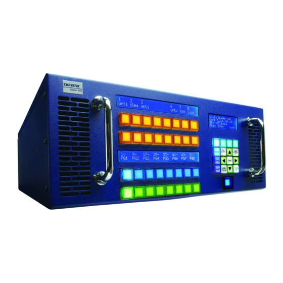
Page 142: X20 Front Panel
2. Composite / S-Video (Shares BNC with composite analog sync signal) 3. SDI / HD-SDI / 3G-SDI (Single dedicated BNC) Even Input Connectors (2, 4, 6, etc.) 1. DVI-I (Analog and Digital on single connector) 2. Stereo Sync input (3-Pin DIN) Spyder X20 User Manual 020-000916-01 Rev. 1 (04-2016) -
Page 143: Outputs
As the front panel functionality is dependent on the version of firmware running on the unit, actual front panel operation is discussed in detail in the software / operator’s manual for the X20. Spyder X20 User Manual 020-000916-01 Rev. 1 (04-2016) -
Page 144: Physical Specifications
Physical Specifications Dimensions (W x H x D) Spyder X20 4 RU: 17.3 x 7 x 21.9 inches (43.9 x 17.78 x 55.6 centimeters) Spyder 3 RU: 17.3 x 5.3 x 22.1 inches (43.9 x 13.3 x 56.1 centimeters) Spyder 2 RU: 17.3 x 3.5 x 22.1 inches (43.9 x 8.9 x 56.1 centimeters) -
Page 145: Rack Mount Instructions
Physical Specifications Rack mount Instructions Figure 52 : Rack Mounting Spyder X20 User Manual 020-000916-01 Rev. 1 (04-2016) -
Page 146: Spyder Expansion
Example: Two outputs at 1400 x 1050 each and one at 1920 x 1080 with a 640 x 480 operator’s monitor and a frame rate of NTSC use 5,788,800 pixels of the 6.6 million available. 5,788,800 pixels = 1080 x 1400 + 1400 + 1920 + 640 Spyder X20 User Manual 020-000916-01 Rev. 1 (04-2016) -
Page 147: Signal Flow
Although each individual Spyder Server is capable of supporting an entire VI, such as a standalone 344 model, I/O capacity is limited to the amount of input and output cards that can be mounted in a Spyder X20 User Manual 020-000916-01 Rev. 1 (04-2016) -
Page 148: Serial Expansion Group Example
Hardware available: 1. Spyder 344 (A) with expansion IP: 172.16.17.20 2. Spyder 344 (B) with expansion IP: 172.16.17.40 3. Spyder 240 with expansion IP: 172.16.17.60 One ISIS analog 16 x 16 matrix switch Spyder X20 User Manual 020-000916-01 Rev. 1 (04-2016) - Page 149 From the drop down menus select the matching IP address to frame in the order of the system starting from the master frame which is the 240. If doing a system configuration off-line choose ‘virtual’ instead of an IP address. After the frames are selected choose NTSC for frame rate. Click Next. Spyder X20 User Manual 020-000916-01 Rev. 1 (04-2016)
- Page 150 Screen Configurations window and fill in the appropriate output information as follows: Horizontal Outputs: 3 Vertical Outputs: 1 Horizontal Overlap: 512 Format: 2048 x 1080 @ 59.94 Connection: DVI if required Rotation: none Layers: 12 Spyder X20 User Manual 020-000916-01 Rev. 1 (04-2016)
-
Page 151: Discreet Expansion
Discreet expansion allows the use of multiple VI’s using multiple Frame Groups however the layers/inputs associated with those Frame Groups that make up an individual VI cannot extend to outputs of other Frame Spyder X20 User Manual 020-000916-01 Rev. 1 (04-2016) -
Page 152: Discreet Expansion Example
1. Spyder 344 (A) with expansion IP: 172.16.17.20 2. Spyder 344 (B) with expansion IP: 172.16.17.40 3. Spyder 240 with expansion IP: 172.16.17.60 4. One ISIS analog 16 x 16 matrix switch Spyder X20 User Manual 020-000916-01 Rev. 1 (04-2016) - Page 153 From the drop down menus select the matching IP address to frame in the order of the system starting from the master frame which is the 240. If doing a system configuration off-line choose ‘virtual’ instead of an IP address. After the frames are selected choose NTSC for frame rate. Click Next. Spyder X20 User Manual 020-000916-01 Rev. 1 (04-2016)
- Page 154 Configurations window and fill in the appropriate output information as follows: Horizontal Outputs: 3 Vertical Outputs: 1 Horizontal Overlap: 512 Format: 2048 x 1080 @ 59.94 Connection: DVI if required Rotation: none Layers: 8 Spyder X20 User Manual 020-000916-01 Rev. 1 (04-2016)
- Page 155 Select next and apply the configuration to either the hardware (online) or to local PC (offline). This completes the configuration and the patch and simulator portion of the GUI will look like the example below. Spyder X20 User Manual 020-000916-01 Rev. 1 (04-2016)
-
Page 156: Seamless Parallel Expansion
Restricted Layers Restricted layers can be placed anywhere in their home Pixel Renewal Group. However, Restricted Layers cannot be shown outside their own Renewal Group, or on the overlap between renewal groups. Spyder X20 User Manual 020-000916-01 Rev. 1 (04-2016) -
Page 157: Combining Restricted And Unrestricted Layers
Connect 240 (A) to 344 (A) to 240 (B) to 344 (B) to 240 (C) to 344 (C). The frame 240 (A) will be the master frame and remainder frames slaves. Make sure all frames are on the same network and connected. Connect the first Spyder X20 User Manual 020-000916-01 Rev. 1 (04-2016) - Page 158 ISIS serial cable to the Master Frame 240 (A) serial port. Open up the advanced software on the client PC and select File/New. The Spyder Configuration Manager will open and select Start with new empty configuration. Spyder X20 User Manual 020-000916-01 Rev. 1 (04-2016)
- Page 159 ‘none’. Continue with selecting ‘clear all’ and add the ISIS matrix switch. Select next and apply the configuration to either the hardware (online) or to local PC (offline). Spyder X20 User Manual 020-000916-01 Rev. 1 (04-2016)
- Page 160 Spyder Expansion This completes the configuration and the patch and simulator portions of the GUI will look like the example below. Spyder X20 User Manual 020-000916-01 Rev. 1 (04-2016)
-
Page 161: Configuring The Frame Groups And Their Aor
To define each frame group and its AOR refer to the below AOR diagram for this example to understand the next set of values that you will need to manually fill in the fields of the Frame Group hardware properties tab. AOR Diagram Spyder X20 User Manual 020-000916-01 Rev. 1 (04-2016) -
Page 162: Unrestricted Layers
Frame Group to be its slave. The three layers in the Selecting the slave master element layers Note in the above example each layer has a red indicator confirming their status as belonging to a Master Element. Spyder X20 User Manual 020-000916-01 Rev. 1 (04-2016) - Page 163 When using Master Elements the matrix switch will automatically switch the same source in the slave layers. Spyder X20 User Manual 020-000916-01 Rev. 1 (04-2016)
-
Page 164: Spyder X20 Hdcp Functionality (Option)
Spyder X20 HDCP Functionality (Option) Spyder X20 HDCP Functionality (Option) High-bandwidth Digital Content Protection (HDCP) is a form of digital copy protection developed by Intel to prevent copying of digital audio and video content as it travels across a digital interface. The system is meant to stop HDCP-encrypted content from being played on devices that do not support HDCP or which have been modified to copy HDCP content. - Page 165 X20 has two working modes with respect to HDCP. These modes take effect on a system-level and there is no combination involving both these modes at the same time with respect to the functions performed. Figure 2. illustrates a general connection topology of Spyder X20. 1. HDCP mode – HDCP-enabled devices can connect and transmit HDCP content to X20.
- Page 166 Router Router Figure 54: Connection Topology of Spyder X20 The mode selection is done in Frame Configuration option in the Vista Advanced Software and requires a server restart to take effect. In HDCP mode, all the interfaces except the HDCP-protected interfaces will be switched off.
- Page 167 Spyder X20 HDCP Functionality (Option) When an HDCP-enabled transmitter is connected to the input, the transmitter may encrypt the contents using HDCP before sending through the DVI/HDMI interface. HDCP Authentication can be divided into three stages. During the first stage, the transmitter and receiver exchanges the KSVs and calculates a secret private key by calculation done on Device Keys and a pseudo-random number generated by the transmitter's Cipher.
-
Page 168: Configuring Hdcp Mode
Spyder X20 HDCP Functionality (Option) In HDCP mode, all downstream traffic from X20 will be encrypted using HDCP Cipher irrespective of the nature of incoming video through upstream connections. The upstream devices may choose to encrypt or not to encrypt the contents based on the type of video content, but as soon as a device is connected downstream to X20, X20 starts the authentication process and only HDCP enabled displays or devices will function. -
Page 169: Displaying Hdcp Status In The Ui
Spyder X20 HDCP Functionality (Option) Displaying HDCP Status in the UI Output Status Each of the X20 outputs completes a handshake with a downstream device before video will begin outputting. The result of the handshake process will be displayed in the system patch utility, and will be represented as an icon on each of the outputs. - Page 170 Spyder X20 HDCP Functionality (Option) Spyder X20 User Manual 020-000916-01 Rev. 1 (04-2016)
-
Page 171: Updating A Fielded X20 To Support Hdcp
Adding HDCP support to the X20 involves a combination of hardware, firmware, and licensing modification. An HDCP license can technically be purchased for any fielded system, however a factory return may be required to apply the required updates. Please consult the factory for details. Spyder X20 User Manual 020-000916-01 Rev. 1 (04-2016)
Need help?
Do you have a question about the Spyder X20 and is the answer not in the manual?
Questions and answers