Table of Contents
Advertisement
Quick Links
Emergency Locator Transmitter
Description, Operation, Installation and Maintenance Manual
This manual includes data for the following equipment:
Component
Emergency Locator Transmitter
2-Wire Remote Switch
Mounting Tray
Installation Kit
Antenna w/Coax (black)
Cable, Coaxial, BNC to BNC, 6 ft
ELT 345 Kit
Battery Pack, LiMnO
External Buzzer
ARTEX ELT 345
Y1-03-0282 Rev. E
Labeled Part No.
2
25-62-35
Purchase Part No.
A3-06-2880
A3-06-2759
A3-06-2882
455-7423
A3-06-2892-1
611-6013-04
8102
A3-06-2883
452-6505
ARTEX PRODUCTS / ACR ELECTRONICS, INC.
5757 Ravenswood Rd, Ft. Lauderdale, FL 33312
8100
8304
8323
455-7423
8324 in kit
611-6013-04
8102
8322
452-6505
Page 1 of 58
JUN 15/16
Y1-03-0282 Rev. E
Initial Issue August 6, 2015
Cage Code: 18560
Advertisement
Table of Contents

Summary of Contents for ARTEX ELT 345
- Page 1 Battery Pack, LiMnO A3-06-2883 8322 External Buzzer 452-6505 452-6505 Page 1 of 58 JUN 15/16 25-62-35 Y1-03-0282 Rev. E Initial Issue August 6, 2015 ARTEX PRODUCTS / ACR ELECTRONICS, INC. 5757 Ravenswood Rd, Ft. Lauderdale, FL 33312 Cage Code: 18560...
- Page 2 ARTEX PRODUCTS / ACR ELECTRONICS, INC DESCRIPTION, OPERATION, INSTALLATION AND MAINTENANCE MANUAL ELT 345 (P/N: A3-06-2880) PROPRIETARY INFORMATION This document contains proprietary information and such information may not be disclosed to others for any purpose, nor used for manufacturing purposes without written permission from ACR Electronics.
-
Page 3: Record Of Revisions
ARTEX PRODUCTS / ACR ELECTRONICS, INC DESCRIPTION, OPERATION, INSTALLATION AND MAINTENANCE MANUAL ELT 345 (P/N: A3-06-2880) RECORD OF REVISIONS REVISION CHANGE DATE REVISION CHANGE DATE W/I 05-EN-05 Aug 06/15 ECO 16144 Sept 15/15 ECO 16240 Jan 19/16 ECO 16376 May 9/16... -
Page 4: Service Bulletin List
ARTEX PRODUCTS / ACR ELECTRONICS, INC DESCRIPTION, OPERATION, INSTALLATION AND MAINTENANCE MANUAL ELT 345 (P/N: A3-06-2880) SERVICE BULLETIN LIST SERVICE ISSUE MANUAL MANUAL SUBJECT BULLETIN NO DATE REV NO REV DATE 25-62-35 Page 4 of 58... -
Page 5: List Of Effective Pages
ARTEX PRODUCTS / ACR ELECTRONICS, INC DESCRIPTION, OPERATION, INSTALLATION AND MAINTENANCE MANUAL ELT 345 (P/N: A3-06-2880) LIST OF EFFECTIVE PAGES SUBJECT PAGE DATE SUBJECT PAGE DATE Title Page Test and Fault Isolation (cont.) Jun 15/16 Sept 15/15 Notices Sept 15/15... -
Page 6: Table Of Contents
ARTEX PRODUCTS / ACR ELECTRONICS, INC DESCRIPTION, OPERATION, INSTALLATION AND MAINTENANCE MANUAL ELT 345 (P/N: A3-06-2880) TABLE OF CONTENTS RECORD OF REVISIONS ........................... 3 SERVICE BULLETIN LIST ........................... 4 LIST OF EFFECTIVE PAGES ........................5 TABLE OF CONTENTS ..........................6 LIST OF FIGURES ............................. - Page 7 ARTEX PRODUCTS / ACR ELECTRONICS, INC DESCRIPTION, OPERATION, INSTALLATION AND MAINTENANCE MANUAL ELT 345 (P/N: A3-06-2880) Other Countries ........................24 Inspection and Test Procedures ....................25 Checklist ..........................25 Preparation ......................... 25 Coax Cable and Wiring Connections Inspection – Item 1 ............25 Mounting Tray and Hardware Inspection –...
- Page 8 ARTEX PRODUCTS / ACR ELECTRONICS, INC DESCRIPTION, OPERATION, INSTALLATION AND MAINTENANCE MANUAL ELT 345 (P/N: A3-06-2880) Buzzer ............................44 Location ..........................44 Installation .......................... 44 Wiring ............................45 General Considerations and Recommendations ..............45 Remote Switch Harness Fabrication ..................46 ELT D-Sub Plug Installation ....................
-
Page 9: List Of Figures
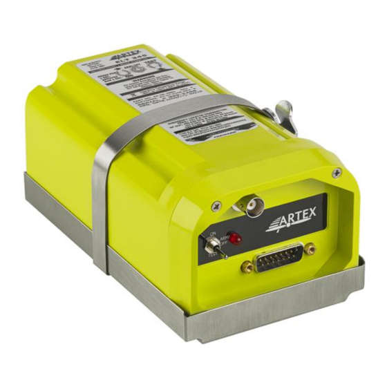
DESCRIPTION, OPERATION, INSTALLATION AND MAINTENANCE MANUAL ELT 345 (P/N: A3-06-2880) LIST OF FIGURES Figure 1 ARTEX ELT 345 Beacon and Mounting Tray ................18 Figure 2 Remote Switch Front View ....................18 Figure 3 Buzzer ..........................19 Figure 4 Battery Pack Assembly ......................19 Figure 5 Antennas ........................... -
Page 10: Introduction
1) This manual describes the operation, installation and maintenance of the ARTEX ELT 345 emergency locator transmitter (ELT). The information is provided to ensure initial and continued airworthiness. Information presented in this manual is accurate at the time of printing, but is subject to change. Refer to the ARTEX web site at www.acrartex.com... -
Page 11: Model Description
2) If the battery is installed by a third party, it must be ascertained whether it is an ARTEX Authorized Service center. To find an authorized service center, go to http://www.acrartex.com/where-to-buy/find-a-battery-service-provider/... -
Page 12: Rtca Do-160G Compliance
ARTEX PRODUCTS / ACR ELECTRONICS, INC DESCRIPTION, OPERATION, INSTALLATION AND MAINTENANCE MANUAL ELT 345 (P/N: A3-06-2880) SUBTASK 25-62-35-990-003 C. RTCA DO-160G Compliance 1) DO-160G Environmental Categories: [C1X]BC[DO-204a][S(C)]XRXXXSZZAZ[ZCX][DO-204a]M[XXXXXX][XXXX]XXX 2) The DO-160G environmental categories breakdown is detailed in Table 1. SECTION DESCRIPTION... -
Page 13: Frequency Allocation
1) The product identification label on each ELT specifies the transmission frequencies of the individual ELT. The ARTEX ELT 345 transmits a frequency of 406.040 MHz. Allocation of frequencies, based on beacon population per specified frequency band, is controlled by COSPAS-SARSAT. -
Page 14: List Of Acronyms, Abbreviations And Definitions
ARTEX PRODUCTS / ACR ELECTRONICS, INC DESCRIPTION, OPERATION, INSTALLATION AND MAINTENANCE MANUAL ELT 345 (P/N: A3-06-2880) TASK 25-62-35-990-805 5. List of Acronyms, Abbreviations and Definitions SUBTASK 25-62-35-990-001 Term Definition Advisory Circular – Federal Aviation Administration (USA) bulletin with special information. - Page 15 ARTEX PRODUCTS / ACR ELECTRONICS, INC DESCRIPTION, OPERATION, INSTALLATION AND MAINTENANCE MANUAL ELT 345 (P/N: A3-06-2880) FSDO Flight Standards District Office – FAA district offices responsible for aircraft certification, operation, maintenance and modification issues, approvals and enforcement. G-SWITCH Velocity switch that detects sudden deceleration and is used to automatically activate an ELT;...
-
Page 16: References
(ELT)” SUBTASK 25-62-35-990-002 B. Other Documents 1) The ARTEX model beacon programmer or beacon test set operating manuals are available from ACR Electronics upon request: a) Document number 570-1000, “453-1000 ELT Test Set Operation” b) Document number 570-2000, “453-2000 Handheld Programmer Operations Manual”... -
Page 17: Description And Operation
ARTEX PRODUCTS / ACR ELECTRONICS, INC DESCRIPTION, OPERATION, INSTALLATION AND MAINTENANCE MANUAL ELT 345 (P/N: A3-06-2880) DESCRIPTION AND OPERATION TASK 25-62-35-870-801 1. Description SUBTASK 25-62-35-870-001 A. Functional Overview 1) The ELT automatically activates during a crash and transmits a continuous standard sweep tone on the 121.5 MHz frequency. -
Page 18: System Components
SUBTASK 25-62-35-870-002 B. System Components 1) The ARTEX ELT 345 housing assembly is made of high impact, fire resistant, polycarbonate-polyester plastic. The tray is fabricated from aluminum, with a stainless steel holding strap. See Figure 1. Figure 1 ARTEX ELT 345 Beacon and Mounting Tray 2) The cockpit-mounted remote switch assembly includes a status LED and control switch. -
Page 19: Figure 3 Buzzer
4) The battery pack for the ARTEX ELT 345 consists of two “D” size Lithium Manganese Dioxide cells (see Figure 4). Figure 4 Battery Pack Assembly 5) There is only one type of antenna that is approved for use with the ARTEX ELT 345 (see Figure 5). This antenna is ARTEX part # A3-06-2892-1 Figure 5 Antennas... -
Page 20: Operation
SUBTASK 25-62-35-870-001 A. Overview 1) A primary feature of the ARTEX ELT 345 is its simplicity of operation. 2) A connection jumper (“G-switch loop”) between pins 5 and 12 on the D-sub receptacle enables the G-switch circuitry, allowing activation when the acceleration threshold is exceeded. The jumper is located in the mating D-sub receptacle of the cockpit remote switch wire harness. -
Page 21: Elt Reset
1) A monthly functional check is recommended to verify operational status of the ELT. Perform in accordance with SUBTASK 25-62-35-750-009 on page 30. TASK 25-62-35-870-803 3. Specifications SUBTASK 25-62-35-870-001 A. Environmental and Physical 1) Table 2 lists the environmental and physical specifications of the ELT 345. CRITERIA PARAMETER CHARACTERISTIC Storage -55°C to +85°C... -
Page 22: Electrical
ARTEX PRODUCTS / ACR ELECTRONICS, INC DESCRIPTION, OPERATION, INSTALLATION AND MAINTENANCE MANUAL ELT 345 (P/N: A3-06-2880) SUBTASK 25-62-35-870-002 B. Electrical 1) Table 3 lists the electrical specifications of the ELT 345. CRITERIA PARAMETER CHARACTERISTIC 406.040 MHz ± 1 kHz Operating Frequencies 121.5 MHz... -
Page 23: Antenna
23.4 in (594 mm) NOTE: The ARTEX recommended coaxial cable Part No. 611-6013-04 (6 ft) complies with the minimum and maximum cable insertion losses quoted above. If the installer has a need for a longer cable run, the use of a low-loss cable that meets the equivalent cable loss in dB must be utilized. -
Page 24: Test And Fault Isolation
Antenna, including trailing antenna, for poor condition, insecure mounting, and improper operation NOTE: ARTEX recommends using www.406Test.com to ensure the ELT 345 is testing through-the-satellite during annual inspections and initial installations. SUBTASK 25-62-35-990-002 B. Canada 1) CAR Part VI, Standard 625, Appendix C, requires the ELT to be inspected at intervals not exceeding 12 months. -
Page 25: Inspection And Test Procedures
ARTEX PRODUCTS / ACR ELECTRONICS, INC DESCRIPTION, OPERATION, INSTALLATION AND MAINTENANCE MANUAL ELT 345 (P/N: A3-06-2880) TASK 25-62-35-750-802 2. Inspection and Test Procedures SUBTASK 25-62-35-990-001 A. Checklist 1) Table 5 provides a list of the ELT inspection and testing requirements, a copy of which may be used as a checklist to verify inspection and test completion. -
Page 26: Mounting Tray And Hardware Inspection - Item 2
ARTEX PRODUCTS / ACR ELECTRONICS, INC DESCRIPTION, OPERATION, INSTALLATION AND MAINTENANCE MANUAL ELT 345 (P/N: A3-06-2880) SUBTASK 25-62-35-220-002 D. Mounting Tray and Hardware Inspection – Item 2 1) Inspect mounting tray for cleanliness, cracks, and other damage. 2) Check mounting tray hardware for corrosion and security. -
Page 27: Performance Test Setup
If the operation time exceeds one hour, an error indicator will be displayed when a self-test is performed (see SUBTASK 25-62-35-810-001 on page 31). This does not affect the normal operation of the ELT 345, but provides an indication to the user that the battery must be replaced, in order to comply with the FAA requirements. -
Page 28: 121.5 Mhz Power Output Measurement - Item 5C
ARTEX PRODUCTS / ACR ELECTRONICS, INC DESCRIPTION, OPERATION, INSTALLATION AND MAINTENANCE MANUAL ELT 345 (P/N: A3-06-2880) SUBTASK 25-62-35-750-004 I. 121.5 MHz Power Output Measurement – Item 5c 1) Connect the measuring device as specified in Figure 6 Performance Test Setup on page 27. -
Page 29: Digital Message Verification - Item 5G
SUBTASK 25-62-35-750-008 M. Digital Message Verification – Item 5g 1) Use a beacon reader, such as ARTEX P/N 453-1000, 453-2000, 8700, or 8701 to test the transmitted digital message. 2) Connect the beacon tester to the ELT, per the instructions of the reader. -
Page 30: Elt Reset Check - Item 5H
ARTEX PRODUCTS / ACR ELECTRONICS, INC DESCRIPTION, OPERATION, INSTALLATION AND MAINTENANCE MANUAL ELT 345 (P/N: A3-06-2880) Figure 8 Short & Long 406 MHz Message Examples SUBTASK 25-62-35-750-009 N. ELT Reset Check – Item 5h 1) Place the ELT control switch in the ON position. -
Page 31: Antenna Test - Item 7
ARTEX PRODUCTS / ACR ELECTRONICS, INC DESCRIPTION, OPERATION, INSTALLATION AND MAINTENANCE MANUAL ELT 345 (P/N: A3-06-2880) SUBTASK 25-62-35-750-011 P. Antenna Test – Item 7 CAUTION: DO NOT ALLOW THE DURATION OF THIS TEST TO EXCEED 5 SECONDS. 1) Tune a low quality AM receiver (i.e., radio) to 121.5 MHz. - Page 32 One pulse two seconds long of the status LED, remote light, and buzzer. This pulse is suppressed if problems are found during self-test. Code not used in the ELT 345 Code not used in the ELT 345 Low output power...
-
Page 33: Troubleshooting
ARTEX PRODUCTS / ACR ELECTRONICS, INC DESCRIPTION, OPERATION, INSTALLATION AND MAINTENANCE MANUAL ELT 345 (P/N: A3-06-2880) SUBTASK 25-62-35-810-002 B. Troubleshooting SYMPTOM PROBABLE CAUSE POSSIBLE SOLUTION Improper wiring Verify wiring Remote switch LED always on Short circuit Verify integrity of all crimp and... -
Page 34: Removal
ARTEX PRODUCTS / ACR ELECTRONICS, INC DESCRIPTION, OPERATION, INSTALLATION AND MAINTENANCE MANUAL ELT 345 (P/N: A3-06-2880) REMOVAL TASK 25-62-35-010-801 1. ELT SUBTASK 25-62-35-010-001 A. ELT Removal 1) See Figure 9 ELT Removal Sequence. Figure 9 ELT Removal Sequence 2) Disconnect the antenna coax cable. -
Page 35: Battery
ARTEX PRODUCTS / ACR ELECTRONICS, INC DESCRIPTION, OPERATION, INSTALLATION AND MAINTENANCE MANUAL ELT 345 (P/N: A3-06-2880) TASK 25-62-35-050-801 2. Battery SUBTASK 25-62-35-050-001 A. Battery Removal CAUTION: THE BATTERY PACK CONTAINS ELECTROSTATIC DISCHARGE (ESD) SENSITIVE COMPONENTS AND IT MUST BE HANDLED WITH CARE. IF POSSIBLE, WEAR A GROUNDED WRIST STRAP WHEN HANDLING THE BATTERY PACK DURING INSTALLATION ACTIVITIES. -
Page 36: Material Or Equipment Return
ARTEX PRODUCTS / ACR ELECTRONICS, INC DESCRIPTION, OPERATION, INSTALLATION AND MAINTENANCE MANUAL ELT 345 (P/N: A3-06-2880) TASK 25-62-35-500-801 3. Material or Equipment Return SUBTASK 25-62-35-510-001 A. Shipment Information 1) If any material or equipment is to be returned to the factory, under warranty or otherwise, ACR Electronics must... -
Page 37: Installation
ARTEX PRODUCTS / ACR ELECTRONICS, INC DESCRIPTION, OPERATION, INSTALLATION AND MAINTENANCE MANUAL ELT 345 (P/N: A3-06-2880) INSTALLATION TASK 25-62-35-410-001 1. Regulatory Requirements and Guidelines SUBTASK 25-62-35-990-001 A. For US Registered aircraft: WARNING: FAILURE TO REGISTER THIS ELT WITH NOAA BEFORE INSTALLATION COULD RESULT IN A MONETARY FORFEITURE BEING ISSUED TO THE OWNER. -
Page 38: Canada
ARTEX PRODUCTS / ACR ELECTRONICS, INC DESCRIPTION, OPERATION, INSTALLATION AND MAINTENANCE MANUAL ELT 345 (P/N: A3-06-2880) SUBTASK 25-62-35-990-004 D. Canada 1) All installations must be performed in accordance with Canadian Aviation Regulations (CAR) Part V, Chapter 551, § 551.104. SUBTASK 25-62-35-990-005 E. -
Page 39: Mounting Tray
Statistics show that the tail section of an airplane is likely to be less damaged during a crash; therefore, providing a good mounting environment for the ELT. Figure 11 ARTEX ELT 345 Outline & Dimensions 25-62-35 Page 39 of 58... -
Page 40: Figure 12 Elt 345 Metal Strap Minimum Clearance Dimensions
Figure 12 ELT 345 Metal Strap Minimum Clearance Dimensions 1) Select a suitable location for the ELT mounting tray (see Figure 11 ARTEX ELT 345 Outline & Dimensions on page 39 and Figure 12 ELT 345 Metal Strap Minimum Clearance Dimensions above). -
Page 41: Installation
ARTEX PRODUCTS / ACR ELECTRONICS, INC DESCRIPTION, OPERATION, INSTALLATION AND MAINTENANCE MANUAL ELT 345 (P/N: A3-06-2880) SUBTASK 25-62-35-450-002 B. Installation 1) See Figure 13 Typical Mounting Tray Installation. 2) Install the necessary mounting structure as appropriate. 3) Align the mounting tray (A3-06-2882) on the mounting structure, such that the arrow on the tray is within 10°... -
Page 42: Antenna
SUBTASK 25-62-35-990-001 A. General 1) Use only antennas approved for use with the ARTEX ELT 345. The ELT will not work properly without being connected to an antenna for which it was designed. 2) Verify the antenna selected matches the requirements of the specific installation. Considerations include aircraft maximum rated speed, location restrictions, and any other considerations specific to the installation. -
Page 43: Remote Switch
A. Location NOTE: The ELT 345 must be installed using a 2-wire remote switch, ARTEX P/N A3-06-2757. Note that the 2-wire remote switch does not require a connection to the aircraft power to operate. 1) Select a suitable switch location in the cockpit. The switch needs to be visible and accessible, where the pilot can easily reach the switch and notice the indicator LED. -
Page 44: Buzzer
3) Drill the screw holes with a #28 or 3.6 mm drill. 4) Install the switch assembly using the hardware provided in the remote switch installation kit . 5) Apply the “For Aviation Emergency Use Only/Unauthorized Use Prohibited” placard (ARTEX P/N 591-0428, provided in the installation kit). -
Page 45: Wiring
ARTEX PRODUCTS / ACR ELECTRONICS, INC DESCRIPTION, OPERATION, INSTALLATION AND MAINTENANCE MANUAL ELT 345 (P/N: A3-06-2880) TASK 25-62-35-450-805 6. Wiring SUBTASK 25-62-35-990-001 A. General Considerations and Recommendations CAUTION: IF GROUND OR OTHER CONNECTIONS ARE BROKEN OR OTHERWISE DAMAGED, THE ELT IS STILL CAPABLE OF AUTOMATIC ACTIVATION;... -
Page 46: Remote Switch Harness Fabrication
ARTEX PRODUCTS / ACR ELECTRONICS, INC DESCRIPTION, OPERATION, INSTALLATION AND MAINTENANCE MANUAL ELT 345 (P/N: A3-06-2880) Figure 18 Typical 2-Wire Installation for Shielded Harness SUBTASK 25-62-35-450-001 B. Remote Switch Harness Fabrication 1) See Figure 19 Remote Switch Harness Arrangement. 2) Allow enough slack to provide a drip loop at the ELT end and a service loop at the cockpit remote switch end. - Page 47 ARTEX PRODUCTS / ACR ELECTRONICS, INC DESCRIPTION, OPERATION, INSTALLATION AND MAINTENANCE MANUAL ELT 345 (P/N: A3-06-2880) Figure 19 Remote Switch Harness Arrangement 25-62-35 Page 47 of 58...
-
Page 48: Elt D-Sub Plug Installation
ARTEX PRODUCTS / ACR ELECTRONICS, INC DESCRIPTION, OPERATION, INSTALLATION AND MAINTENANCE MANUAL ELT 345 (P/N: A3-06-2880) SUBTASK 25-62-35-450-002 C. ELT D-Sub Plug Installation 1) See Figure 20 Harness Plug Assembly. 2) Select a rubber grommet, supplied as part of the D-Sub housing kit (150-1127), that fits snugly around the harness wiring. -
Page 49: Cockpit Remote Switch 9-Pin Plug Installation
1) ELTs that are serialized with LONG Cospas-Sarsat protocol will receive external navigation data if available. 2) ELTs programmed with SHORT Cospas-Sarsat protocol will not accept navigation data. 3) When the ELT 345 is programmed with 4800 baud it will only accept NMEA, and when programmed with 9600 baud it will only accept Aviation Protocol. -
Page 50: Harness Elt D-Sub Plug Sealing
ARTEX PRODUCTS / ACR ELECTRONICS, INC DESCRIPTION, OPERATION, INSTALLATION AND MAINTENANCE MANUAL ELT 345 (P/N: A3-06-2880) 1) See Figure 21 ELT Installation Sequence. Figure 21 ELT Installation Sequence 2) Insert the ELT into the mounting tray at an angle, engaging the locking ears at the tail end first. Press the ELT down until it is fully seated in the mounting tray. -
Page 51: Installation Documentation
ARTEX PRODUCTS / ACR ELECTRONICS, INC DESCRIPTION, OPERATION, INSTALLATION AND MAINTENANCE MANUAL ELT 345 (P/N: A3-06-2880) c) Inject sealant into the back side of the plug, so that sealant surrounds all exposed electrical connections and the back of the plug. - Page 52 ARTEX PRODUCTS / ACR ELECTRONICS, INC DESCRIPTION, OPERATION, INSTALLATION AND MAINTENANCE MANUAL ELT 345 (P/N: A3-06-2880) 8) Replace the four screws. Apply a 5 in-lb. torque on the screws. Tighten as below before torque is applied in the same way.
-
Page 53: Illustrated Parts List
SUBTASK 25-62-35-990-001 A. Ordering Information 1) Parts may be ordered from ACR Electronics, or any authorized dealer. CONTACT INFORMATION: Sales, ACR Electronics, Inc. / ARTEX Products 5757 Ravenswood Rd Fort Lauderdale, FL 33312-6603 USA Phone: (954) 981-3333 Fax: (954) 983-5087... -
Page 54: Figure 22 Elt 345 Main Assembly And Installation
ARTEX PRODUCTS / ACR ELECTRONICS, INC DESCRIPTION, OPERATION, INSTALLATION AND MAINTENANCE MANUAL ELT 345 (P/N: A3-06-2880) Figure 23 ELT 345 Main Assembly and Installation ITEM PART # DESCRIPTION A3-06-2880 ARTEX ELT 345 Main Assembly A3-06-2883 Lithium Battery Pack 201-0402 Screw, 6-32 x 7/8, PHL, Truss, SS... -
Page 55: Figure 23 Harness Components
ARTEX PRODUCTS / ACR ELECTRONICS, INC DESCRIPTION, OPERATION, INSTALLATION AND MAINTENANCE MANUAL ELT 345 (P/N: A3-06-2880) Figure 24 Harness Components ITEM PART # DESCRIPTION A3-06-2759 Switch, cockpit remote 201-0408 Screw, PHL, 4-40 x ¼”, SS 247-0400 Washer, internal lock, SS, #4 241-0440 Nut, 4-40 x ¼”, hex, SS... -
Page 56: Figure 24 Antennas
ARTEX PRODUCTS / ACR ELECTRONICS, INC DESCRIPTION, OPERATION, INSTALLATION AND MAINTENANCE MANUAL ELT 345 (P/N: A3-06-2880) Figure 25 Antennas ITEM PART # DESCRIPTION A3-06-2892-1 RAMI Whip Ant (black) w/6’ Coax Cable Table 10 Antennas 25-62-35 Page 56 of 58... -
Page 57: Appendix A - Elt Registration
ARTEX PRODUCTS / ACR ELECTRONICS, INC DESCRIPTION, OPERATION, INSTALLATION AND MAINTENANCE MANUAL ELT 345 (P/N: A3-06-2880) APPENDIX A – ELT REGISTRATION TASK 25-62-35-990-801 1. Background Information SUBTASK 25-62-35-990-001 A. Hex ID Code (15-Hex ID) 1) A Hexadecimal Identification (Hex ID) is a series of digits consisting of letters A-F and numbers 0-9 that identifies an individual beacon. -
Page 58: Registration Information Resources
2) Specific registration web sites and information may be found at: a) The ARTEX products web site at www.acrartex.com, which has links to on-line registration sites and also a link to registration forms and instructions for a number of countries.
Need help?
Do you have a question about the ELT 345 and is the answer not in the manual?
Questions and answers