Table of Contents
Advertisement
Quick Links
Advertisement
Table of Contents

Summary of Contents for Scireq flexivent
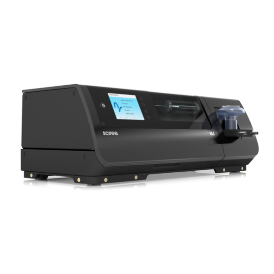
- Page 1 USER MANUAL INTEGRATED PLATFORM. PRECLINICAL. PULMONARY RESEARCH.
- Page 3 WELCOME TO THE FLEXIVENT FX Congratulations, and thank you for selecting the flexiVent ! The flexiVent FX combines the most accurate, detailed and reproducible measurements of respiratory mechanics with flexible and efficient experimentation management. flexiVent FX operates with flexiWare software in a system designed for...
- Page 5 The information contained in this manual is believed to be accurate at the time of print. However, SCIREQ Scientific Respiratory Equipment Inc. does not offer any warranties, express or implied, for the content of the manual and the use of all related products. The license and operating conditions apply.
-
Page 6: Safety Considerations
When carrying or moving the flexiVent , always ensure that the device is kept horizontal and supported by two hands underneath the unit. The power cord used should comply with local standards. Use only the power supply provided by SCIREQ with the flexiVent system. - Page 7 Only gases may be introduced through the air intake (e.g. room air, non-flammable mixed gas, inhaled anesthesia). Introduction of other substances through the air/gas intake, e.g. particulates or aerosol, may damage the module’s piston. Always unscrew the piston rod before attempting to remove the module from the base unit. Handle the module carefully.
- Page 8 When you are using and handling the flexiVent , always observe all of the cautionary notes included in this manual. SCIREQ is not liable for damage or injury resulting from misuse of this product. LIST OF SYMBOLS The following table describes the electrical and safety symbols that may be displayed on the flexiVent FX.
- Page 9 SYMBOL DESCRIPTION Auxiliary channels Synchronization port (in) Synchronization port (out) Power supply connection Intake/Inspiratory line Exhaust/Expiratory line Inappropriate for disposal in general waste Aluminum components; please recycle as appropriate Internal magnet...
-
Page 10: Table Of Contents
Introduction ..................................11 Intended Use ................................11 UnitWise Platform & flexiWare ........................12 flexiVent FX System Overview ........................16 Theory of Operation ............................17 Set up & Installation ..............................25 ... -
Page 11: Table Of Contents
Nebulizer ................................54 Calibration Accessories ..........................57 Hardware Extension for Negative Pressure Forced Expirations (NPFE) ......58 Multi-subject Extension (MSX) ......................60 Cleaning, Decontamination and Maintenance ..................... 61 Cylinder ..................................61 ... -
Page 13: Introduction
Table A-2. flexiVent If you intend to use the outside typical operating conditions explained in this user manual, please contact SCIREQ Technical Support for additional instructions and documentation. flexiVent is not intended for use with human subjects. - Page 14 FLEXIWARE UNITWISE PLATFORM & flexiVent UnitWise FX is built on the second generation platform, a fully digital, data acquisition and control architecture designed to be operated by flexiWare software. For additional details on flexiWare refer to the flexiWare user manual.
- Page 15 1.2.1 WORKSTATIONS UnitWise platform uses standard Ethernet connectivity as the backbone to connect the high-level components of a UnitWise data acquisition and experimentation environment. The UnitWise list of high-level components includes the individual instruments (see section 1.2.2), flexiWare experimentation and review workstations (both running ), and the database server on which data may be stored in a central location.
- Page 16 FIGURE 1-2: UNIVERSAL INTELLIGENT TRANSDUCER (UNIT) ARCHITECTURE 1.2.3 PORTS, UNITS & CHANNELS UnitWise instruments typically possess eight ports, each of which may be occupied by one Universal Intelligent Transducer (UNIT) without further adapters, amplifiers or pods, so that any UNIT can fit into and be recognized by any instrument port (see Figure 1-2). Every UNIT contains between one and four sensor elements or other input/output channels, each permitting the measurement or modification of a physical property.
- Page 17 1.2.4 INTEGRATED SYSTEMS UnitWise terminology, some SCIREQ products are referred to as “integrated systems” since they contain both an instrument and one or more UNITs in a common package. For example, a flexiVent UnitWise FX has all features of a...
-
Page 18: Flexivent Fx System Overview
, menus and commands are automatically configured in the software such that you have complete access to your instrument’s functionality. The instrument-specific configuration flexiWare is controlled by licensing, SDMs and template mechanisms. It does not require any additional steps or configuration settings during operation. All commands necessary for your application are available for your use, following setup and installation. -
Page 19: Theory Of Operation
SCIREQ products and third-party products. 1.4.1 RESPIRATORY MECHANICS Generally speaking, mechanics is the relationship of objects and the forces that act upon them. - Page 20 For detailed information about perturbation properties, refer to the user manual. TABLE 1-1: STANDARD FLEXIVENT PERTURBATIONS NAME DESCRIPTION SAMPLE Deep inflation of the subject's lungs to a pressure of 30 cmH20...
- Page 21 NAME DESCRIPTION SAMPLE Single frequency, sinusoidal forced oscillation waveform. The oscillation frequency is typically SnapShot matched to the subject's respiratory rate (e.g. "SnapShot- 150" for mice breathing at 150 br/min). Broadband (multi-frequency) forced oscillation waveforms, Primewave typically denoted by duration (e.g. "Prime-8"...
- Page 22 1.4.3 INDIRECT MEASUREMENT flexiVent uses the indirect measurement technique to assess respiratory mechanics. In animal subjects, especially those that do not generate large tidal flows, precise flow measurement can be quite difficult. Flow measurement difficulty is compounded by signal losses due to gas compression, so use of flow measurements to calculate mechanics is technically challenging.
- Page 23 1.4.4 SERVO-CONTROLLED PISTON The module of the flexiVent FX contains the piston/cylinder set. Movement of the piston is servo-controlled through a closed feedback-control loop as in Figure 1-2. The piston is driven by the linear actuator in the base unit and its position is measured by an optical sensor. The differential pressures in the cylinder and ventilator compartment are measured by transducers within the module.
- Page 24 (in which the Deep Inflation is used to ensure consistent inflation prior to image acquisition). 1.4.6 INTERCHANGEABLE MODULES flexiVent As mentioned in section 1.3, the FX piston/cylinder set and valves that create the ventilator compartment are mounted on the portion of the system called the module. There are five modules currently available.
- Page 25 For questions regarding integration with a particular accessory, contact SCIREQ Technical Support or refer to user instructions provided with your additional hardware. Please note that only accessories approved and recommended by SCIREQ Technical support should be flexiVent used in conjunction with the...
-
Page 27: Set Up & Installation
2 SET UP & INSTALLATION The installation sequence described in this section applies to the hardware portion of flexiVent UnitWise configuring a FX instrument for use in a system. Customized installation procedures may be required for some application-specific configurations. Please read the set up and installation instructions for all of your system components before proceeding. - Page 28 FX system: flexiVent FX base unit; flexiVent one or more FX modules; THE FLEXIVENT AT A GLANCE a power supply; (OPPOSITE PAGE) an Ethernet cable; one or more FX adapters; BASE UNIT EMBEDDED DISPLAY one or more Y-tubing kits;...
- Page 29 FIGURE 2-1: THE FLEXIVENT FX...
-
Page 30: Placing The System
PLACING THE SYSTEM flexiVent and all extensions require a dry, flat, stable workspace of 2’ x 2’ x 2’ (60 x 60 x 60 cm). Ensure that the system is stable on the workbench. If the surface is not quite level, use the adjustable foot located under the front corner below the module to help level it and prevent unwanted vibrations. - Page 31 A selection of configurations is provided in Table 2-1; for configurations including hardware extensions or custom applications, refer to documentation that accompanies the hardware or information supplied by SCIREQ Technical Support.
- Page 32 (e.g. for collection or evacuation). 2.4.4.1 ALTERNATE INTAKE SOURCE flexiVent Alternate air sources or inhaled anaesthesia may be used with the . It is extremely important that the intake is not pressurized. In order to install an alternate external air source, use one of two methods to ensure that no pressure is applied: Use a very compliant bag and fill it with the desired gas mixture or the anaesthesia gas.
- Page 33 pulls back, it will draw in some of the gas mixture and then deliver it to the subject. Since the bag is very compliant, it will not pressurize the system. Use a flow-past circuit, which involves putting a T-piece on the intake (refill) port as shown in Figure 2-3.
- Page 34 2.4.5 SUBJECTS flexiVent, Before attaching a subject to the proceed through the start-up sequence described in section 1. Failure to initiate the start-up sequence in advance of connecting the subject may result in loss of the subject.
- Page 35 FIGURE 2-4: FX ADAPTER SHOWN WITH NEBULIZER MOUNT AND WITHOUT NEBULIZER MOUNT; SUBJECTS ARE ATTACHED AT THE END OF THE Y-TUBING. FLEXIVENT OPENING THE PROTECTIVE COVER flexiVent cover is locked in order to ensure protection from moving parts. Unlocking the cover should only be necessary in order to replace the module or for maintenance purposes.
-
Page 36: Working With An Alternate Module
FIGURE 2-5: COVER LOCK MECHANISM Press gently to unlock the cover. While pressing gently lift the cover to open it. WORKING WITH AN ALTERNATE MODULE As mentioned in section 2.2, the instrument ships with a module attached. If you have ordered an instrument that contains multiple modules, they will ship in separate packages. - Page 37 2.6.1.1 FX MODULES 1, 2 AND 3 FIGURE 2-6: ASSEMBLY STEPS, FX MODULES 1, 2 AND 3 Align the O-ring and the piston/cylinder assembly with the module per Figure 2-6. Insert screws to hold the piston/cylinder in place This step requires a 7/64” hex/allen wrench. Screws should be secure, but do not over-tighten them, as this may cause damage.
- Page 38 Rotate the piston/cylinder clockwise until it is secure, but do not over-tighten as this may cause damage. 2.6.2 REMOVING A MODULE FROM THE FX BASE UNIT Power off the flexiVent and disconnect it from its power supply. Open the base unit protective cover.
- Page 39 Unscrew the piston rod from the motor arm per Figure 2-8. FIGURE 2-8: PISTON ROD UNSCREWED FROM THE MOTOR ARM (LEFT) Loosen the module securing screw. FIGURE 2-9: MODULE SECURING SCREW Lift module upwards. Be sure to unscrew the piston before attempting to remove the module. Handle the module carefully.
- Page 40 Power off the and disconnect it from the power supply. Open the base unit protective cover. Lower the module onto the base unit. The module snaps into place once it is positioned correctly Tighten the module securing screw (see Figure 2-9).
-
Page 41: Getting Started
FX, always observe all of the cautionary safety notes included in this manual. SCIREQ is not liable for damage or injury resulting from misuse of the product. The following section is designed as a quick guide to using the... - Page 42 FIGURE 3-1: FLEXIWARE WELCOME DIALOGUE Start an experimentation session by selecting the Experimentation Session button on the Welcome dialogue, as highlighted in Figure 3-1. Default Study Select in the Study Selection dialogue. The default study contains two subject groups, Control Experimental Should you prefer to use a study that is customized to your research, refer to the flexiWare...
- Page 43 -Specific Features section of the user manual. flexiVent Confirm the module that is attached to the Subject Management Click to define one or more subjects that will be used in the current experimentation session.
- Page 44 FIGURE 3-3: GROUP MEMBERSHIP SELECTION OF SUBJECT DETAILS Click to exit subject management. Drag and drop the subject onto the measurement site. FIGURE 3-4: ASSIGNING A SUBJECT TO THE MEASUREMENT SITE If you have selected a template that includes aerosol delivery (e.g. a default template with ‘AN’...
- Page 45 The nebulizer will generate aerosol for a few seconds. Once this is complete place it securely on the mount of the FX adapter. Proceed to channel calibration Calibrate the cylinder pressure channel. Most templates require a two point calibration in which the first point is 0 mmH O (open to atmosphere) and the second point is approximately 300 mmH O (applied using a manometer) to cover the range of...
- Page 46 U-shaped manometer, the amount of pressure applied is equal to double the change in height on one of the columns. If you used a SCIREQ manometer, the amount of pressure applied is equal to the level of fluid in the single column. Please refer to the instructions provided with the SCIREQ manometer for further details.
- Page 47 FIGURE 3-8: RESULTS OF CALIBRATING THE AIRWAY OPENING PRESSURE CHANNEL If your values are not within the expected range, please see the note above regarding proper use of a manometer. Should you have questions, contact SCIREQ Technical Support. Characterize your Aeroneb nebulizer to obtain its output rate as well as the delivery...
- Page 48 (0.001g) and Rainout characterization kit will be required. Refer to the Advanced flexiWare features section in the user manual for further information. Verify the results when they are displayed. The nebulizer output rate should be greater than the values listed below for each nebulizer type. Fine mist (ANP-1100): 0.1 ml/min Standard mist (ANP-1000):0.3 ml/min Additional channels may require calibration depending on the template selected.
- Page 49 . If the cannula is not completely blocked, the calibration may need to be repeated. Closed Calibration flexiVent While the cannula is blocked, the executes each perturbation that you selected. Do not unblock the cannula until all perturbations are complete.
- Page 50 If your values are not acceptable, confirm that all tubing connections are tight and re-perform the calibration making sure the cannula is tightly blocked during the closed calibration. If you continue to get values that are not within acceptable range, please contact SCIREQ Technical Support.
- Page 51 Connect a subject to the Y-tubing with the same cannula that was used during calibration. Execute perturbation(s) to generate datasets, either by double-clicking the perturbation name in the perturbation docker or by typing the hotkey for the perturbation. Refer to the flexiVent-Specific Features section of the flexiWare user manual for perturbation settings and outcomes.
-
Page 52: Accessories
Transducer identification and calibrations are stored within the UNIT to eliminate uncertainty during experimentation or data review. If you prefer to manually calibrate a UNIT transducer before each experimentation session, contact SCIREQ Technical Support and request a custom SDM. - Page 53 Use of the transducers requires arterial access to the subject in which measurements are taken. It also requires physiological saline and two three-way stopcocks, not supplied by SCIREQ. Selection of the appropriate transducer is based on the range of pressures to be measured. The...
- Page 54 4.1.5 AUXILIARY PRESSURE SCIREQ offers a wide array of pressure sensors that are optimized to offer the highest sensitivity for a given pressure range. Each sensor comprises a pressure sensing element that is further linearized by a microprocessor. Use of auxiliary pressure transducers may be necessary if you wish to record pressure in a location outside the module.
- Page 55 -10.0 – 10.0 kPa (-102 – 102 cmH transducer, 10.0 kPa nominal Digital precision differential pressure -30.0 – 30.0 kPa (-305.9 – 305.9 UT-DPD-300 transducer, 30.0 kPa nominal To confirm whether or not a transducer is appropriate for a certain application, please contact SCIREQ Technical Support.
-
Page 56: Nebulizer
NEBULIZER flexiVent The nebulizer available for tight integration with is the Aeroneb Lab nebulizer, which is manufactured by Aerogen (Galway, Ireland). The Aeroneb uses ultrasonic vibrating plate technology to generate consistently-sized droplets without heat, shear force or propelled air, making it ideal for biological substances. There are two stock models available, see section 4.2.1 for details. - Page 57 Once you initiate the software you must select a template that is configured to include the Aeroneb nebulizer; templates automatically included with the flexiWare software include ‘AN’ in their filename if they are configured for nebulizer use. Before you proceed through calibration steps, the nebulizer is primed (run continuously) per the settings in the template to create a seal through which air will not escape.
- Page 58 4.2.1 AERONEB SPECIFICATIONS STANDARD FINE MIST MIST ANP-1100 ANP-1000 Particle Size (VMD – Volume Median Diameter) 3.5 μm 5 μm Nominal Nebulization Output Rate > 0.1 mL/min > 0.2 mL/min Residual Volume < 0.2 mL < 0.2 mL Mass Median Aerodynamic Diameter (MMAD) ~ 1.8 μm 2.5-3.0 μm Geometric Standard Deviation (GSD)
-
Page 59: Calibration Accessories
4.3.1 PRESSURE MANOMETER The SCIREQ pressure manometer is a J-column pressure manometer with a range of 0-300 O. The fluid used with the manometer must have specific gravity = 0.87. The ruler on the front of the manometer may be adjusted by loosening the silver screws on the ruler and moving the ruler to the appropriate location. -
Page 60: Hardware Extension For Negative Pressure Forced Expirations (Npfe)
4.3.2 RAINOUT CHARACTERIZATION KIT The SCIREQ rain-out characterization kit includes a drying tube and connective tubing as well as an instruction card. The rainout characterization kit is required when characterizing the flexiWare nebulizer in the software. To ensure accuracy during the nebulizer characterization, it is important to replace the drying tube once it has turned pink. - Page 61 SCIREQ currently offers the negative pressure forced expiration extension for mice and rats only. Clients should use an FX module 1 with the mouse extension and an FX4 for the rat extension. For details on the hardware set up and use of the hardware extension with the...
-
Page 62: Multi-Subject Extension (Msx)
SCIREQ currently offers the multiple subject extension for mice only. Clients should be utilizing an FX module 2 with this extension. For details on the hardware set up and use of the hardware... -
Page 63: Cleaning, Decontamination And Maintenance
If particles, aerosol or other substance accidentally enters the cylinder, stop operation immediately. The module must be thoroughly cleaned by an authorized representative or the SCIREQ service team before operation resumes. Contact SCIREQ Customer Support for additional details. -
Page 64: Cleaning Flow Pathways And Valves
CLEANING FLOW PATHWAYS AND VALVES 5.2.1 INSPIRATORY PATHWAYS & VALVES flexiVent Under normal operating conditions, the refill and inspiratory valves of the FX contact gas only. As such, these valves do not require routine cleaning. 5.2.2 EXPIRATORY PATHWAYS AND VALVE... - Page 65 Remove the FX adapter. flexiVent Do not run fluids through the FX adapter when it is attached to the Connect the quick-connects from the cleaning kit to the expiratory port on the front of the module (A) and the air/gas exhaust port on the back of the module (B) per Figure 5-1.
- Page 66 FIGURE 5-2: TUBING ATTACHMENT FOR CLEANING Place the beaker at the end of the tubing connected to the air/gas exhaust port per Figure 5-3. FIGURE 5-3: FULL CLEANING CONFIGURATION...
- Page 67 Fill the syringe with soapy water or isopropyl alcohol and attach it to the tubing per Figure 5-3. Flush the alcohol through the tubing and expiratory line then collect it in the beaker. Larger modules may require a larger volume of soapy water or isopropyl alcohol to thoroughly clean the line.
-
Page 68: Fx Adapter And Y-Tubing
Additional Y-tubing kits may be ordered when the initial supply is depleted. EXTERNAL SURFACES flexiVent To clean the external surfaces of the FX, simply run a damp, non-abrasive cloth across the surface, using a mild solution of water and liquid dish soap if necessary. -
Page 69: Aeroneb Nebulizer
Do not reassemble parts prior to autoclaving. To sterilize, autoclave wrapped parts using steam sterilization pre-vacuum cycle, 132 -135°C (270 - 275°F) for 3 - 4 minutes with drying cycle. Refer to the autoclave manufacturer’s instructions if necessary. Please contact SCIREQ Technical Support for additional information. -
Page 70: Annual Cleaning And Maintenance
We recommend that the expiratory cartridge be replaced once a year or as needed based on usage. Please contact SCIREQ Customer Support to purchase spare cartridges. -
Page 71: Repackaging, Transport And Storage
As noted in section 2.2, the base unit is initially shipped with a module attached. This is a configuration appropriate for storage and transportation. To proceed with packing the base unit with a module attached, proceed as follows: flexiVent Be sure the is off (embedded display is dark, piston is not backlit). - Page 72 Place foam pieces as needed to pad the bottom of the instrument. The power supply, small accessories and cables may be contained within a small box and flexiVent packed with the as long as there is adequate padding between it and the flexiVent 5.7.2...
- Page 73 FX Module 1, 2 and 3: Remove the screws above and below the cylinder while supporting the cylinder and piston rod per Figure 5-4. This step requires a 7/64” hex/allen wrench. Gently pull the cylinder back from the module. Locate the O-ring that is seated between the cylinder and module. Place the O-ring and screws from the assembly into a container (e.g.
- Page 74 Wrap bubble wrap or foam around the piston per Figure 5-5. FIGURE 5-5: PISTON OF MODULE 1, 2 OR 3 WRAPPED Wrap the entire assembly with hard plastic or pliable metal per Figure 5-6. FIGURE 5-6: CYLINDER ASSEMBLY OF MODULE 1, 2 OR 3 WRAPPED Secure the cylinder and the wrapped piston to the plastic with tape or rubber bands.
- Page 75 Place the module in an appropriately sized box with 4-6” of padding on all sides. Place the cylinder in the box such that it is padded on all sides and does not move about. FX Modules 4 and 5: Gently rotate the cylinder counter-clockwise per Figure 5-8. Gently pull the cylinder back from the module.
-
Page 76: Replacement Components
REPLACEMENT COMPONENTS flexiVent A selection of components used with the FX need to be replaced periodically. To order replacements, contact SCIREQ Customer Relations. The following table includes a listing of frequently replaced products: TABLE 5-1: LISTING OF REPLACEMENT PRODUCTS PRODUCT CODE... - Page 77 PRODUCT CODE DESCRIPTION flexiVent FV-FXM[1-5]-E FX Module [1-5] expiratory cartridge FV-FXQCL cleaning kit for FX Modules 4 and 5 FV-FXQCS cleaning kit for FX Modules 1, 2 and 3 FV-FXY-1L Y-tubing kit for FX Module 1, Luer end (qty 6)
-
Page 78: Appendix A: Technical Specifications
APPENDIX A:TECHNICAL SPECIFICATIONS TABLE A-1: SPECIFICATIONS FOR THE FLEXIVENT FX SPECIFICATION CONDITIONS UNITS NOTES Dimensions Depth 22 (8 ¾) cm (in) Height 14.5 (5 ¾) cm (in) Width FX Base Unit + Module 41 (16 ¼) cm (in) FX Base Unit 6.6 (14.5) - Page 79 SPECIFICATION CONDITIONS UNITS NOTES Used volume Modules FX1 – FX5 Based on 1:1 I:E (max Ventilation varies with subject br/min frequency weight) Ventilation tidal Modules FX1 - FX5 mL/kg volume Subject size Modules FX1 - FX5 5,100 Software controlled mechanical and pressure controlled Control modes ventilation Gas supply...
- Page 80 Altitude 2000 (6560) m (ft) Electronics Power supply V DC output voltage Power supply output current Power supply V AC input range Power Power supply 50/60 frequency For 4 channels of data, Sampling which is typical of an frequency flexiVent...
- Page 81 SPECIFICATION CONDITIONS UNITS NOTES Connections Inspiratory and Expiratory ports (FX in dia. adapter/Y-tubing) Gas port size Air/gas intake and in dia. exhaust Power - Voltage Power - Current 0.25 Data - Voltage Data - Current 0.032 Auxiliary ports Lemo, DC Power & (Available UnitWise I/O, 7-pin snap &...
- Page 82 4 subjects can be studied with the extension for multiple subjects. The FX base unit ships with one module attached; additional modules ship separately. Appropriate AC power cord typically provided only to direct SCIREQ clients in North America. Clients served by a distribution partner may receive cords through their distributor.
- Page 83 TABLE A-2: MODULE SELECTION TABLE ACCORDING TO STROKE VOLUME AND APPROXIMATE SUBJECT WEIGHT MAXIMUM MAXIMUM WEIGHT (g) FOR WEIGHT (g) VENTILATION INTAKE AND STROKE MINIMUM FOR LARGE AND SMALL Y-TUBING EXHAUST VOLUME WEIGHT AMPLITUDE AMPLITUDE PORT SIZE PORT SIZE MODULE (mL) MANOEUVRES MANOEUVRES...
- Page 85 For Technical Support: TechSupport@scireq.com INTERNET: A large amount of product and support information is available at any time via our website: www.scireq.com. Log in to the Downloads section for specific product support information and to download software updates and other useful files.
- Page 86 F. 514.286.1627 www.scireq.com This manual, as all SCIREQ documentation, is believed to be accurate and free of errors at the time of print. However, all product specifications and other information are subject to change without notice. Some product features are projected and may not be available immediately. Expected release dates, where provided, are estimates that are subject to change without notice.
Need help?
Do you have a question about the flexivent and is the answer not in the manual?
Questions and answers