
Related Manuals for Genvex ECO 190 CS/CL


Summary of Contents for Genvex ECO 190 CS/CL
- Page 1 INSTALLATION MANUAL ECO 190 CS/CL – ECO 190 TS/TL Mechanical ventilation with passive heat recovery...
-
Page 2: Table Of Contents
TABLE OF CONTENT Installation ECO 190 CS/CL ..............................3 Duct connection ................................5 Duct system ...................................5 Condensate drain .................................6 Insulation of ducts in cold loft spaces ........................6 Insulation of ducts in heated spaces ........................7 Reheating of the supply air ............................7 Electrical Installation ..............................8 Inspection and initial adjustment of appliance ....................8... -
Page 3: Installation Eco 190 Cs/Cl
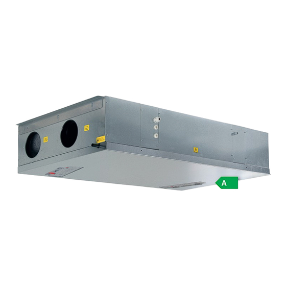
Genvex unit. ECO 190 CS/CL is intended for mounting on the ceiling with special brackets, which is delivered together with the ventilation unit (see photos). - Page 4 ECO 190 CS/CL Dimensions diagram (in mm) 1202 1271 1. Fresh air 2. Exhaust air 3. Extract air 4. Supply air Weight: 25 kg (31 kg with bottom cover plate) ECO 190 TS/TL Dimensions diagram (in mm) 1. Fresh air 2.
-
Page 5: Duct Connection
Duct connection All duct connections display a yellow sticker indicating the type of ventilation duct to be connected. Connect the supply air Du ct system from the unit to the supply outlet in the living room Connect the extract air Duct system from wet rooms to the unit. -
Page 6: Condensate Drain
Condensate drain Insulation of ducts in cold loft spaces The units produce up to 6 litres of condensate per day. It is In order to exploit the unit’s high heat recovery potential therefore important that the condensate drain is correctly (efficiency), it is necessary to insulate the ducts correctly. -
Page 7: Insulation Of Ducts In Heated Spaces
Insulation of ducts in heated spaces Water-based reheating surface To protect the water-based reheating surface from frost Supply and extract ducts burst, a frost protection thermostat must be fitted to the In warm loft spaces the supply and extract channels must unit and the surface insulated. -
Page 8: Electrical Installation
To start up the unit before adjustment, do as follows: Before starting up the unit: 1: Check that the Genvex unit is correctly mounted and that all ducts are insulated as required. 2: Check that hatches can be opened so that service and maintenance on the unit can be carried out. -
Page 9: Optimum Initial Adjustment Of Plant
Optimum initial adjustment of plant Maintenance of ventilation unit Filters Air measuring equipment is used. When the filter timer reaches the set value for filter Before starting initial adjustment, check that the 6 points change, “Alarm!” will show in the screen saver and ”Chg. in the inspection and initial adjustment section have been filter”... -
Page 10: Troubleshooting
After the guarantee period (2 years ->) The installer from whom you have bought the system or the Does not apply to PTC electrical heaters. Genvex service department (+45 7353 2765). Before calling, please write down the data from the The system is not running inscription plate (silver plate on the unit). -
Page 11: Options For Eco 190 Ventilation Unit
OPTIONS FOR ECO 190 VENTILATION UNIT (available upon request from Genvex) Condensate safety float switch - to be wired to "external start/stop" on main PCB for automatic shut down of ventilation unit if condensate drain is blocked. Bottom galvanized steel plate for ECO190C - for a smooth finish of the ECO 190C bottom (available also in white RAL 9016). -
Page 12: Spare Parts
SPARE PARTS Item Description 042478 Optima 251 controller 069300 CS fan complete/069323 CL fan complete 069344 Heat exchanger, aluminium/069345 Heat exchanger, PET 069372 Filter F7 069370 Filter F4 069349 Sealing 069382 Baseplate EPS complete... -
Page 13: Electrical Diagram - Opt251
ELECTRICAL DIAGRAM – OPT251 Q3= 0.5A Q4= 0.5A ES960C Q1= H8,H16,H17 Q2= H6,H7,H9 Q3= L1-L17 Q4= L1-L17 A = LED Flash - Power on B = LED Flash - Communication to Optima Display Q = Fuse L1 = Potential free input for optional: H1 = Mains connection 230 VAC Humidistat, Extractor hood ,CO2... - Page 14 Potential free input for optional: Humidistat, Extractor hood , Optima Design +10V Mains connection 1x230VAC, L-N-PE Max: 13A Sensor, supply air Electric Reheater Sensor, fresh air H2 and H3 Max.load total Sensor, exhaust air 1800W Sensor, extract air Electric Preheater White Signal Red/Brown...
-
Page 15: Electrical Diagram - Opt260
ELECTRICAL DIAGRAM – OPT260 Q3= 0,5A Q4= 0,5A Q1= H8,H14,H16,H17 Q2= H6,H7,H9 Q3= L1-L17 Q4= L1-L17 ES960CC A = LED Flash - Power on B = LED Flash - Startup D = LED Flash - Loads the program from sd card Q = Fuse L1 = Potential free input for optional: H1 =... - Page 16 Potential free input for optional: Humidistat, Extractor hood , Sensor, supply air Sensor, fresh air Sensor, exhaust air Mains connection 1x230VAC, L-N-PE Max: 13A Sensor, extract air White Signal Electric Reheater Red/Brown Humidity sensor Blue/Green H2 and H3 Max.load total Room Sensor 1800W (Optional)
- Page 17 Option 1 Connection for OPT 100 / OPUS control panel OPT 100 DISPLAY Speed button Reheat / Filter reset button LED Speed 1 LED Speed 2 LED Speed 3 LED Speed 4 LED Reheat / Filter alarm Option 2 Connection for boost button and filter reset button Boost button Filter reset button Boost 12V lightbulb...
-
Page 18: Ec - Declaration Of Conformity
ECO 190 CL; TS; TL Ventilation Passive Typ: Ved forudsætning af at Genvex's montageanvisninger er fulgt/ on the assumption that the mounting instruc tions from Genvex have been followed / bei Voraussetzung dass die Montageanweisungen von Genvex gefolgt wurden. Er fremstillet i overensstemmelse med... -
Page 19: Disassembly Instructions
DISASSEMBLY INSTRUCTIONS Remove fans Remove heat exchanger Remove condensate drain switch Remove bypass actuator... - Page 20 – in fact you can recover up to 95% of the heat energy with a Genvex system. Please visit www.genvex.dk to see a list of our distributors KVM-Genvex A/S • Sverigesvej 6 • DK-6100 Haderslev • Tel.: +45 73 53 27 00 • salg@genvex.dk • genvex.dk...
Need help?
Do you have a question about the ECO 190 CS/CL and is the answer not in the manual?
Questions and answers