Table of Contents
Advertisement
Quick Links
Columbia 400 (LC41-550FG)
Information Manual
Revision No. 3 – (November 2004)
THE INFORMATION IN THIS MANUAL WAS TAKEN DIRECTLY
FROM THE FAA APPROVED AIRPLANE FLIGHT MANUAL.
LANCAIR COLUMBIA 400 (LC41-550FG)
SINCE THE DATA IN THE
INFORMATION MANUAL
MAY NOT BE CURRENT AND CANNOT
BE REVISED, THIS MANUAL CANNOT BE USED FOR FLIGHT
OPERATIONS. IT IS NOT A SUBSTITUTE FOR THE OFFICIAL
FAA APPROVED PILOT'S OPERATING HANDBOOK AND
AIRPLANE FLIGHT MANUAL.
The Lancair Company
22550 Nelson Road
Bend Municipal Airport
Bend, Oregon 97701-9710
Phone (541) 318-1144
Fax (541) 318-1177
CustomerService@Lancair.com
http://www.lancair.com/
This document meets GAMA Specification No. 1, Specification for Pilot's Operating
Handbook, issued February 15, 1975 and revised September 1, 1984.
Advertisement
Chapters
Table of Contents

Related Manuals for Lancair Columbia 400


Summary of Contents for Lancair Columbia 400
- Page 1 Information Manual Revision No. 3 – (November 2004) THE INFORMATION IN THIS MANUAL WAS TAKEN DIRECTLY FROM THE FAA APPROVED AIRPLANE FLIGHT MANUAL. LANCAIR COLUMBIA 400 (LC41-550FG) SINCE THE DATA IN THE INFORMATION MANUAL MAY NOT BE CURRENT AND CANNOT BE REVISED, THIS MANUAL CANNOT BE USED FOR FLIGHT OPERATIONS.
- Page 3 TABLE OF SECTIONS SECTION GENERAL ................. 1 LIMITATIONS ..............2 EMERGENCY PROCEDURES ......... 3 NORMAL PROCEDURES ..........4 PERFORMANCE ............... 5 WEIGHT & BALANCE/EQUIPMENT LIST ......6 AIRPLANE & SYSTEMS DESCRIPTION......7 AIRPLANE HANDLING, SERVICE & MAINTENANCE..8 SUPPLEMENTS ..............9...
-
Page 5: Table Of Contents
Section 1 Columbia 400 (LC41-550FG) General Section 1 General TABLE OF CONTENTS THREE-VIEW DRAWING OF THE AIRPLANE..............1-2 INTRODUCTION ........................1-3 DESCRIPTIVE DATA ......................1-4 Engine ..........................1-4 Propeller ..........................1-4 Fuel ............................1-4 Oil ............................1-4 Maximum Certificated Weights ..................1-5 Typical Airplane Weights .................... -
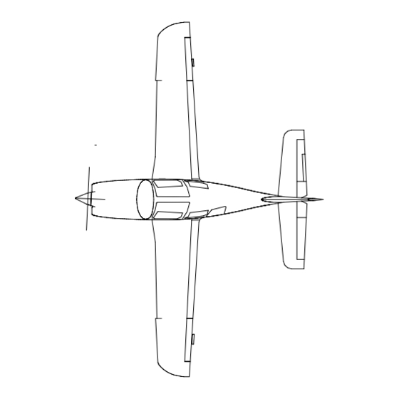
Page 6: Three-View Drawing Of The Airplane
Section 1 General Columbia 400 (LC41-550FG) THREE-VIEW DRAWING OF THE AIRPLANE SPECIFICATIONS Wing Area 141.2 ft. (13.1 m Wing Span 35.8 ft. (10.9 m) Length 25.2 ft. (7.68 m) Empty Weight (±) 2500 lbs. (1134 kg) Gross Weight 3600 lbs. (1633 kg) -
Page 7: Introduction
Section 1 Columbia 400 (LC41-550FG) General Section 1 General INTRODUCTION This handbook is written in nine sections and includes the material required to be furnished to the pilot by Federal Aviation Regulations and additional information provided by the manufac- turer and constitutes the FAA Approved Airplane Flight Manual. Section 1 contains generalized descriptive data about the airplane including dimensions, fuel and oil capacities, and certificated weights. -
Page 8: Descriptive Data
Section 1 General Columbia 400 (LC41-550FG) DESCRIPTIVE DATA ENGINE Number of Engines: 1 Engine Manufacturer: Teledyne Continental Engine Model Number: TSIO-550-C Engine Type: Twin-turbocharged, direct drive, air-cooled, horizontally opposed, fuel-injected, six-cylinder engine with 552 in. (9.0 L) displacement Takeoff Power: 310 BHP at 2600 RPM , 35.5 in of Hg Maximum Continuous Power: 310 BHP at 2600 RPM Maximum Normal Operating Power: 262 BHP (85%) at 2500 RPM, and 33.5 in of Hg... -
Page 9: Maximum Certificated Weights
Section 1 Columbia 400 (LC41-550FG) General Viscosity Recommended for Various Average Air Temperature Ranges Below 40°F (4°C) SAE 30, 10W30, 15W50, or 20W50 Above 40°F (4°C) SAE 50, 15W50, or 20W50 Total Oil Capacity Sump: 8 Quarts (7.6 L) Total: 10 Quarts (9.5 L) -
Page 10: Abbreviations, Terminology, And Symbols
Section 1 General Columbia 400 (LC41-550FG) ABBREVIATIONS, TERMINOLOGY, AND SYMBOLS AIRSPEED TERMINOLOGY Calibrated Airspeed means the indicated speed of an aircraft, corrected for position and instrument error. Calibrated airspeed is equal to true airspeed in standard atmosphere at sea level. -
Page 11: Meteorological Terminology
Section 1 Columbia 400 (LC41-550FG) General Stalling Speed or the minimum steady flight speed at which the airplane is controllable. Stalling Speed or the minimum steady flight speed at which the airplane is controllable in the landing configuration. Best Angle-of-Climb Speed is the airspeed that delivers the greatest gain of altitude in the shortest possible horizontal distance. -
Page 12: Engine Power And Controls Terminology
Section 1 General Columbia 400 (LC41-550FG) Wind The wind velocities recorded as variables on the charts of this handbook are to be understood as the headwind or tailwind components of the reported winds. ENGINE POWER & CONTROLS TERMINOLOGY Brake Horsepower is the power developed by the engine. -
Page 13: Airplane Performance And Flight Planning Terminology
Section 1 Columbia 400 (LC41-550FG) General TIT Gauge The Turbine Inlet Temperature indicator is the instrument used to identify the lean fuel flow mixtures for various power settings. Wing Cuff Specially shaped composite construction on the outboard leading edge of the wing. The cuff increases the camber of the airfoil and improves the slow-flight and stall characteristics of the wing. -
Page 14: Weight And Balance Terminology
Section 1 General Columbia 400 (LC41-550FG) Usable Fuel Usable Fuel is the quantity available that can safely be used for flight planning purposes. WEIGHT AND BALANCE The Arm is the horizontal distance from the reference datum to the center of gravity (C.G.) of an item. - Page 15 Section 1 Columbia 400 (LC41-550FG) General Maximum Zero-Fuel Weight The maximum weight authorized for an aircraft that does not include the weight of the fuel. This weight includes the basic empty weight plus the weight of the passengers and baggage.
-
Page 16: Supplements
Section 1 General Columbia 400 (LC41-550FG) SUPPLEMENTS Equipment, which is not covered in Sections 1 through 8 of the Information Manual, is included in Section 9, as applicable. USE OF THE TERMS WARNING, CAUTION, AND NOTE The following conventions will be used for the terms, Warning, Caution, and Note. -
Page 17: Kilograms And Pounds
Section 1 Columbia 400 (LC41-550FG) General KILOGRAMS AND POUNDS CONVERTING KILOGRAMS TO POUNDS Kilograms 2.205 4.409 6.614 8.818 11.023 13.228 15.432 17.637 19.842 22.046 24.251 26.455 28.660 30.865 33.069 35.274 37.479 39.683 41.888 44.092 46.297 48.502 50.706 52.911 55.116 57.320 59.525... -
Page 18: Feet And Meters
Section 1 General Columbia 400 (LC41-550FG) FEET AND METERS CONVERTING METERS TO FEET Meters 3.281 6.562 9.843 13.123 16.404 19.685 22.966 26.247 29.528 32.808 36.089 39.370 42.651 45.932 49.213 52.493 55.774 59.055 62.336 65.617 68.898 72.178 75.459 78.740 82.021 85.302 88.583... -
Page 19: Inches And Centimeters
Section 1 Columbia 400 (LC41-550FG) General INCHES AND CENTIMETERS CONVERTING CENTIMETERS TO INCHES Centimeters 0.394 0.787 1.181 1.575 1.969 2.362 2.756 3.150 3.543 3.937 4.331 4.724 5.118 5.512 5.906 6.299 6.693 7.087 7.480 7.874 8.268 8.661 9.055 9.449 9.843 10.236 10.630... - Page 20 Section 1 General Columbia 400 (LC41-550FG) NAUTICAL MILES, STATUTE MILES, AND KILOMETERS Nautical Statute Kilo- Nautical Statute Kilo- Nautical Statute Kilo- Miles Miles meters Miles Miles meters Miles Miles meters Figure 1 - 8 RC050002 Initial Issue of Manual: November 10, 2004...
-
Page 21: Liters, Imperial Gallons, And U.s. Gallons
Section 1 Columbia 400 (LC41-550FG) General LITERS, IMPERIAL GALLONS, AND U.S. GALLONS CONVERTING LITERS TO IMPERIAL GALLONS Liters 0.22 0.44 0.66 0.88 1.10 1.32 1.54 1.76 1.98 2.20 2.42 2.64 2.86 3.08 3.30 3.52 3.74 3.96 4.18 4.40 4.62 4.84 5.06... - Page 22 Section 1 General Columbia 400 (LC41-550FG) LITERS, IMPERIAL GALLONS, AND U.S. GALLONS (Continued) CONVERTING LITERS TO U.S. GALLONS Liters 0.00 0.26 0.53 0.79 1.06 1.32 1.59 1.85 2.11 2.38 2.64 2.91 3.17 3.43 3.70 3.96 4.23 4.49 4.76 5.02 5.28 5.55...
- Page 23 Section 1 Columbia 400 (LC41-550FG) General LITERS, IMPERIAL GALLONS, AND U.S. GALLONS (Continued) CONVERTING IMPERIAL GALLONS TO U.S. GALLONS Imperial Gallons 0.00 1.20 2.40 3.60 4.80 6.01 7.21 8.41 9.61 10.81 12.01 13.21 14.41 15.61 16.81 18.02 19.22 20.42 21.62 22.82...
-
Page 24: Temperature Relationship (Fahrenheit And Celsius)
Section 1 General Columbia 400 (LC41-550FG) TEMPERATURE RELATIONSHIPS (FAHRENHEIT AND CELSIUS) Fahrenheit Celsius Fahrenheit Celsius Fahrenheit Celsius -40F -40C 145F 330F 166C -35F -37C 150F 335F 168C -30F -34C 155F 340F 171C -25F -32C 160F 345F 174C -20F -29C 165F... -
Page 25: Fuel Weights And Conversion Relationships
Section 1 Columbia 400 (LC41-550FG) General FUEL WEIGHTS AND CONVERSION RELATIONSHIPS The table below summarizes the weights and conversion relationships for liters, U.S. Gallons, and Imperial Gallons. The chart values are only to two decimal places. The table is intended to provide approximate values for converting from one particular quantity of measurement to another. - Page 26 Section 1 General Columbia 400 (LC41-550FG) This Page Intentionally Left Blank RC050002 Initial Issue of Manual: November 10, 2004 1-22 Latest Revision Level/Date: -/11-10-2004...
- Page 27 Section 2 Columbia 400 (LC41-550FG) Limitations Section 2 Limitations TABLE OF CONTENTS INTRODUCTION ........................2-3 LIMITATIONS..........................2-4 Airspeed Limitation ....................... 2-4 Airspeed Indicator Markings ....................2-4 Powerplant Limitations......................2-5 Powerplant Fuel and Oil Data....................2-5 Oil Grades Recommended for Various Average Temperature Ranges......2-5 Oil Temperature.......................
- Page 28 Section 2 Limitations Columbia 400 (LC41-550FG) PLACARDS..........................2-15 General ..........................2-15 Interior Placards ........................2-15 Exterior Placards ........................2-21 RC050002 Initial Issue of Manual: November 10, 2004 Latest Revision Level/Date: -/11-10-2004...
-
Page 29: Introduction
Section 2 Columbia 400 (LC41-550FG) Limitations Section 2 Limitations INTRODUCTION Section 2 contains the operating limitations of this airplane. The Federal Aviation Administration approves the limitations included in this Section. These include operating limitations, instrument markings, and basic placards necessary for the safe operation of the airplane, the airplane’s engine, the airplane’s standard systems, and the airplane’s standard equipment. -
Page 30: Airspeed Limitation
Section 2 Limitations Columbia 400 (LC41-550FG) LIMITATIONS AIRSPEED LIMITATIONS The airspeed limitations below are based on the maximum gross takeoff weight of 3600 lbs (1633 kg). The maximum operating maneuvering speeds (V ) and applicable gross weight limitations are shown in Figure 2 - 1. -
Page 31: Powerplant Limitations
Section 2 Columbia 400 (LC41-550FG) Limitations POWERPLANT LIMITATIONS Number of Engines: One (1) Engine Manufacturer: Teledyne Continental Engine Model Number: TSIO-550-C Recommended Time Between Overhaul: 2000 Hours (Time in Service) Maximum Power: 310 BHP at 2600 RPM Maximum Manifold Pressure: 35.5 inches of Hg Minimum Power Setting Above 18,000 ft.: 15 inches of Hg and 2200 RPM... -
Page 32: Powerplant Instrument Markings
Section 2 Limitations Columbia 400 (LC41-550FG) POWERPLANT INSTRUMENT MARKINGS The following table, Figure 2 - 3, shows applicable color-coded ranges for the various powerplant instruments. The primary powerplant instruments are located on the engine instrument panel (see discussion on page 7-23). The Engine page on the MFD also displays all the powerplant instruments listed below (see discussion on page 7-83). -
Page 33: Propeller Data And Limitations
Section 2 Columbia 400 (LC41-550FG) Limitations PROPELLER DATA AND LIMITATIONS Number of Propellers: 1 Propeller Manufacture: Hartzell Propeller Hub and Blade Model Numbers: HC-H3YF-1RF and F7693DF Propeller Diameters Minimum: 77 in. (196 cm) Maximum: 78 in. (198 cm) Propeller Blade Angle at 30 inch Station Pressure Low: 16.5°... -
Page 34: Center Of Gravity Table
Section 2 Limitations Columbia 400 (LC41-550FG) CENTER OF GRAVITY TABLE CATEGORY FORWARD DATUM AFT DATUM POINT VARIATION POINT AND WEIGHT AND WEIGHT Utility Category 105 inches at 2600 to 2900 lbs. 112 inches Straight Line 108.8 inches at 3600 lbs. -
Page 35: Flight Load Factor Limits
Section 2 Columbia 400 (LC41-550FG) Limitations WARNING The intentional spinning of the aircraft is prohibited. WARNING If a spin is entered with the flaps extended, they should be retracted after the spin rotation is stopped to avoid exceeding the flap speed limit during recovery. -
Page 36: Avidyne Pfd
Section 2 Limitations Columbia 400 (LC41-550FG) Avidyne PFD Limitations 1. IFR flight is prohibited when the PFD or any mechanical instrument is inoperative (altimeter, airspeed indicator, artificial horizon, or magnetic compass). 2. GPSS mode must not be used on the final approach segment of a VLOC approach (ILS, LOC or non-GPS-overlay VOR). -
Page 37: Transponder Limitations
Section 2 Columbia 400 (LC41-550FG) Limitations NOTE In some areas outside the United States, datums other than WGS-84 or NAD-83 may be used. If the GNS 430 is authorized for use by the appropriate Airworthiness authority, the required geodetic datum must be set in the GNS 430 prior to its use for navigation. -
Page 38: Oxygen Limitations
Section 2 Limitations Columbia 400 (LC41-550FG) OXYGEN LIMITATIONS 1. A4 Flowmeter and standard cannulas may be used for altitudes up to 18,000 ft PA. 2. Cannulas may only be used by persons not experiencing nasal congestion. 3. A4 Flowmeter with oxygen mask may be used for altitudes up to 25,000 ft PA ONLY. -
Page 39: Other Limitations
Section 2 Columbia 400 (LC41-550FG) Limitations using degarbling techniques, the processor can often provide data on the closest threat. In some instances, both aircraft will be decoded, and in other instances, accurate decoding is impossible. This means the traffic may not be displayed on TCAD at all. By keeping the shield size small in high-density areas, the potential for garbled replies is minimized. - Page 40 Section 2 Limitations Columbia 400 (LC41-550FG) This Page Intentionally Left Blank RC050002 Initial Issue of Manual: November 10, 2004 2-14 Latest Revision Level/Date: -/11-10-2004...
-
Page 41: Placards
Section 2 Columbia 400 (LC41-550FG) Limitations PLACARDS GENERAL Federal Aviation Regulations require that a number of different placards be prominently displayed on the interior and exterior of the airplane. The placards contain information about the airplane and its operation that is of significant importance. The placard is placed in a location proximate to the item it describes. - Page 42 Section 2 Limitations Columbia 400 (LC41-550FG) Near Pilot and Copilot Interior Door Handles Near Door Handle on Passenger Side On Baggage Compartment Door Joggle RC050002 Initial Issue of Manual: November 10, 2004 2-16 Latest Revision Level/Date: A/12-01-2004...
- Page 43 Section 2 Columbia 400 (LC41-550FG) Limitations On Crash Ax In Aft Cabin on Aft Baggage Bulkhead Under Left Rear Seat Next to Leveling Washer Under All Seats On Parking Brake Handle Initial Issue of Manual: November 10, 2004 RC050002 Latest Revision Level/Date: A/12-01-2004...
- Page 44 Section 2 Limitations Columbia 400 (LC41-550FG) Near Airspeed Indicator 158 KIAS (3600 LBS) 135 KIAS (2600 LBS) Near Airspeed Indicator 4.4 KIAS/1000 FT 3.5 KIAS/1000 FT On Flap Panel NO FLAPS OPERATION ABOVE 14,000 FT. PA On Center Overhead Console The magnetic direction indicator is calibrated for level flight with the engine, radios, and strobes operating.
- Page 45 Section 2 Columbia 400 (LC41-550FG) Limitations Above Copilot's Fresh Air Vent On Top Center of Engine Instrument Panel (when autopilot installed) On Engine Instrument Panel Under CHT/TIT Gauge On Top Center of Flight Instrument Panel (when autopilot installed) Near the Left Dimmer Switch on the Pilot’s Knee Bolster...
- Page 46 Section 2 Limitations Columbia 400 (LC41-550FG) Engraved On Fuel Selector Knob and Upper Plate LEFT RIGHT On Oxygen Distribution Manifold in Forward Overhead Panel On Oxygen Fill Port Set into Hat Shelf RC050002 Initial Issue of Manual: November 10, 2004...
-
Page 47: Exterior Placards
Section 2 Columbia 400 (LC41-550FG) Limitations EXTERIOR PLACARDS On Oil Filler Access Door Near Pilot and Passenger Door Handles On Main Wheel Pants On Nose Gear Wheel Pant or Nose Gear Fairing (if nose gear wheel pant not installed) On Flaps Near Wing Root (Both Sides) - Page 48 Section 2 Limitations Columbia 400 (LC41-550FG) Near Fill Cap of Fuel Tank Under Each Wing Near Fuel Drains FOR DRAINING OF WING FUEL SUMP: TO OPEN: PRESS CUP GENTLY INTO BOTTOM OF VALVE TO DRAIN REQUIRED AMOUNT OF FUEL. TO CLOSE: REMOVE CUP AND VALVE WILL CLOSE.
- Page 49 Section 2 Columbia 400 (LC41-550FG) Limitations On Left Side Wing Fillet On Exterior of Fuselage – Forward of Wing on Pilot’s Side Initial Issue of Manual: November 10, 2004 RC050002 Latest Revision Level/Date: -/11-10-2004 2-23...
- Page 50 Section 2 Limitations Columbia 400 (LC41-550FG) On Exterior of Fuselage – Forward of Wing on Copilot’s Side On Forward Portion of Nose Gear Fairing TURN LIMIT On Nose Gear Wheel Pant (if installed) RC050002 Initial Issue of Manual: November 10, 2004...
-
Page 51: Emergency Procedures
Section 3 Columbia 400 (LC41-550FG) Emergency Procedures Section 3 Emergency Procedures TABLE OF CONTENTS INTRODUCTION ........................3-5 Airspeeds for Emergency Operations ..................3-5 EMERGENCY PROCEDURES CHECKLISTS ................ 3-6 Engine Failure During Takeoff....................3-6 Engine Failure Immediately After Takeoff (Below 400 feet AGL) ........3-6 Engine Failure During Climb to Cruise Altitude (Above 400 feet AGL) ...... - Page 52 Section 3 Emergency Procedures Columbia 400 (LC41-550FG) AMPLIFIED EMERGENCY PROCEDURES ................. 3-20 Engine Failure and Forced Landings ................... 3-20 General ........................... 3-20 Engine Failure After Takeoff (Below 400 feet AGL)............ 3-20 Engine Failure After Takeoff (Above 400 feet AGL) ........... 3-20 In-Flight Engine Failure....................
- Page 53 Section 3 Columbia 400 (LC41-550FG) Emergency Procedures Emergency Exit ........................3-34 General........................... 3-34 Doors..........................3-34 Seat Belts ........................3-34 Exiting (Cabin Door(s) Operable) ................. 3-34 Exiting (Cabin Doors Inoperable) ................. 3-34 Inverted Exit Procedures...................... 3-34 General........................... 3-34 Exterior Emergency Exit Release.................. 3-35 Crash Ax ..........................
- Page 54 Section 3 Emergency Procedures Columbia 400 (LC41-550FG) This Page Intentionally Left Blank RC050002 Initial Issue of Manual: November 10, 2004 Latest Revision Level/Date: -/11-10-2004...
-
Page 55: Introduction
Section 3 Columbia 400 (LC41-550FG) Emergency Procedures Section 3 Emergency Procedures INTRODUCTION The emergency procedures are included before the normal procedures, as these items have a higher level of importance. The owner of this handbook is encouraged to copy or otherwise tabulate the following emergency procedures in a format that is usable under flight conditions. -
Page 56: Emergency Procedures Checklists
Section 3 Emergency Procedures Columbia 400 (LC41-550FG) EMERGENCY PROCEDURES CHECKLISTS ENGINE FAILURE DURING TAKEOFF 1. Throttle Control SET TO IDLE 2. Brakes APPLY STEADY PRESSURE (release momentarily if skidding occurs) 3. Wing Flaps IN THE UP POSITION 4. -
Page 57: Engine Failure During Flight Above 15,000 Ft
Section 3 Columbia 400 (LC41-550FG) Emergency Procedures 5.2. Engine Restarts Use the Procedures After an Engine Restart checklist. 6. Ignition Switch VERIFY SET TO R/L ENGINE FAILURE DURING FLIGHT ABOVE 15,000 FT 1. Airspeed 108 KIAS (flaps in the up position) 2. -
Page 58: Engine Failure With Fuel Annunciator Illuminated Below 15,000 Ft
Section 3 Emergency Procedures Columbia 400 (LC41-550FG) ENGINE FAILURE WITH FUEL ANNUNCIATOR ILLUMINATED BELOW 15,000 FT 1. Airspeed 82 to 108 KIAS - See Figure 3 - 3. 2. Mixture Control SET TO RICH 3. Throttle Control ADVANCED ABOUT ONE THIRD 4. -
Page 59: Emergency Landing Without Engine Power
Section 3 Columbia 400 (LC41-550FG) Emergency Procedures power to 75% or less and land as soon as possible. Do not set the mixture too rich for descent or landing. Refer to the amplified discussion on page 3-21. 3.3. Improper Mixture Setting If fuel management is correct and the engine driven fuel pump is working properly, it is possible the mixture is either too lean or too rich. -
Page 60: Precautionary Landing With Engine Power
WARNING Two special conditions associated with forced landings are specifically applicable to the Columbia 400 (and are different from many other General Aviation airplanes). These differences must be clearly understood. 1. Because the trim tabs and flaps are electrically operated, setting the... -
Page 61: Engine Driven Fuel Pump (Edfp) - Partial Failure
Section 3 Columbia 400 (LC41-550FG) Emergency Procedures ENGINE DRIVEN FUEL PUMP (EDFP) – PARTIAL FAILURE (Fuel pressure too high to activate backup pump. Intermittent power – No fuel pump annunciator) 1. Backup Boost Pump SET TO ARMED 2. Throttle Control SET TO FULL OPEN 3. -
Page 62: Engine Fire On The Ground During Startup
Section 3 Emergency Procedures Columbia 400 (LC41-550FG) NOTE In situations that require electrical system shutdown under poor ambient light conditions, cabin illumination is available through use of the overhead flip lights. The flip lights are connected directly to the battery and will operate provided there is adequate battery power. -
Page 63: In-Flight Cabin Fire (Fuel/Hydraulic Fluid)
Section 3 Columbia 400 (LC41-550FG) Emergency Procedures 8. Post Fire Details OPEN VENTILATION (if fire is extinguished) 9. Nav/Com Bypass Switch SET TO ON 10. Phased System Power-upDetermine if electrical power is necessary for the safe continuation of the flight. If it is required, proceed with items 11 through 13 below. -
Page 64: Inadvertent Icing
Section 3 Emergency Procedures Columbia 400 (LC41-550FG) WARNING Recovery from a spin may require up to one additional turn with normal use of controls for recovery. WARNING If a steady state spin is entered, holding the recommended recovery inputs of power idle, rudder full against the spin, elevator full forward and aileron full against the spin will produce the fastest recovery. -
Page 65: Landing With Flat Main Tire
Section 3 Columbia 400 (LC41-550FG) Emergency Procedures LANDING WITH A FLAT MAIN TIRE 1. Approach NORMAL 2. Wing Flaps SET TO LANDING POSITION 3. Touchdown Touch down on the inflated tire first and maintain full aileron deflection towards the good tire, keeping the flat tire off the ground for as long as possible. Be prepared for abnormal yaw in the direction of the flat tire. -
Page 66: Left Or Right Bus Failure/Crosstie Discharges Working Bus
Section 3 Emergency Procedures Columbia 400 (LC41-550FG) 3.2. Alternator Annunciator Light On If after recycling the system the alternator annunciator light does not go out or trips the alternator off-line again, follow steps 4 - 6 below. 4. Affected Alternator Master Switch SET TO OFF 5. -
Page 67: Partial Restoration Of Disabled Trim System
Section 3 Columbia 400 (LC41-550FG) Emergency Procedures control without pilot input to the affected flight control(s). If excessive control force is required to maintain level flight, land as soon as possible. Pilot fatigue can be increased significantly in this situation with the potential for making the landing difficult. -
Page 68: Oxygen System Malfunction
Section 3 Emergency Procedures Columbia 400 (LC41-550FG) OXYGEN SYSTEM MALFUNCTION 1. Flow Meters VERIFY FLOW TO BREATHING DEVICES 2. Descend 12,500 ft or below (In a safe and controlled manner) 3. Oxygen Switch SET TO OFF NOTE When the oxygen switch is turned on, oxygen system malfunctions will be indicated by the illuminated oxygen annunciator. -
Page 69: Circuit Breaker Panel
Section 3 Columbia 400 (LC41-550FG) Emergency Procedures CIRCUIT BREAKER PANEL Many of the above emergency procedures involve resetting or pulling circuit breakers, which requires a good understanding of the panel’s location and layout. The circuit breaker panel is located forward of the pilot’s front seat on the lower side-panel. To ensure the pilot knows the location of each circuit breaker, a picture of the circuit breaker panel and a table listing each circuit breaker is provided in Figure 3 - 2. -
Page 70: Amplified Emergency Procedures
Section 3 Emergency Procedures Columbia 400 (LC41-550FG) AMPLIFIED EMERGENCY PROCEDURES ENGINE FAILURE AND FORCED LANDINGS General – The most important thing in any emergency is to maintain control of the airplane. If an engine failure occurs during the takeoff run, the primary consideration is to safely stop the airplane in the remaining available runway. -
Page 71: Best Glide Speed Versus Minimum Rate Of Descent Speed
Section 3 Columbia 400 (LC41-550FG) Emergency Procedures Best Glide Speed Versus Minimum Rate of Descent Speed – The best distance glide speed will provide the most distance covered over the ground for a given altitude loss, while the minimum rate of descent speed, as its name suggests, will provide the least altitude lost in a given time period. - Page 72 Section 3 Emergency Procedures Columbia 400 (LC41-550FG) stoppage. If the engine failure is a result of fuel starvation with a fuel pressure less than 5.5 psi, then the FUEL annunciator will provide a visual indication. There is a latching relay that basically controls the logic of the system. For example, it turns the backup pump on, when the backup boost switch is in the ARMED position and the fuel pressure drops below 5.5 psi.
-
Page 73: Engine Restarts
Section 3 Columbia 400 (LC41-550FG) Emergency Procedures Engine Restarts – If the engine restarts, two special issues must be considered: (1) If the airplane was in a glide for an extended period of time at cold ambient air temperatures, the engine should be operated at lower RPM settings for a few minutes until the oil and cylinder temperatures return to normal ranges if possible. -
Page 74: Elevator Failure
Section 3 Emergency Procedures Columbia 400 (LC41-550FG) inherent in such an approach will increase the airplane’s stall speed, and a margin for safety should be added to the approach airspeed. Elevator Failure – In the event of a failure of the elevator control system, the airplane can be controlled and landed using the elevator trim tab. -
Page 75: Fires
400’s electrical system. This surge protection comes from large MOVs (metal oxide varistor) soldered in behind the circuit breaker panel. The Columbia 400 system has one MOV on the avionics bus and one on the essential bus. The MOVs are located behind the circuit breaker panel and are not accessible by the pilot in-flight. -
Page 76: Engine And Propeller Problems
Section 3 Emergency Procedures Columbia 400 (LC41-550FG) If the aircraft is struck by lightning in flight, the MOVs will have likely prevented significant damage to the electrical components. The most likely damage will be to the equipment on the extreme ends of the airplane, such as the strobe and anti-collision lights. After the lightning strike, the pilot should reset all tripped circuit breakers. -
Page 77: Low Oil Pressure
Section 3 Columbia 400 (LC41-550FG) Emergency Procedures CAUTION If the above steps do not restore oil temperature to normal, severe damage or an engine failure can result. Reduce power to idle, and select a suitable area for a forced landing. Follow the procedures described on page 3-9, Emergency Landing Without Engine Power. -
Page 78: Propeller Surging Or Wandering
Section 3 Emergency Procedures Columbia 400 (LC41-550FG) arming is normally in the OFF position. At the first indication of engine driven pump failure (fuel pump warning annunciator, low fuel pressure, or rough engine operations), set the throttle to full open, and set the backup pump switch to the ARMED position. Thereafter, it must remain in this position and a landing must be made as soon as practicable to repair the engine driven boost pump. -
Page 79: Alternator Failure
Section 3 Columbia 400 (LC41-550FG) Emergency Procedures battery carries the entire electrical demand of the affected bus. As the battery charge is expended, the voltage to the system will read something less than the optimum 14.2 volts. At approximately 8 volts, most electrical components on the affected bus will cease to work or will operate erratically and unreliably. -
Page 80: Complete Left Or Right Bus Failure
Section 3 Emergency Procedures Columbia 400 (LC41-550FG) COMPLETE LEFT OR RIGHT BUS FAILURE General – Normally, a pilot can anticipate the onset of a complete electrical failure. Items like an alternator failure and a battery discharging state usually precedes the total loss of electrical power on the left or right bus. -
Page 81: Summary Of Buses
Section 3 Columbia 400 (LC41-550FG) Emergency Procedures SUMMARY OF BUSES Bus Component Circuit Breaker Audio/Voice 5 amp • GPS 1 5 amp • GPS 2 5 amp • Nav/Com #1 10 amp • Com #2 10 amp • Transponder/Encoder and Equipment Fan 5 amp •... -
Page 82: Spins
Section 3 Emergency Procedures Columbia 400 (LC41-550FG) left dimmer control and is labeled ALT STATIC. To access the alternate static source, rotate the static control knob clockwise until it locks in the ALT position. When the alternate static source is in use, the indications of the airspeed indicator and altimeter will vary slightly. Airspeed calibration charts are in Section 5 and begin on page 5-2. -
Page 83: Autopilot
Section 3 Columbia 400 (LC41-550FG) Emergency Procedures Loss of air data (altitude, airspeed) is indicated by the affected indicator being removed from the display and replaced with a red X. Loss of attitude data (pitch, roll, heading) is indicated by the affected indicator being removed from the display and replaced with a red X. -
Page 84: Emergency Exit
Section 3 Emergency Procedures Columbia 400 (LC41-550FG) Failures that the pilot may rectify in flight are leaks downstream of the distribution manifold, which may consist of misadjusted or pinched flexible lines, or replacement of failed flow devices in the system. These failures can be indicated by the outlet pressure display at the bottom of the oxygen panel and by inadequate flows as indicated by the flow meter or flow indicators. -
Page 85: Exterior Emergency Exit Release
Section 4 Columbia 400 (LC41-550FG) Normal Procedures 1. Release the seat belt. The pilot should position himself or herself in a manner that minimizes injury before releasing the seat belt. 2. Remove crash ax from its holder. 3. If the airplane is situated with one wing down and touching the ground and one wing up, break the cabin door window on the up-wing side. -
Page 86: Crash Ax
Section 4 Normal Procedures Columbia 400 (LC41-550FG) CRASH AX A crash ax is located under the pilot’s seat for use in the event the cabin door and the emergency door releases cannot be used. The blade of the ax points down and is inserted in an aluminum sheath, and the unit is secured with a Velcro strip. - Page 87 Section 4 Columbia 400 (LC41-550FG) Normal Procedures Section 4 Normal Procedures TABLE OF CONTENTS INTRODUCTION .......................... 4-4 Indicated Airspeeds for Normal Operations ................4-5 NORMAL PROCEDURES CHECKLISTS................... 4-6 Preflight Inspection........................4-6 Before Starting Engine ......................4-8 Starting Engine ......................... 4-9 After Engine Start ........................
- Page 88 Section 4 Normal Procedures Columbia 400 (LC41-550FG) Before Starting Engine......................4-21 Fresh Air Vents ........................4-21 Three Point Restraints (Seat Belts and Shoulder Harnesses)..........4-21 Child Restraints........................4-21 Engine Starting.........................4-22 Normal Starting........................4-22 Under Priming........................4-22 Over Priming........................4-23 Battery Recharging ........................4-23 Ground Power Operations....................4-23 Right Battery Inoperative....................4-23 Left Battery Inoperative .....................4-24...
- Page 89 Section 4 Columbia 400 (LC41-550FG) Normal Procedures Practicing Stalls ......................... 4-32 Loading and Stall Characteristics ..................4-33 Spins ............................4-33 Cold Weather Operations ......................4-33 Hot Weather Operations ......................4-35 Noise Abatement ........................4-36 Initial Issue of Manual: November 10, 2004...
- Page 90 Section 4 Normal Procedures Columbia 400 (LC41-550FG) This Page Intentionally Left Blank RC050002 Initial Issue of Manual: November 10, 2004 Latest Revision Level/Date: -/11-10-2004...
-
Page 91: Introduction
Section 4 Columbia 400 (LC41-550FG) Normal Procedures Section 4 Normal Procedures INTRODUCTION Section 4 contains checklists for normal procedures. As mentioned in Section 3, the owner of this handbook is encouraged to copy or otherwise tabulate the following normal procedures checklists in a format that is usable under flight conditions. -
Page 92: Normal Procedures Checklists
Section 4 Normal Procedures Columbia 400 (LC41-550FG) NORMAL PROCEDURES CHECKLISTS PREFLIGHT INSPECTION Figure 4-2 depicts the major inspection points, and the arrow shows the sequence for inspecting each point. The inspection sequence in Figure 4 - 2 runs in a clockwise direction; however, it does not matter in which direction the pilot performs the preflight inspection so long as it is systematic. - Page 93 Section 4 Columbia 400 (LC41-550FG) Normal Procedures NOTE The heated pitot housing should be warm to the touch in a minute or so, and it should not be operated for more than one to two minutes when the airplane is in the static condition. For this reason the operational check must be performed out of sequence.
-
Page 94: Before Starting Engine
Section 4 Normal Procedures Columbia 400 (LC41-550FG) Area 5 (Right Wing Leading Edge, Fuel Tank, Right Tire) 1. Wing Fuel Drain CHECK FOR CONTAMINATION (Preceding first flight of the day or after refueling.) 2. Right Main Strut and Tire CHECK (Remove wheel chocks, check tire for proper inflation, check gear strut for evidence of damage.) -
Page 95: Starting Engine
Section 4 Columbia 400 (LC41-550FG) Normal Procedures 8. Brakes TESTED AND SET 9. All Circuit Breakers CHECK IN 10. Left Bus Switch SET TO ON 11. Oxygen Switch SET TO DISP 12. Oxygen Quantity NOTE 13. -
Page 96: Starting Engine With Ground Power Cart
Section 4 Normal Procedures Columbia 400 (LC41-550FG) STARTING ENGINE WITH GROUND POWER CART 1. Left and Right Master Switches VERIFY OFF 2. Check Propeller Area CLEAR (Ensure people/equipment are not in the propeller area.) 3. Auxiliary Power Plug CONNECT POWER PLUG (Use a 12 volt DC source) 4. -
Page 97: Crosstie Operation
Section 4 Columbia 400 (LC41-550FG) Normal Procedures CROSSTIE OPERATION 1. Left Battery Bus Switch SET TO OFF (Ensure the essential and avionics buses are energized) 2. L BUS OFF Annunciator ILLUMINATED 3. Crosstie Switch SET TO ON (Ensure right ammeter is showing charge and load increase for left and right buses) 4. -
Page 98: Before Taxi
Section 4 Normal Procedures Columbia 400 (LC41-550FG) BEFORE TAXI 1. Engine Instruments CHECK (Within proper ranges) 2. Fuel Gauges CHECK PROPER INDICATION 3. Wing Flaps SET TO UP (Cruise Position) 4. Ammeters CHARGING 5. Radio Clearance AS REQUIRED 6. - Page 99 Section 4 Columbia 400 (LC41-550FG) Normal Procedures 27. Annunciator Panel ALL LIGHTS OFF 28. Door Seals ON 29. Backup Boost Pump ARMED 30. Oxygen Switch SET TO ON 31. Mask or Cannula DON 32. Flowmeters CHECK AND ADJUST TO PLANNED CRUISE ALTITUDE (ensure that the internal metering ball moves freely and oxygen is flowing to the delivery devices) 33.
-
Page 100: Minor Spark Plug Fouling
Section 4 Normal Procedures Columbia 400 (LC41-550FG) MINOR SPARK PLUG FOULING (Minor plug fouling can usually be cleared as follows.) 1. Throttle/Brakes HOLD BRAKES MANUALLY AND SET THROTTLE TO 2200 RPM 2. Mixture ADJUST FOR MAXIMUM PERFORMANCE (Move towards idle cutoff until RPM peaks, and hold for 10 seconds. -
Page 101: Crosswind Operations
Section 4 Columbia 400 (LC41-550FG) Normal Procedures CROSSWIND OPERATIONS Crosswind takeoffs and landings require a special technique but not specific procedures and, as such, do not require a dedicated checklist. Please see the amplified discussion on pages 4-27 and 4-32 for applicable crosswind techniques. -
Page 102: Descent
Section 4 Normal Procedures Columbia 400 (LC41-550FG) leaning the mixture. Above 18,000 ft. the minimum manifold pressure is 15 in. Hg; minimum RPM is 2,200. NOTE The vapor suppression must be turned on before changing the selected fuel tank. After proper engine operations are established, the pump is turned off. -
Page 103: Normal Landing
Section 4 Columbia 400 (LC41-550FG) Normal Procedures NORMAL LANDING 1. Approach Airspeed AS REQUIRED FOR CONFIGURATION Flaps (Cruise Position) ..105 to 110 KIAS Flaps (Landing Position) ..85 to 90 KIAS 2. Trim Tabs (2) ADJUST AS REQUIRED 3. -
Page 104: Shutdown
Section 4 Normal Procedures Columbia 400 (LC41-550FG) SHUTDOWN 1. Parking Brake SET 2. Throttle SET TO IDLE (900 RPM) 3. Autopilot SET TO OFF 4. Oxygen SET TO OFF 5. ELT CHECK NOT ACTIVATED (Check before shutdown) 6. -
Page 105: Amplified Procedures
Section 4 Columbia 400 (LC41-550FG) Normal Procedures AMPLIFIED PROCEDURES PREFLIGHT INSPECTION The purpose of the preflight inspection is to ascertain that the airplane is physically capable of completing the intended operation with a high degree of safety. The weather conditions, length of flight, equipment installed, and daylight conditions, to mention a few, will dictate any special considerations that should be employed. -
Page 106: Stall Warning Vane
FUEL QUANTITY The Columbia 400 fuel quantity measuring system described on page 7-52 provides a fairly accurate indication of the onboard fuel. The system has two sensors in each tank, and flat spots in the indicating system are minimized. Still, the gauges must never be used in place of a visual inspection of each tank. -
Page 107: Static Wicks
The static wicks are designed to discharge accumulated static electricity created by the airplane’s movement through the air. Because the Columbia 400 (LC41-550FG) cruises at high speeds, the wicks are the solid type with a carbon interior and a plastic exterior. The static wick can be broken without obvious exterior indications. -
Page 108: Engine Starting
Section 4 Normal Procedures Columbia 400 (LC41-550FG) second birthday and does not occupy or use any restraining device. If a restraining device is used, the FARs require a type approved under one of the following conditions. 1. Seats manufactured to U.S. standards between January 1, 1981, and February 25, 1985 must bear the label: “This child restraint system conforms to all applicable federal motor vehicle... -
Page 109: Over Priming
Section 4 Columbia 400 (LC41-550FG) Normal Procedures Over Priming – If the engine starts intermittently and is followed by puffs of black smoke, over priming is the most likely cause. The black smoke means the mixture is too rich and the engine is burning off the excess fuel. -
Page 110: Left Battery Inoperative
Section 4 Normal Procedures Columbia 400 (LC41-550FG) engaged, it will only energize the left starter contactor, since there is no battery power to energize the right contactor. Once the engine is running, the crosstie switch must be turned on to charge the right battery. -
Page 111: Taxiing
Section 4 Columbia 400 (LC41-550FG) Normal Procedures around the perimeter of the doorframe will remove enough pieces so that the middle portion of the window can be removed with a few heavy blows. Once the major portion of the window is removed and if time and circumstances permit, use the ax blade to smooth down the jagged edges around the doorframe. -
Page 112: Before Takeoff
Section 4 Normal Procedures Columbia 400 (LC41-550FG) BEFORE TAKEOFF Engine Temperatures – The control of engine temperatures is an important consideration when operating the airplane on the ground. The efficient aerodynamic design and closely contoured cowling around the engine maximizes cooling in flight. However, care must be used to preclude overheating during ground operations. -
Page 113: Short Field Takeoff
Section 4 Columbia 400 (LC41-550FG) Normal Procedures Short Field Takeoff – The three major items of importance in a short field takeoff are developing maximum takeoff power, maximum acceleration, and utilization of the entire runway available. Be sure the mixture is properly set for takeoff if operating from a high altitude airport. -
Page 114: Power Settings
Section 4 Normal Procedures Columbia 400 (LC41-550FG) Power Settings – Use maximum continuous power until the airplane reaches a safe altitude above the ground. Ensure the propeller RPM does not exceed the red line limitation. It is recommended to use full throttle and 2600 RPM in climb because this setting provides the engine with extra fuel for cooling at the slower airspeeds. -
Page 115: Mixture Settings
Section 4 Columbia 400 (LC41-550FG) Normal Procedures flight. Section 5 in this manual contains detailed information to assist the pilot in the flight planning process. In general, the airplane cruises at 50% to 85% of available power. The maximum recommended cruise power setting is 85%. -
Page 116: Door Seals
Section 4 Normal Procedures Columbia 400 (LC41-550FG) Door Seals – Normally, the door seal switch remains in the On position for the entire flight. If the system pressure drops below 12 psi, the air pump will cycle on until pressure is restored. If the pump runs continuously, it is an indication that a seal is damaged and incapable of holding pressure. -
Page 117: Approach
Section 4 Columbia 400 (LC41-550FG) Normal Procedures APPROACH On the downwind leg, adjust power to maintain 110 KIAS to 120 KIAS with the flaps retracted. When opposite the landing point, reduce power, set the flaps to the takeoff position, and reduce speed to about 90 KIAS. -
Page 118: Crosswind Landings
Section 4 Normal Procedures Columbia 400 (LC41-550FG) attitude on the main landing gear first. Lower the nose wheel smoothly and quickly, and apply heavy braking. However, do not skid the tires. Braking response is improved if the flaps are retracted after touchdown. -
Page 119: Loading And Stall Characteristics
CG. However, as the center of gravity moves aft, the stall handling characteristics, in terms of lateral stability, will deteriorate. On the Columbia 400, it is particularly noticeable at higher power settings with flaps in the landing position. Lateral loading is also an issue, particularly with an aft CG. - Page 120 Section 4 Normal Procedures Columbia 400 (LC41-550FG) complicating the starting procedure. False starting (failure to continue running after starting) often results in the formation of moisture on spark plugs due to condensation. This moisture can freeze and must be eliminated either by applying heat to the engine or removing and cleaning the spark plugs.
-
Page 121: Hot Weather Operations
Section 4 Columbia 400 (LC41-550FG) Normal Procedures After starting the engine, set the idle to 1000 RPM or less until an increase in oil temperature is noted. Since the oil in the oil pressure gauge line may be congealed, as much as 30 seconds may elapse before oil pressure is indicated. -
Page 122: Noise Abatement
The certificated level for the Columbia 400 (LC41-550FG) at 3600 lbs. (1633 kg) gross weight is 81.5 dB(A). The FAA has made no determination that these noise levels are acceptable or unacceptable for operations at any airport. - Page 123 Section 5 Columbia 400 (LC41-550FG) Performance Section 5 Performance TABLE OF CONTENTS INTRODUCTION ........................5-2 Airspeed Calibration (Flaps Up Position)..................5-3 Airspeed Calibration (Flaps Takeoff Position)................5-3 Airspeed Calibration (Flaps Landing Position) ................5-4 Equivalent Airspeed Calibration 12,000 ft .................. 5-4 Equivalent Airspeed Calibration 18,000 ft ..................
-
Page 124: Introduction
Section 5 Performance Columbia 400 (LC41-550FG) INTRODUCTION The performance charts and graphs on the following pages are designed to assist the pilot in determining specific performance characteristics in all phases of flight operations. These phases include takeoff, climb, cruise, descent, and landing. The data in these charts were determined through actual flight tests of the airplane. - Page 125 Section 5 Columbia 400 (LC41-550FG) Performance Airspeed Calibration – Normal and Alternate Static Source Flaps – Up Position (0°) Example: 157 KIAS is equal to 152 KCAS when using the alternate static source. Alternate Static Source Normal Static Source Knots Calibrated Airspeed (KCAS) Figure 5 - 2 Airspeed Calibration –...
-
Page 126: Equivalent Airspeed Calibration 12,000 Ft
Section 5 Performance Columbia 400 (LC41-550FG) Airspeed Calibration – Normal and Alternate Static Source Flaps – Landing Position (40°) Example: 70 KIAS is equal to 71 KCAS when using the normal static source. Normal Static Source Alternate Static Source Knots Calibrated Airspeed (KCAS) -
Page 127: Equivalent Airspeed Calibration 18,000 Ft
Section 5 Columbia 400 (LC41-550FG) Performance Equivalent Airspeed Calibration 18,000 ft Knots Equivalent Airspeed (KEAS) Figure 5 - 6 Initial Issue of Manual: November 10, 2004 RC050002 Latest Revision Level/Date: -/11-10-2004... -
Page 128: Temperature Conversion
Section 5 Performance Columbia 400 (LC41-550FG) TEMPERATURE CONVERSION TEMPERATURE CONVERSION --40 Figure 5 - 7 FAHRENHEIT STALL SPEEDS Figure 5 - 8 shows the stalling speed of the airplane for various flap settings and angles of bank. To provide a factor of safety, the tabulated speeds are established using maximum gross weight and the most forward center of gravity (CG), i.e., 3600 pounds with the CG located 108.8 inches... -
Page 129: Speedbrakes
Section 5 Columbia 400 (LC41-550FG) Performance with a forward CG are noticeably diminished. Please see stall discussion on page 4-32. The maximum altitude loss during power off stalls is about 500 feet. Nose down attitude change during stall recovery is generally less than 5° but may be up to 15°. Example: Using the table below, stall speeds of 64 KIAS and 65 KCAS are indicated for 30°... -
Page 130: Crosswind, Headwind, And Tailwind Component
Section 5 Performance Columbia 400 (LC41-550FG) CROSSWIND, HEADWIND, AND TAILWIND COMPONENT 10º 20º 30º 40º 50º 60º 70º 80º Component Component Component Component Component Component Component Component in knots of in knots of in knots of in knots of in knots of... -
Page 131: Short Field Takeoff Distance (12º - Takeoff Flaps)
Section 5 Columbia 400 (LC41-550FG) Performance SHORT FIELD TAKEOFF DISTANCE (12º - TAKEOFF FLAPS) ASSOCIATED CONDITIONS EXAMPLE Power Takeoff Power Set Before Brake Release 25°C Flaps 12° (Takeoff position) Pressure Altitude (PA) 4000 ft Runway Paved, Level, Dry Surface Takeoff Weight... -
Page 132: Takeoff Speed Schedule
Section 5 Performance Columbia 400 (LC41-550FG) TAKEOFF SPEED SCHEDULE The following chart should be used in conjunction with the takeoff distance chart in Figure 5 - 10 to determine the proper takeoff speed based on aircraft weight. Takeoff Speed Schedule Speed at 50 ft. -
Page 133: Maximum Rate Of Climb
Section 5 Columbia 400 (LC41-550FG) Performance MAXIMUM RATE OF CLIMB RATE OF CLIMB RATE OF CLIMB RATE OF CLIMB (FT/MIN) (FT/MIN) (FT/MIN) Pressure 3000 lb (1361 kg) 3300 lb (1497 kg) 3600 lb (1633 kg) Altitude 106 KIAS 108 KTAS... -
Page 134: Time, Fuel, And Distance To Climb
Section 5 Performance Columbia 400 (LC41-550FG) TIME, FUEL, AND DISTANCE TO CLIMB Rate of Pressure Climb Speed Time Fuel Used Distance Climb Altitude KIAS Gal. (L) 25000 19.2 11.5 (43.5) 24000 18.2 10.9 (41.3) 23000 1053 17.2 10.3 (39.0) 22000 1117 16.3... -
Page 135: Cruise Performance Overview
Section 5 Columbia 400 (LC41-550FG) Performance CRUISE PERFORMANCE OVERVIEW The tables on pages 5-14 through 5-27 contain cruise data to assist in the flight planning process. This information is tabulated for even thousand altitude increments and ranges from Sea Level feet to 25,000 feet. -
Page 136: Cruise Performance Sea Level Pressure Altitude
Section 5 Performance Columbia 400 (LC41-550FG) CRUISE PERFORMANCE SEA LEVEL PRESSURE ALTITUDE -5°C 15°C 45°C (Standard Temperature) (20°C Below Standard) (30°C Above Standard) % BHP KTAS % BHP KTAS % BHP KTAS 2500 31.5 2400 2300 3600 lbs. (1633 kg) Gross Weight Recommended Mixture Setting. - Page 137 Section 5 Columbia 400 (LC41-550FG) Performance CRUISE PERFORMANCE 2000 FEET PRESSURE ALTITUDE -9°C 11°C 41°C (Standard Temperature) (20°C Below Standard) (30°C Above Standard) % BHP KTAS % BHP KTAS % BHP KTAS 2500 31.5 2400 2300 3600 lbs. (1633 kg) Gross Weight Recommended Mixture Setting.
-
Page 138: Cruise Performance 4000 Ft Pressure Altitude
Section 5 Performance Columbia 400 (LC41-550FG) CRUISE PERFORMANCE 4000 FT PRESSURE ALTITUDE -13°C 7°C 37°C (Standard Temperature) (20°C Below Standard) (30°C Above Standard) % BHP KTAS % BHP KTAS % BHP KTAS 2500 31.5 2400 2300 3600 lbs. (1633 kg) Gross Weight Recommended Mixture Setting. -
Page 139: Cruise Performance 6000 Ft Pressure Altitude
Section 5 Columbia 400 (LC41-550FG) Performance CRUISE PERFORMANCE 6000 FT PRESSURE ALTITUDE -17°C 3°C 33°C (Standard Temperature) (20°C Below Standard) (30°C Above Standard) % BHP KTAS % BHP KTAS % BHP KTAS 2500 31.5 2400 2300 3600 lbs. (1633 kg) Gross Weight Recommended Mixture Setting. -
Page 140: Cruise Performance 8000 Ft Pressure Altitude
Section 5 Performance Columbia 400 (LC41-550FG) CRUISE PERFORMANCE 8000 FT PRESSURE ALTITUDE -21°C -1°C 29°C (Standard Temperature) (20°C Below Standard) (30°C Above Standard) % BHP KTAS % BHP KTAS % BHP KTAS 2500 31.5 2400 2300 3600 lbs. (1633 kg) Gross Weight Recommended Mixture Setting. -
Page 141: Cruise Performance 10000 Ft Pressure Altitude
Section 5 Columbia 400 (LC41-550FG) Performance CRUISE PERFORMANCE 10000 FT PRESSURE ALTITUDE -25°C -5°C 25°C (Standard Temperature) (20°C Below Standard) (30°C Above Standard) % BHP KTAS % BHP KTAS % BHP KTAS 2500 31.5 2400 2300 3600 lbs. (1633 kg) Gross Weight Recommended Mixture Setting. -
Page 142: Cruise Performance 12000 Ft Pressure Altitude
Section 5 Performance Columbia 400 (LC41-550FG) CRUISE PERFORMANCE 12000 FT PRESSURE ALTITUDE -29°C -9°C 21°C (Standard Temperature) (20°C Below Standard) (30°C Above Standard) % BHP KTAS % BHP KTAS % BHP KTAS 2500 31.5 2400 2300 3600 lbs. (1633 kg) Gross Weight Recommended Mixture Setting. -
Page 143: Cruise Performance 14000 Ft Pressure Altitude
Section 5 Columbia 400 (LC41-550FG) Performance CRUISE PERFORMANCE 14000 FT PRESSURE ALTITUDE -33°C -13°C 17°C (Standard Temperature) (20°C Below Standard) (30°C Above Standard) % BHP KTAS % BHP KTAS % BHP KTAS 2500 31.5 2400 2300 3600 lbs. (1633 kg) Gross Weight Recommended Mixture Setting. -
Page 144: Cruise Performance 16000 Ft Pressure Altitude
Section 5 Performance Columbia 400 (LC41-550FG) CRUISE PERFORMANCE 16000 FT PRESSURE ALTITUDE -37°C -17°C 13°C (Standard Temperature) (20°C Below Standard) (30°C Above Standard) % BHP KTAS % BHP KTAS % BHP KTAS 2500 31.5 2400 2300 3600 lbs. (1633 kg) Gross Weight Recommended Mixture Setting. -
Page 145: Cruise Performance 18000 Ft Pressure Altitude
Section 5 Columbia 400 (LC41-550FG) Performance CRUISE PERFORMANCE 18000 FT PRESSURE ALTITUDE -41°C -21°C 9°C (Standard Temperature) (20°C Below Standard) (30°C Above Standard) % BHP KTAS % BHP KTAS % BHP KTAS 2500 31.5 2400 2300 3600 lbs. (1633 kg) Gross Weight Recommended Mixture Setting. -
Page 146: Cruise Performance 20000 Ft Pressure Altitude
Section 5 Performance Columbia 400 (LC41-550FG) CRUISE PERFORMANCE 20000 FT PRESSURE ALTITUDE -45°C -25°C 5°C (Standard Temperature) (20°C Below Standard) (30°C Above Standard) % BHP KTAS KTAS % BHP KTAS 2500 31.5 2400 2300 3600 lbs. (1633 kg) Gross Weight Recommended Mixture Setting. -
Page 147: Cruise Performance 22000 Ft Pressure Altitude
Section 5 Columbia 400 (LC41-550FG) Performance CRUISE PERFORMANCE 22000 FT PRESSURE ALTITUDE -49°C -29°C 1°C (Standard Temperature) (20°C Below Standard) (30°C Above Standard) % BHP KTAS KTAS % BHP KTAS 2500 31.5 2400 2300 3600 lbs. (1633 kg) Gross Weight Recommended Mixture Setting. -
Page 148: Cruise Performance 24000 Ft Pressure Altitude
Section 5 Performance Columbia 400 (LC41-550FG) CRUISE PERFORMANCE 24000 FT PRESSURE ALTITUDE -53°C -33°C -3°C (Standard Temperature) (20°C Below Standard) (30°C Above Standard) % BHP KTAS KTAS % BHP KTAS 2500 31.5 2400 2300 3600 lbs. (1633 kg) Gross Weight Recommended Mixture Setting. -
Page 149: Cruise Performance 25000 Ft Pressure Altitude
Section 5 Columbia 400 (LC41-550FG) Performance CRUISE PERFORMANCE 25000 FT PRESSURE ALTITUDE -55°C -35°C -5°C (Standard Temperature) (20°C Below Standard) (30°C Above Standard) % BHP KTAS KTAS % BHP KTAS 2500 31.5 2400 2300 3600 lbs. (1633 kg) Gross Weight Recommended Mixture Setting. -
Page 150: Range Profile
Section 5 Performance Columbia 400 (LC41-550FG) RANGE PROFILE 25000 24000 23000 22000 21000 20000 19000 18000 17000 16000 15000 14000 13000 12000 11000 10000 9000 8000 7000 6000 5000 4000 3000 2000 1000 1000 1050 1100 1150 1200 RANGE - NAUTICAL MILES... -
Page 151: Endurance Profile
Section 5 Columbia 400 (LC41-550FG) Performance ENDURANCE PROFILE 25000 24000 23000 22000 21000 20000 19000 18000 17000 16000 15000 14000 13000 12000 11000 10000 9000 8000 7000 6000 5000 4000 3000 2000 1000 ENDURANCE - HOURS Figure 5 - 29... -
Page 152: Holding Considerations
Section 5 Performance Columbia 400 (LC41-550FG) HOLDING CONSIDERATIONS When holding is required, it is recommended that takeoff flaps be used with an indicated airspeed of 120± knots. Depending on temperature, gross weight, and RPM, the manifold pressure will range from about 13 to 17 inches. The fuel consumption has wide variability as well and can range from about 8 to 10 GPH (30.3 to 37.9 LPH). - Page 153 Section 5 Columbia 400 (LC41-550FG) Performance TIME, FUEL, AND DISTANCE FOR CRUISE DESCENT The table below, Figure 5 - 31, has information to assist the pilot in estimating cruise descent times, fuel used, and distance traveled from cruise altitude to sea level or to the elevation of the destination airport.
- Page 154 Section 5 Performance Columbia 400 (LC41-550FG) SHORT FIELD LANDING DISTANCE (40º - LANDING FLAPS) ASSOCIATED CONDITIONS EXAMPLE Power As required to maintain 3° approach 25°C Flaps 40° Pressure Altitude (PA) 4000 ft Runway Paved, Level, Dry Surface Takeoff Weight 3200 lb.
-
Page 155: Landing Speed Schedule
Section 5 Columbia 400 (LC41-550FG) Performance LANDING SPEED SCHEDULE The following chart should be used in conjunction with the landing distance chart in Figure 5 - 32 to determine the proper landing speed based on aircraft weight. Landing Speed Schedule Speed at 50 ft. -
Page 156: Sample Problem
Section 5 Performance Columbia 400 (LC41-550FG) SAMPLE PROBLEM Airplane Configuration Cruise Environment Takeoff Weight ... 3600 lbs. (1633 kg) Maximum Gross Weight Distance of Trip......... 412 Nautical Miles Usable Fuel ..........98 Gallons (371 L) Pressure Cruise Altitude ..........8000 Feet Cruise Power ......... -
Page 157: Oxygen System Duration Charts
Section 5 Columbia 400 (LC41-550FG) Performance OXYGEN SYSTEM DURATION CHARTS The chart shown in Figure 5 - 34 should be used to determine the amount of oxygen available when using the A4 Flowmeter with cannulas or masks. A4 FLOWMETER WITH CANNULA OR MASKS Oxygen System Usage Duration - A4 FlowMeter - STD Cannula 99% Confidence Tolerance (42 Cu. - Page 158 Section 5 Performance Columbia 400 (LC41-550FG) This Page Intentionally Left Blank RC050002 Initial Issue of Manual: November 10, 2004 5-36 Latest Revision Level/Date: -/11-10-2004...
- Page 159 Section 6 Columbia 400 (LC41-550FG) Weight & Balance - Equipment List Section 6 Weight & Balance Equipment List TABLE OF CONTENTS INTRODUCTION ........................6-3 Weight and Balance Procedures................... 6-3 Equipment List ........................6-3 PROCEDURES FOR WEIGHING AND DETERMINING EMPTY CG General...........................
- Page 160 Section 6 Weight & Balance - Equipment List Columbia 400 (LC41-550FG) EQUIPMENT LIST GENERAL ....................6-A1 Install Code ......................... 6-A1 Chapter Numbers ........................ 6-A1 Flight Operations Requirements ..................6-A1 Headsets ..........................6-A1 EQUIPMENT FOR TYPES OF OPERATION LIST -APPENDIX A ........6-A1 Chapters 21-24 ........................
-
Page 161: Introduction
For pilot purposes, in the Lancair Columbia 400 (LC41-550FG), the zero datum point is one inch aft of the tip of the propeller spinner. All measurements from this point are positive or aft of the datum point and are expressed in inches. -
Page 162: Procedures For Weighing And Determining Empty Cg
Section 6 Weight & Balance Columbia 400 (LC41-550FG) PROCEDURES FOR WEIGHING & DETERMINING EMPTY CG GENERAL To determine the empty weight and center of gravity of the airplane, the airplane must be in a level area and in a particular configuration. -
Page 163: Using The Permanent Reference Point
Section 6 Columbia 400 (LC41-550FG) Weight & Balance the brakes are set before raising the airplane off the floor. When all of the airplane’s weight is on the three scales, move the jacks to a location that is not under the wings. The pointed end of the plumb bob, in a resting state, will be near a 3/16-inch washer bonded into the seat frame. -
Page 164: Measurements
Section 6 Weight & Balance Columbia 400 (LC41-550FG) NOSE GEAR TIRE (MEASUREMENT B) LATERAL REFERENCE LINE BETWEEN MARKS FUSELAGE STATION 97.05 ON THE MAIN GEAR TIRES LOCATION OF PLUMB BOB (MEASUREMENT A) MAIN GEAR TIRES CHALK MARKS Figure 6 - 3 3. -
Page 165: Converting Measurements To Arms
Section 6 Columbia 400 (LC41-550FG) Weight & Balance Figure 6 - 3 and Figure 6 - 4. Measure the distance along the longitudinal axis between the plumb bob to the mark on nose tire. This is Measurement B in Figure 6 - 3 and Figure 6 - 4. -
Page 166: Example Of Empty Center Of Gravity (Cg) Determination
Section 6 Weight & Balance Columbia 400 (LC41-550FG) 5. Operation No. 5 - Multiply the corrected scale weights times their respective arms to determine the moments for each location. Enter the moments for each computation in the sixth column. 6. Operation Nos. 6 and 7 – Sum the weights in the fourth column and the moments in the sixth column. -
Page 167: Changes In The Airplane's Configuration
Section 6 Columbia 400 (LC41-550FG) Weight & Balance 8. Finally, the total moments and corrected weights are summed. In the example below, the total weight is 2,485 pounds and the total moments are 260,432.5 lbs.-inches. All this information is summarized in Figure 6 - 8. All required data for determining the empty center of gravity are now available. -
Page 168: Useful Load And Stations
Section 6 Weight & Balance Columbia 400 (LC41-550FG) PROCEDURES FOR DETERMINING GROSS WEIGHT LOADED CENTER OF GRAVITY (CG) USEFUL LOAD AND STATIONS The useful load is determined by subtracting the empty weight of the airplane from the maximum allowable gross weight of 3600 pounds. The current information obtained from the Weight &... -
Page 169: Baggage Configuration Table
Section 6 Columbia 400 (LC41-550FG) Weight & Balance redistribution of baggage when the aft CG limit is exceeded. If no weight is placed on the hat rack, then up to 120 lbs. can be placed in either zone or distributed evenly over the main baggage area. -
Page 170: Summary Of Loading Stations
Section 6 Weight & Balance Columbia 400 (LC41-550FG) attachments by pressing down and holding on the button on the top of the attachment and sliding it out of its mount. The net can be reinstalled by reversing the removal process. The floor net must be used any time baggage is carried in the main baggage compartment area. -
Page 171: Sample Problem - Calculator Method
Section 6 Columbia 400 (LC41-550FG) Weight & Balance CALCULATOR METHOD Sample Problem Actual Calculation Calculator Method For This Airplane MOMENTS MOMENTS ITEM ITEM (Lbs.) (Inches) (lbs.-in.) (Lbs.) (Inches) (lbs.-in.) Basic Empty Wt.** 2,485 260,433 Basic Empty Wt. Front Seat Wts. -
Page 172: Sample Problem Graphical Method
“envelope.” The center of gravity envelope graph on page 6-18 shows the envelope for the Columbia 400 (LC41-550FG). Using data from the sample problem in Figure 6 - 14, a CG of 109.5 inches at 3450 lbs. gross weight indicates the airplane, as loaded, is within the envelope. -
Page 173: Other Weight Limitations
Figure 6 - 15 MAXIMUM EMPTY WEIGHT The maximum empty weight of the Columbia 400 (LC41-550FG) is 2748 pounds. The FAA requires the determination of this weight for FAA certification. For airplanes certified in the IFR utility category, a passenger weight of 190 pounds for each seat plus the fuel weight for 45 minutes of flight are used for this computation. - Page 174 Section 6 Weight & Balance Columbia 400 (LC41-550FG) Front Seat Moment Computations 50000 40000 30000 20000 10000 Weight (lbs.) Figure 6 - 16 Rear Seat Moment Computations 60000 50000 40000 30000 20000 10000 Weight (lbs.) Figure 6 - 17 RC050002...
- Page 175 Section 6 Columbia 400 (LC41-550FG) Weight & Balance Fuel Moment Computations 80000 80 Gals. 70000 60000 60 Gals. 50000 40000 30000 20000 40 Gals. 10000 Weight (lbs.) Figure 6 - 18 Baggage Moment Computations 25000 20000 Zone B Baggage 15000...
- Page 176 Section 6 Weight & Balance Columbia 400 (LC41-550FG) LANCAIR COLUMBIA 400 (LC41-550FG) WEIGHT AND BALANCE ENVELOPE WEIGHT AND CG ENVELOPE LC41-550FG 3900 3800 3700 3600 3500 Max. Landing Weight 3400 Max Zero Fuel Weight 3300 3200 3100 3000 2900 2800 M.E.W.
- Page 193 Section 7 Columbia 400 (LC41-550FG) Description of the Airplane and Systems Section 7 Description of Airplane and Systems TABLE OF CONTENTS INTRODUCTION ........................7-7 AIRFRAME AND RELATED ITEMS..................7-8 Basic Construction Techniques ..................... 7-8 Fuselage ........................... 7-8 Wings and Fuel Tanks ..................... 7-8 Horizontal Stabilizer......................
- Page 194 Section 7 Description of the Airplane and Systems Columbia 400 (LC41-550FG) Brake System ........................7-17 Parking Brake......................... 7-17 Steering .......................... 7-18 ENGINE............................. 7-19 Engine Specifications......................7-19 Turbochargers ........................7-19 Engine Controls........................7-19 Throttle ..........................7-19 Propeller........................... 7-19 Mixture ..........................7-19 Engine Sub-systems ......................
- Page 195 Section 7 Columbia 400 (LC41-550FG) Description of the Airplane and Systems Setting Up the HSI ....................7-38 Precision Flight with PFD..................7-39 Use of Trend Indicators .................... 7-40 Autopilot Use and Control ..................7-41 Horizontal Modes...................... 7-42 Flight Director Modes....................7-44 Autopilot Operation During PFD Failures..............
- Page 196 Section 7 Description of the Airplane and Systems Columbia 400 (LC41-550FG) Rocker Switch Panel ...................... 7-60 Electrical System Diagram....................7-61 Airplane Interior Lighting System ..................7-62 Glare Shield Extension....................7-62 Flip and Access Lights ....................7-62 Overhead Reading Lights....................7-62 Instrument Flood Bar .....................
- Page 197 Section 7 Columbia 400 (LC41-550FG) Description of the Airplane and Systems Leaning for Best Economy ..................7-110 Engine Instruments – Data Blocks on Map Page ............7-111 Engine Instruments Graphical Data Blocks on Map Page........... 7-111 Engine Instruments Data Log ..................7-111 Aux Pages ........................
- Page 198 Section 7 Description of the Airplane and Systems Columbia 400 (LC41-550FG) Push to Talk (PTT) Switch................... 7-133 Plug Positions....................... 7-134 Headsets ........................7-134 MISCELLANEOUS ITEMS ....................7-135 Emergency Locator Transmitter (ELT) ................7-135 General ......................... 7-135 Switches ........................7-135 Testing and Reset Functions ..................7-136 Fire Extinguisher........................
- Page 199 Section 7 Columbia 400 (LC41-550FG) Description of the Airplane and Systems Section 7 Description of Airplane and Systems INTRODUCTION Section 7 provides a basic understanding of the airplane’s airframe, powerplant, systems, avionics, and components. The systems include: electrical and lighting system; flight control system;...
- Page 200 Columbia 400 (LC41-550FG) AIRFRAME AND RELATED ITEMS The Lancair Columbia 400 (LC41-550FG) is a pre-molded, composite built, semi-monocoque, four seat, single engine, low wing, tricycle design airplane. The airplane is certified in the utility category and is used primarily for transportation and related general aviation uses.
- Page 201 Section 7 Columbia 400 (LC41-550FG) Description of the Airplane and Systems series of actuating rods and bellcranks that run between the control surface and the control stick in the cockpit. See Figure 7 - 1 for an illustration of the flight control systems.
- Page 202 Control Lock – The airplane is not equipped with a control lock. There are several types of aftermarket devices or techniques that some customers have used on the airplane; none of these are recommended or endorsed by Lancair. The devices/techniques have a number of disadvantages including, but not limited to, excessive weight and storage convenience. Certain techniques require external limitation of the controls, which is never desirable and is not recommended.
- Page 203 The owner or operator of the airplane may wish to adjust this tab to accommodate the most frequently used cruise configuration. The procedures for adjusting the manual tab are contained in Chapter 27 of the Columbia 400 Airplane Maintenance Manual.
- Page 204 Section 7 Description of the Airplane and Systems Columbia 400 (LC41-550FG) INSTRUMENT PANEL AND BASIC COCKPIT LAYOUT DIAGRAM 19 20 12 13 Instrument Panel and Cockpit 1. GPS 12. Annunciator Panel 2. Audio Panel 13. Marker Beacon Lights 3. Transponder 14.
- Page 205 Section 7 Columbia 400 (LC41-550FG) Description of the Airplane and Systems WING FLAPS The airplane is equipped with electric Fowler-type flaps. During flap extension, the flaps move out from the trailing edge of the wing, which increases both the camber and surface area of the wing.
- Page 206 Section 7 Description of the Airplane and Systems Columbia 400 (LC41-550FG) an oil-filled pocket contains rotational movements (shimmy dampening). Both of these movements, vertical and rotational, are fully contained within the main cylinder body and under normal usage will require little maintenance. Pressurized (250 psi) nitrogen supports the aircraft weight, absorbs small shocks from taxiing, and returns the oleo to full extension.
- Page 207 Section 7 Columbia 400 (LC41-550FG) Description of the Airplane and Systems end of the adjustment loop contains a dowel, and the other has a small strap. Draw the dowel and strap together to enlarge the lap belt size, and draw them apart to tighten the lap belt. To release the belt, press the red button on the female portion of the buckle.
- Page 208 Section 7 Description of the Airplane and Systems Columbia 400 (LC41-550FG) Door Locks – There are door locks for each door that restrict use of the latching mechanism and are intended as antitheft devices. The door lock on the pilot’s side is a tube-type lock and is operated with a key.
- Page 209 Section 7 Columbia 400 (LC41-550FG) Description of the Airplane and Systems Step (Installed) – On each side of the airplane there is an entrance step mounted to the fuselage and located aft of the flaps. The entrance step is used for access to the airplane; however, the flaps cannot be stepped on during ingress and egress operations.
- Page 210 Section 7 Description of the Airplane and Systems Columbia 400 (LC41-550FG) Steering – Directional control of the airplane is maintained through differential braking. Applying pressure to a single brake introduces a yawing moment and causes the free castoring nose wheel to turn in the same direction. As is the case with most light aircraft, turning requires a certain amount of forward momentum.
- Page 211 Section 7 Columbia 400 (LC41-550FG) Description of the Airplane and Systems ENGINE ENGINE SPECIFICATIONS The airplane engine is a Teledyne Continental Motors Aircraft Engine Model TSIO-550-C. It is a twin-turbocharged, horizontally opposed, six-cylinder, fuel injected, air-cooled engine that uses a high-pressure, wet-sump type of oil system for lubrication.
- Page 212 Section 7 Description of the Airplane and Systems Columbia 400 (LC41-550FG) ENGINE SUB-SYSTEMS Starter and Ignition – Turning the keyed ignition switch, which is located on the master switch panel, activates the starter. This panel is on the extreme left side of the cockpit just to the left of the rocker switch panel.
- Page 213 Section 7 Columbia 400 (LC41-550FG) Description of the Airplane and Systems The sequence in which power changes are made is important. The objective is to not have a high manifold pressure setting in conjunction with a low RPM setting. When increasing power settings, increase RPM first with the propeller control, and then increase manifold pressure with the throttle.
- Page 214 Section 7 Description of the Airplane and Systems Columbia 400 (LC41-550FG) about 180°F (82°C). Ram air for the oil cooler is provided by the engine’s pressure cooling system. The term “wet sump” means the oil is stored within the engine sump as opposed to a separate oil tank.
- Page 215 Section 7 Columbia 400 (LC41-550FG) Description of the Airplane and Systems INSTRUMENTS ENGINE INSTRUMENT PANEL The operation and use of engine instruments and the instruments for accessory items connected to the engine, such as the alternators, are discussed below. While some of these instruments display information about systems that are not directly related to the operation of the engine, they are included here for convenience to permit discussion and referencing under one heading.
- Page 216 Section 7 Description of the Airplane and Systems Columbia 400 (LC41-550FG) The ammeter is selectable to show either the condition of the batteries or the alternators. When power is first applied, the indicator defaults to the “BATT” indicator. When the button on the lower left side of the instrument is pressed, the indicator switches to the “ALT”...
- Page 217 Section 7 Columbia 400 (LC41-550FG) Description of the Airplane and Systems Turbine Inlet Temperature (TIT) – The TIT gauge is in the engine instrument panel in the bottom-right position. The instrument is a dual presentation gauge with the turbine inlet temperature (TIT) gauge on the left and CHT readings on the right.
- Page 218 Section 7 Description of the Airplane and Systems Columbia 400 (LC41-550FG) STARTER SPEED ENGAGED BRAKES 7-143 R ALT R LOW FUEL 3-28 7-54 L ALT L LOW FUEL 3-28 7-54 — — — — FUEL 7-137 PUMP 3-21 & 7-54 —...
- Page 219 Section 7 Columbia 400 (LC41-550FG) Description of the Airplane and Systems The aural warning will be played over the cabin speaker and the headsets regardless of the audio panel switch positions. The aural warnings consist of a female voice speaking in English. The aural warnings that play are: 1.
- Page 220 Section 7 Description of the Airplane and Systems Columbia 400 (LC41-550FG) functional for IFR operations. Pressing the test switch on the audio panel that tests the audio panel lights will also test the remote marker beacon lights. Airspeed Indicator – The backup airspeed indicator is part of the pitot-static system, which is discussed on page 7-50.
- Page 221 Section 7 Columbia 400 (LC41-550FG) Description of the Airplane and Systems PICTURE OF THE ATTITUDE INDICATOR Figure 7 - 6 The roll is indicated by displacement from a fixed white index at the top of the instrument. The displacement indications range left and right between 0° and 90° with major indexes of 30° and minor indexes of 10°...
- Page 222 Section 7 Description of the Airplane and Systems Columbia 400 (LC41-550FG) AVIDYNE FLIGHTMAX PRIMARY FLIGHT DISPLAY System Overview – The FlightMax Entegra Primary Flight Display (PFD) is on the left side of the instrument panel and is the pilot’s primary flight display. The PFD electronically displays the airplane’s basic flight parameters, i.e., attitude (pitch and roll), airspeed, altitude, and vertical...
- Page 223 Section 7 Columbia 400 (LC41-550FG) Description of the Airplane and Systems • Airspeed Tape – Indicated airspeed with a display range from 20 knots to 300 knots. Each minor graduation represents 2 knots and each 10 knot major graduation is labeled. Color bands are aircraft type specific.
- Page 224 Section 7 Description of the Airplane and Systems Columbia 400 (LC41-550FG) HSI Symbology • HSI Moving Map – Displays up to a maximum of 15 waypoints and labels from the active flight plan. The active leg of the flight plan is depicted in magenta, and all other legs of the flight plan are depicted in white.
- Page 225 Section 7 Columbia 400 (LC41-550FG) Description of the Airplane and Systems • Heading Bug – Controlled by the right knob when the “Hdg Bug” button is selected, the notched part of the magenta bug symbol indicates the current heading bug value. The bug is solid when coupled with the autopilot, and hollow when not coupled.
- Page 226 Section 7 Description of the Airplane and Systems Columbia 400 (LC41-550FG) Hg. Digits appear as black numbers on white background when the Baro Set button is selected. Left Knob And Buttons • The function of the left knob changes based on which button on the left side is selected (indicated by green highlighted ring around the button label).
- Page 227 Section 7 Columbia 400 (LC41-550FG) Description of the Airplane and Systems Bearing Source Data Block Format Waypoint Identifier, Bearing to Waypoint, Distance to GPS1 or GPS2 Waypoint, Time-to-Go to Waypoint VLOC1 or VLOC2 (VOR Tuned) “VOR”, VOR Frequency, Bearing to station VLOC1 or VLOC2 (ILS or LOC Tuned) “ILS”...
- Page 228 Section 7 Description of the Airplane and Systems Columbia 400 (LC41-550FG) PICTURE OF PFD A/P Annunciation Bank Angle Skid/Slip Altitude Window Indicator Indicator Preselect Vertical Speed Glideslope Indicator Indicator Pitch Ladder Air Speed Altitude Tape Window Vertical Flt. Dir. Speed Bug...
- Page 229 Section 7 Columbia 400 (LC41-550FG) Description of the Airplane and Systems HSI Moving Map Range and View Button (Range/View) – When selected, the • Range/View button allows the left knob to control the HSI’s moving map range and view. Pushing the left knob will cycle the HSI through the four HSI views.
-
Page 230: Setting Up The Hsi
Section 7 Description of the Airplane and Systems Columbia 400 (LC41-550FG) Upon each power application, the Entegra PFD will assume the following default values. Alt Bug ............ The value just prior to previous shutdown Alt Bug Mode.......... Thousands mode VSI Bug........... The value just prior to previous shutdown HDG Bug .......... -
Page 231: Precision Flight With Pfd
Section 7 Columbia 400 (LC41-550FG) Description of the Airplane and Systems Primary navigation course setting is allowed when one of three conditions is met: 1. PFD Nav Source = GPS1 or GPS2 and the requested GPS/NAV is in OBS mode, or;... -
Page 232: Use Of Trend Indicators
Section 7 Description of the Airplane and Systems Columbia 400 (LC41-550FG) indicator. Deviations from an intended bank angle are extremely easy to notice with Entegra’s wide screen ADI horizon line. See Figure 7 - 8. Figure 7 - 8 Capture and maintenance of desired airspeed and altitude can be accomplished using the aid of the trend indicators. -
Page 233: Autopilot Use And Control
Section 7 Columbia 400 (LC41-550FG) Description of the Airplane and Systems 3. Rate of Turn Indicator – The tip of the blue rate of turn indicator displays the current rate of turn. The indicator is marked for 1/2 and full standard rate of turn. An arrowhead indicates a value beyond 1 1/2 standard rate. -
Page 234: Horizontal Modes
Section 7 Description of the Airplane and Systems Columbia 400 (LC41-550FG) The reference bugs’ status and the flight director steering command bars will indicate when Entegra is coupled with the autopilot. A solid magenta Heading, Altitude, or VSI bug indicates that the function is currently coupled to an active mode of the autopilot. - Page 235 Section 7 Columbia 400 (LC41-550FG) Description of the Airplane and Systems condition, the normally green “GPSS” annunciation on the PFD changes to amber to alert the pilot to this condition. CAUTION GPSS mode must not be used on the final approach segment of a VLOC approach (ILS, LOC or non-GPS overlay VOR).
-
Page 236: Flight Director Modes
Section 7 Description of the Airplane and Systems Columbia 400 (LC41-550FG) Flight Director Modes The flight director is a display of the flight profile commanded from the autopilot. A remote switch allows the control of the autopilot modes between off, autopilot, and autopilot with flight director, and flight director only (“hand flying”... -
Page 237: Precision Approaches
Section 7 Columbia 400 (LC41-550FG) Description of the Airplane and Systems Precision Approaches The Entegra PFD is designed to take full advantage of the auto transition capability of the GPS/NAV systems for flying a GPS flight plan ending in an ILS approach. In this case, the GPS/NAV CDI source automatically switches from GPS to VLOC when it begins receiving the glideslope/glidepath signal. -
Page 238: Missed Approach
Section 7 Description of the Airplane and Systems Columbia 400 (LC41-550FG) A recommended technique when performing an autopilot-coupled non-precision approach is to select the HDG, NAV, and ALT buttons on the autopilot while still outside the FAF. Prior to reaching the FAF, use Entegra’s VSI bug to set the desired VS descent rate, use Entegra’s HDG Bug to set the desired heading for climb out/missed approach, and use Entegra’s Alt Bug to set... -
Page 239: Invalid Heading
Section 7 Columbia 400 (LC41-550FG) Description of the Airplane and Systems Invalid Heading In the unlikely event that valid heading data is unavailable: 1. Heading data will be removed from the display (see Figure 7 - 11). 2. HSI navigation data will be removed from the display. -
Page 240: Recoverable Attitude
Section 7 Description of the Airplane and Systems Columbia 400 (LC41-550FG) Figure 7 - 12 Recoverable Attitude In the unlikely event of a recoverable attitude data failure, all normal button labels will be removed and: 1. Attitude data will be removed from the display and replaced with a red “ X ” and;... -
Page 241: Invalid Attitude & Heading
Section 7 Columbia 400 (LC41-550FG) Description of the Airplane and Systems NOTE It is imperative that straight and level flight is obtained prior to pressing the “Fast Erect” button. Figure 7 - 13 Invalid Attitude & Heading In the unlikely event that valid attitude and heading data are unavailable: 1. -
Page 242: Hour Meter
Section 7 Description of the Airplane and Systems Columbia 400 (LC41-550FG) NOTE Consider using the autopilot to reduce workload. Use GPSS mode to maintain flight plan route. Figure 7 - 14 HOUR METER General – The hour meter is located on the right knee bolster, next to the auxiliary power outlet and ELT remote switch. - Page 243 Section 7 Columbia 400 (LC41-550FG) Description of the Airplane and Systems The pitot tube is located in the pitot housing on the right wing of the airplane, and the static air vent is on the right side of the fuselage between the cabin door and horizontal stabilizer. The pitot housing contains a heating element to heat the pitot tube in the event icing conditions are encountered.
-
Page 244: Engine Related Systems
Section 7 Description of the Airplane and Systems Columbia 400 (LC41-550FG) ENGINE RELATED SYSTEMS FUEL SYSTEM The fuel system has two tanks that gravity feed to a three-position (Left, Right, and Off) fuel selector valve located in the forward part of the armrest between the pilot and copilot seats. The fuel flows from the selected tank to the auxiliary fuel pump and then to the strainer. -
Page 245: Fuel System Diagram
Section 7 Columbia 400 (LC41-550FG) Description of the Airplane and Systems FUEL SYSTEM DIAGRAM FUEL FLOWS FROM EITHER LEFT OR RIGHT TANK DEPENDING ON THE TANK SELECTED LOW FUEL ANNUNCIATOR SWITCHES FILLER CAP FILLER CAP FUEL FUEL VENT VENT SLOSH... - Page 246 Section 7 Description of the Airplane and Systems Columbia 400 (LC41-550FG) When a tank is selected and the selector is properly seated in its detent, one of two green lights on the left and right side of the fuel gauge will illuminate to indicate which tank is selected. If a tank is selected, and a green light is not illuminated, then the selector handle is not properly seated in the detent.
- Page 247 Section 7 Columbia 400 (LC41-550FG) Description of the Airplane and Systems gasoline, via the fuel manifold, to the cylinders. The mixture must be rich and throttle partially opened for the primer to work properly. Fuel Injection System – The engine has a continuous-flow fuel injection system. This system meters fuel flow as a function of engine speed, throttle position, and the mixture control.
-
Page 248: Environmental Control System Diagram And Panel
Section 7 Description of the Airplane and Systems Columbia 400 (LC41-550FG) ENVIRONMENTAL CONTROL SYSTEM DIAGRAM AND PANEL COLD AIR OUTSIDE HEATED AIR MIXED AIR AIR BLEED NOZZLE INTERCOOLER MANIFOLD VALVE FRONT SEAT FRONT SEAT EYEBALL VENT EYEBALL VENT DEFROSTER CONTROL... -
Page 249: Electrical And Related System
Section 7 Columbia 400 (LC41-550FG) Description of the Airplane and Systems ELECTRICAL AND RELATED SYSTEMS ELECTRICAL SYSTEM General Description – The electrical system in this aircraft consists of two independent buses, which are referred to as the left bus and right bus. Two 60-amp (continuous output) alternators provide charging power for the two 14 volt, lead-acid batteries, as well as system power. - Page 250 Section 7 Description of the Airplane and Systems Columbia 400 (LC41-550FG) Essential Bus – The essential bus is diode fed from either the right or the left bus and provides power for the Attitude Horizon, remote-mounted Turn Coordinator, Panel Lights, Annunciators, Left Bus Relays, Fuel Pump, Stall Warning, Flaps, and the Right Bus Relays.
-
Page 251: Summary Of Buses
Section 7 Columbia 400 (LC41-550FG) Description of the Airplane and Systems SUMMARY OF BUSES Bus Component Circuit Breaker Audio/Voice 5 amp • GPS 1 5 amp • GPS 2 5 amp • Nav/Com #1 10 amp • Com #2 10 amp •... - Page 252 Section 7 Description of the Airplane and Systems Columbia 400 (LC41-550FG) Rocker Switch Panel – The rocker switch panel contains eight rocker-type switches that turn on various lights and devices. The labeling of each switch is shown in Figure 7 - 18. The number below each switch identifies the page number that contains the related discussion.
-
Page 253: Electrical System Diagram
Section 7 Columbia 400 (LC41-550FG) Description of the Airplane and Systems ELECTRICAL SYSTEM DIAGRAM RIGHT RIGHT ALTERNATOR BATTERY Hobbs Meter GROUND Strobe Lights POWER Taxi Light PLUG Right Voltage Regulator Door Seal/Power Point Elevator Trim Attitude Horizon Turn Coordinator Panel Lights... -
Page 254: Airplane Interior Lighting System
Section 7 Description of the Airplane and Systems Columbia 400 (LC41-550FG) AIRPLANE INTERIOR LIGHTING SYSTEM The interior lighting system is one of the more sophisticated systems available for single-engine, general aviation airplanes. A good understanding of the following discussion is important to properly use all the features of the interior lighting system. - Page 255 Section 7 Columbia 400 (LC41-550FG) Description of the Airplane and Systems these lights. The dimmer has an on-off switch at the extreme down position of its rotation, and rotating the thumb-wheel up increases the light intensity. Lower Instrument Panel, Circuit Breaker Panel, and Rocker Switches – The lower instrument, circuit breaker, and rocker switch panels contain switches and controls that have backlighting.
-
Page 256: Stall Warning System
Section 7 Description of the Airplane and Systems Columbia 400 (LC41-550FG) Trim, Flaps, Fuel Tank Position, and Annunciator Panel (Press-to-Test PTT) – The test feature for these items is located in the lower right area of the trim panel, which is next to the rocker switch panel. -
Page 257: Ground Power Plug
Section 7 Columbia 400 (LC41-550FG) Description of the Airplane and Systems Stall Warning System (Electrical) – Operation of the stall warning system requires the master switch to be on since the stall warning is connected to the left and right buses. Breakers in the circuit breaker panel protect the stall warning indicator. -
Page 258: Standard Avionics Installation
Section 7 Description of the Airplane and Systems Columbia 400 (LC41-550FG) STANDARD AVIONICS INSTALLATION The equipment described below covers both the basic avionics installation and some optional items. Other optional STC installed avionics equipment is covered in Section 9 of this manual. -
Page 259: Operational Controls
Section 7 Columbia 400 (LC41-550FG) Description of the Airplane and Systems Operational Controls Figure 7 - 21 Initial Issue of Manual: November 10, 2004 RC050002 Latest Revision Level/Date: A/12-01-2004 7-67... - Page 260 Section 7 Description of the Airplane and Systems Columbia 400 (LC41-550FG) Figure 7 - 21 shows the following items: 1. Photo Cell Light Sensor – Automatically compensates display brightness for varying lighting conditions. 2. Brightness Control – Adjusts display brightness level.
-
Page 261: Map Page Controls
Section 7 Columbia 400 (LC41-550FG) Description of the Airplane and Systems Map Page Controls Line select keys on the left side of the bezel provide access to sensor modes. Line select keys on the right side of the bezel access the mapping functions and control how the map is viewed. - Page 262 Section 7 Description of the Airplane and Systems Columbia 400 (LC41-550FG) Figure 7 - 22 shows the following items: 1. Sensor Functions – Control overlay and modes of available sensors. a. Traffic button With TIS installations the traffic button cycles between DSPLY ON and DSPLY OFF.
- Page 263 Section 7 Columbia 400 (LC41-550FG) Description of the Airplane and Systems Map Page Symbology The MFD’s map presentation depicts your aircraft’s position in relation to the flight plan, nearby airports, terrain, traffic, lightning, weather, special use airspace, and other navaids.
- Page 264 Section 7 Description of the Airplane and Systems Columbia 400 (LC41-550FG) NOTE The Garmin GNS 430 does not differentiate curved flight path segments from straight segments when interfaced with the MFD via an RS-232 interface. Therefore, the MFD will connect the beginning and end waypoints of a curved segment, such as a DME arc, with a straight line.
-
Page 265: Map Orientation Control
Section 7 Columbia 400 (LC41-550FG) Description of the Airplane and Systems Figure 7 - 23 Map Orientation Control The pilot can control the orientation of the map and sensor data displayed on the MFD with the Map View button. MFD traffic and lightning symbols are positioned relative to the aircraft symbol nose. -
Page 266: Traffic Mode
Section 7 Description of the Airplane and Systems Columbia 400 (LC41-550FG) Traffic Mode When a Traffic Advisory (TA) is reported from the traffic sensor, the MFD displays a traffic alert message in the Message Bar. Figure 7 - 24 RC050002... - Page 267 Section 7 Columbia 400 (LC41-550FG) Description of the Airplane and Systems Figure 7 - 24 shows the following items: 1. Traffic Alert (TA) message bar is displayed if the traffic sensor detects traffic within its alert zone. Acknowledging the traffic alert by pressing the button adjacent the message bar displays a dedicated traffic page designed to give the pilot maximum traffic situational awareness.
-
Page 268: Traffic
Section 7 Description of the Airplane and Systems Columbia 400 (LC41-550FG) Traffic Depending upon the traffic sensing equipment installed in the aircraft, traffic information will be provided as follows by TCAD and/or TIS (see Figure 7 - 59): 1. TCAD only – TCAD data will display on the MFD and on the GNS 430 #2. - Page 269 Section 7 Columbia 400 (LC41-550FG) Description of the Airplane and Systems If the intruder altitude and vertical speed are known, they are displayed alongside the intruder symbol. The number immediately above or below the traffic symbol indicates the relative altitude of the intruder to your position, in hundreds of feet. An arrow next to an intruder symbol shows the direction of any vertical movement of the intruder that is in excess of 400 feet per minute.
-
Page 270: Trip Page
Section 7 Description of the Airplane and Systems Columbia 400 (LC41-550FG) Trip Page The Trip Page is continuously updated during flight (see Figure 7 - 25). The distance and the time values are updated with each new positive fix from the GPS. The route legs advance with each waypoint message. - Page 271 Section 7 Columbia 400 (LC41-550FG) Description of the Airplane and Systems Figure 7 - 25 shows the following items: 1. Current ground speed and track 2. Flight Plan information from your GPS. Active waypoint is shown in magenta. Displayed data: a.
- Page 272 Section 7 Description of the Airplane and Systems Columbia 400 (LC41-550FG) Trip Page Satellite Status a. Satellite in View – Displays the name of the satellite the system is currently using. b. Signal Strength/Signal Quality – Signal Status represents the overall health of the satellite signal.
-
Page 273: Nearest Page (Nrst)
Section 7 Columbia 400 (LC41-550FG) Description of the Airplane and Systems Nearest Page (NRST) From the Trip page, turning the left knob one detent to the right brings up the NRST page. The Nearest page brings up the nearest airports within 100 nm of your present position. Through the line select keys;... - Page 274 Section 7 Description of the Airplane and Systems Columbia 400 (LC41-550FG) Figure 7 - 26 shows the following items: 1. NRST List – Shows a list of the nearest data including identifier, bearing, distance, frequency and name for airports, VORs, and NDBs. Identifier, bearing and distance are displayed for intersections, and MSL (and AGL) height, bearing and distance are displayed for obstacles.
-
Page 275: Checklist - Normal
Section 7 Columbia 400 (LC41-550FG) Description of the Airplane and Systems Checklist – Normal Turning the left knob to “Chklst” on the page bar brings up the Checklist Page, which provides a list of all the Normal Procedure checklists. The MFD startup screen and the MFD setup page display the current checklist version that is loaded. - Page 276 Section 7 Description of the Airplane and Systems Columbia 400 (LC41-550FG) Figure 7 - 27 shows the following items: 1. Checklist Types – Provides access to the top-level Normal checklists by phase of flight including: Before Takeoff and In-Flight/Landing. 2. Available Checklists – Menu of checklists within each type. Pushing the Select key takes you directly to the highlighted checklist.
- Page 277 Section 7 Columbia 400 (LC41-550FG) Description of the Airplane and Systems Figure 7 - 28 Initial Issue of Manual: November 10, 2004 RC050002 Latest Revision Level/Date: A/12-01-2004 7-85...
-
Page 278: Checklist - Emergency
Section 7 Description of the Airplane and Systems Columbia 400 (LC41-550FG) Checklist - Emergency The MFD includes complete Emergency checklists, with one-button access from any page being displayed by pressing the “Emerg. Checklist” line select key in the lower left corner. - Page 279 Section 7 Columbia 400 (LC41-550FG) Description of the Airplane and Systems Figure 7 - 29 shows the following items: 1. Normal Checklist – Press the Normal Checklist button to return to the selection of normal operating checklists. 2. Checklist Types – Provides access to the top-level Emergency checklists for each phase of flight including: Ground Emergency, In-Flight Emergency, Landing Emergency, and System Malfunctions.
-
Page 280: Datalink
Section 7 Description of the Airplane and Systems Columbia 400 (LC41-550FG) Datalink The EX5000 contains a built-in Narrowcast datalink transceiver which offers you the most affordable satellite-based weather delivery system available. Narrowcast uses two-way messaging to send your flight plan to the Avidyne Network Operations Center(NOC), which then sends you only the data pertinent to your flight. -
Page 281: Using Narrowcast
Section 7 Columbia 400 (LC41-550FG) Description of the Airplane and Systems Using Narrowcast 1. Setting up a Narrowcast Account – To activate and use Narrowcast datalink, please visit www.myavidyne.com and follow the simple account setup instructions to immediately activate your system. Several different price plans are available, including a no-minimum, pay-as-you-go plan and a flat-rate unlimited usage plan. -
Page 282: Datalink Configuration
Section 7 Description of the Airplane and Systems Columbia 400 (LC41-550FG) Datalink Configuration The Datalink Configuration page allows you to configure your datalink preferences, including the ability to enable or disable datalink. You can also configure these preferences on the Internet by visiting MyAvidyne.com. - Page 283 Section 7 Columbia 400 (LC41-550FG) Description of the Airplane and Systems 7. Request Interval – Selects the requested time between weather updates. Due to changing satellite and network conditions, the actual update rate may vary considerably: a. Maximum Rate – data is queued for delivery as soon as new updates arrive at the NOC.
-
Page 284: Using Datalink
Section 7 Description of the Airplane and Systems Columbia 400 (LC41-550FG) Using Datalink The Weather Overlay button allows you to add Nexrad Graphical METARs and Airmets weather images onto the map display. NEXRAD data is displayed in a four-color format consistent with weather radar data. The NEXRAD age is displayed in the sensor status box. -
Page 285: Broadcast Datalink Weather (Optional)
Section 7 Columbia 400 (LC41-550FG) Description of the Airplane and Systems Broadcast Datalink Weather (optional) The Entegra MFD supports an optional Broadcast Datalink Weather function, which is received via the XM satellite network. To use this capability you will have to have an external broadcast receiver as well as an XM Datalink service plan. - Page 286 Section 7 Description of the Airplane and Systems Columbia 400 (LC41-550FG) Figure 7 - 30 shows the following items: 1. Sensor Status Block – With Broadcast datalink installed, the Sensor Status Block gives the status of the weather information presented. The Lightning sensor status will reflect if the lightning information displayed on the Map is from the broadcast datalink, or from the on- board lightning sensor, if installed.
- Page 287 Section 7 Columbia 400 (LC41-550FG) Description of the Airplane and Systems 9. Wx Ovly button – controls the display of the NEXRAD overlay on the Map page. Pressing the button toggles between Broadcast NEXRAD radar images and Display Off. 10. TFR - Temporary Flight Restrictions are also reported over the Broadcast datalink. TFRs are shown with solid red lines on the Map page.
-
Page 288: Weather Data Coverage
Section 7 Description of the Airplane and Systems Columbia 400 (LC41-550FG) Weather Data Coverage Weather data coverage from the XM Broadcast weather datalink includes the continental United States. Outside this area, weather information is not provided. The boundary of the coverage area is shown on the Map page as a "hatched"... -
Page 289: Trip Page (With Datalink Weather)
Section 7 Columbia 400 (LC41-550FG) Description of the Airplane and Systems Trip Page (with Datalink Weather) The MFD Trip page also displays weather information from the broadcast weather datalink. Each waypoint on the current active flight plan is associated with a METAR reporting point. For non- airport waypoints, the nearest METAR is used. -
Page 290: Nearest Page (With Datalink Weather)
Section 7 Description of the Airplane and Systems Columbia 400 (LC41-550FG) When Legend is selected on the Display button, the lower part of the Trip page displays a legend for all of the datalink weather symbology used on the EX5000C. -
Page 291: Multilink
Section 7 Columbia 400 (LC41-550FG) Description of the Airplane and Systems Multilink 1. Setting up a Multilink Account – No special action is required, other than setting up a normal Narrowcast account on www.myavidyne.com. The NOC will automatically detect a Multilink configuration and will enable features accordingly. - Page 292 Section 7 Description of the Airplane and Systems Columbia 400 (LC41-550FG) Setting Multilink to Enabled will "arm" the Narrowcast datalink so that it will automatically provide weather data if the Broadcast system is unable to do so. In addition, both Datalink Messaging and Flight Tracking require that Multilink be Enabled, although in these cases no weather data types need be selected.
- Page 293 Section 7 Columbia 400 (LC41-550FG) Description of the Airplane and Systems 6. Viewing Multilink Data a. NEXRAD Data If NEXRAD is being received from both Narrowcast and Broadcast, there will be a separate NEXRAD overlay available for each on the Map page. Pressing WX OVLY will cycle through the available NEXRAD sources.
- Page 294 Section 7 Description of the Airplane and Systems Columbia 400 (LC41-550FG) b. METAR Data In addition to providing a second NEXRAD view, the Multilink system can provide more weather information in the form of graphical METARs. In this case, no manual selection is necessary.
- Page 295 Section 7 Columbia 400 (LC41-550FG) Description of the Airplane and Systems 7. Optimizing your Multilink Setup – Your Multilink setup can be fine-tuned to provide the Multilink features you desire. In general, Narrowcast obtains the best performance when the amount of data being requested is limited to only what is necessary.
- Page 296 Section 7 Description of the Airplane and Systems Columbia 400 (LC41-550FG) 8. Guidelines – Use the following guidelines as a starting point. As you gain familiarity with the system, you can strike your own balance between Narrowcast usage and data availability: a.
-
Page 297: Engine Instruments - Engine Page
Section 7 Columbia 400 (LC41-550FG) Description of the Airplane and Systems Engine Instruments – Engine Page The MFD can provide an Engine page (see Figure 7 - 34), which is accessed by turning the left knob all the way to the right. This page is used to display the health and performance status of the aircraft engine. - Page 298 Section 7 Description of the Airplane and Systems Columbia 400 (LC41-550FG) Figure 7 - 34 RC050002 Initial Issue of Manual: November 10, 2004 7-106 Latest Revision Level/Date: A/12-01-2004...
- Page 299 Section 7 Columbia 400 (LC41-550FG) Description of the Airplane and Systems 4. Fuel Usage a. Fuel Initialization Page – Displayed on startup or when the “Initial Fuel” button is pressed. The MFD will display the fuel initialization page and ask the pilot to input the amount of fuel added to the aircraft.
-
Page 300: Engine Instruments Lean Assist
Section 7 Description of the Airplane and Systems Columbia 400 (LC41-550FG) Figure 7 - 35 Figure 7 - 36 Engine Instruments Lean Assist The MFD is equipped with a lean assist function which is used to set the optimum mixture for various operating conditions using TIT values. - Page 301 Section 7 Columbia 400 (LC41-550FG) Description of the Airplane and Systems 1. Press the “Lean Assist” button and slowly lean the mixture. 2. The MFD will annunciate “Looking for Peak” on the engine page. 3. When the MFD has detected a peak in the TIT, it will annunciate “Best Power – Richen to - 50°”...
- Page 302 Section 7 Description of the Airplane and Systems Columbia 400 (LC41-550FG) Leaning for Best Economy Between 40% and 65% power, leaning is also allowed to the best economy point, which is lean of the peak TIT. See Figure 7 - 38.
- Page 303 Section 7 Columbia 400 (LC41-550FG) Description of the Airplane and Systems Engine Instruments – Data Blocks on Map Page Data blocks in the upper left and right corners of the Map page can be configured to show engine instrument information. The “Lean” data block shows the status of the lean function. After leaning to best economy or best power on the Engine page, press the “Absolute”...
- Page 304 Section 7 Description of the Airplane and Systems Columbia 400 (LC41-550FG) 6. The data transfer is complete when the disk is automatically ejected from the Data Loader drive and the “Press Any Bezel Key” message is displayed. 7. Remove the Data Loader and interconnect cable, and store in a safe place. The disk will contain up to 30 hours of engine data in two file formats, an ASCII text file, which can be opened in most spreadsheet programs (.log), and a Jeppesen Track file (.txt), which is...
- Page 305 Section 7 Columbia 400 (LC41-550FG) Description of the Airplane and Systems Figure 7 - 40 Initial Issue of Manual: November 10, 2004 RC050002 Latest Revision Level/Date: A/12-01-2004 7-113...
- Page 306 Section 7 Description of the Airplane and Systems Columbia 400 (LC41-550FG) 2. Airport Filter – The Airport Filter page allows you to set criteria for nearest airport searches of the database. You can select towered and/or non-towered airports, the type of surfaces you prefer to land on, and the minimum runway length based on your particular aircraft or type of flying.
- Page 307 Section 7 Columbia 400 (LC41-550FG) Description of the Airplane and Systems Figure 7 - 42 Figure 7 - 42 shows the following items: a. IFR & VFR Defaults - Sets the declutter settings to predefined factory settings based on typical usage.
- Page 308 Section 7 Description of the Airplane and Systems Columbia 400 (LC41-550FG) Figure 7 - 43 Figure 7 - 43 shows the following items: a. Left Data Block – Allows up to 6 lines of data for display. Data block automatically resizes based on number of lines selected.
- Page 309 Section 7 Columbia 400 (LC41-550FG) Description of the Airplane and Systems Figure 7 - 44 Figure 7 - 44 shows the following items: a. Time Source – Selects the time source. For the current implementation, “Auto” and “GPS” will both receive current time data from the attached GPS unit.
- Page 310 Section 7 Description of the Airplane and Systems Columbia 400 (LC41-550FG) Figure 7 - 45 Figure 7 - 45 shows the following items: a. Datalink Enabled – Gives the pilot the option of turning the Datalink system on or off.
- Page 311 Section 7 Columbia 400 (LC41-550FG) Description of the Airplane and Systems d. NEXRAD Resolution – Selects High, Medium, Low, and Off NEXRAD resolution. The "Low" setting uses the least message units and “Off” setting turns the NEXRAD requests and overlay off.
- Page 312 Section 7 Description of the Airplane and Systems Columbia 400 (LC41-550FG) GARMIN GMA 340 AUDIO PANEL General – The Garmin GMA 340 VHF Communication Transceiver/VOR/ILS Receiver/GPS Receiver is frequently referred to as the audio panel. The system is a fully integrated panel- mounted instrument, which contains audio and microphone switching and amplification, a marker beacon receiver, and an intercom system.
- Page 313 Section 7 Columbia 400 (LC41-550FG) Description of the Airplane and Systems and MKR as selected. The Split Com mode is cancelled by pressing the Com 1/2 button a second time. When in the Split Com mode, the copilot may make PA announcements while the pilot continues using Com 1 independently.
- Page 314 Section 7 Description of the Airplane and Systems Columbia 400 (LC41-550FG) • CREW mode places the pilot and copilot on a common ICS communication channel. The passengers are on their own intercom channel and can communicate with each other but cannot communicate with the crew or hear the aircraft radios.
-
Page 315: Supplements
Section 7 Columbia 400 (LC41-550FG) Description of the Airplane and Systems GARMIN GNS 430 SYSTEM General – The GPS is a United States satellite based radio navigational, positioning, and time transfer system operated by the Department of Defense. The system provides highly accurate position and velocity information and precise time on a continuous global basis to an unlimited number of properly equipped users. - Page 316 Section 7 Description of the Airplane and Systems Columbia 400 (LC41-550FG) • One of the approved sensors, for a single or dual GNS 430 installation, for North Atlantic Minimum Navigation Performance Specification (MNPS) Airspace in accordance with AC 91-49 and AC 120-33.
- Page 317 Section 7 Columbia 400 (LC41-550FG) Description of the Airplane and Systems 2. If “RAIM POSITION WARNING” message is displayed, the system will flag and no longer provide GPS based navigational guidance. The crew should revert to the GNS 430 VOR/ILS receiver or an alternate means of navigation other than the GNS 430’s GPS Receiver.
-
Page 318: Garmin Gtx 327 Transponder
Section 7 Description of the Airplane and Systems Columbia 400 (LC41-550FG) GPS course guidance to localizer/glideslope course guidance will not occur. It is the pilot’s responsibility to ensure correct system navigation data is present on the external indicator before continuing a localizer-based approach beyond the final approach fix. Refer to the GNS 430 Pilot’s Guide for detailed operating instructions. -
Page 319: Code Selection Keys
Section 7 Columbia 400 (LC41-550FG) Description of the Airplane and Systems ALT – Selects Mode A and Mode C. In ALT mode, the transponder replies to identification and altitude interrogations as indicated by the Reply Symbol. Replies to altitude interrogations include the standard pressure altitude received from an external altitude source, which is not adjusted for barometric pressure. -
Page 320: Altitude Trend Indicator
Section 7 Description of the Airplane and Systems Columbia 400 (LC41-550FG) 8 – Reduces Contrast and Display Brightness when the respective fields are displayed and enters the number eight into the Count Down timer. Used in Configuration Mode. 9 – Increases Contrast and Display Brightness when the respective fields are displayed and enters the number nine into the Count Down timer. -
Page 321: Garmin Gtx 330 Mode S Transponder
Section 7 Columbia 400 (LC41-550FG) Description of the Airplane and Systems may be reset to zero at every liftoff (CLEAR), continue accumulating time at liftoff (ACCUMULATE) or may be controlled manually (MANUAL). 3. If desired, you may press START/STOP to pause or restart the timer. -
Page 322: Mode Selection Keys
Section 7 Description of the Airplane and Systems Columbia 400 (LC41-550FG) PICTURE OF THE GTX 330 MODE S TRANSPONDER Figure 7 - 50 Mode Selection Keys – OFF – Powers off the GTX 330. Pressing STBY, ON, or ALT keys powers on the transponder displaying the last active identification code. - Page 323 Section 7 Columbia 400 (LC41-550FG) Description of the Airplane and Systems START/STOP – Starts and stops the Count Up, Count Down, and Flight timers. In Configuration Mode, steps through configuration pages in reverse. CRSR – Initiates starting time entry for the Count Down timer and cancels transponder code entry.
-
Page 324: Altitude Trend Indicator
Section 7 Description of the Airplane and Systems Columbia 400 (LC41-550FG) 5. Press the CRSR key to confirm list selections. Altitude Trend Indicator – When the PRESSURE ALT page is displayed, an arrow may be displayed to the right of the altitude, indicating that the altitude is increasing or decreasing. One of two sizes of arrows may be displayed depending on the rate of climb/descent. -
Page 325: Audio Alerts
Section 7 Columbia 400 (LC41-550FG) Description of the Airplane and Systems Audio Alerts – A female voice will alert the pilot in the following situations: • “Leaving Altitude” – when the altitude monitor is active and the altitude deviation is exceeded. - Page 326 Section 7 Description of the Airplane and Systems Columbia 400 (LC41-550FG) switches are used in conjunction with headsets that have a small, adjustable, boom-type microphone. AUTOPILOT TRIM SWITCH DISCONNECT SWITCH PUSH TO TALK SWITCH Figure 7 - 51 Plug Positions – The airplane has four headset plug positions, two in the front seat area on the floor next to the center console and two in the backseat area under each fresh air vent.
- Page 327 Section 7 Columbia 400 (LC41-550FG) Description of the Airplane and Systems MISCELLANEOUS ITEMS EMERGENCY LOCATOR TRANSMITTER (ELT) General – The Emergency Locator Transmitter (ELT) is installed in the airplane as required by Federal Aviation Regulations to aid in search and rescue operations. It is located aft of the baggage compartment hat rack or storage shelf.
-
Page 328: General
Section 7 Description of the Airplane and Systems Columbia 400 (LC41-550FG) Testing and Reset Functions – If the ELT is tested while installed in the airplane, use the following procedures. First, the test shall be conducted only during the first 5 minutes after any hour unless special arrangements are established with the controlling ATC entity. -
Page 329: Lightning Protection/Static Discharge
The owner or operator of the airplane must only repaint the airplane according to the specifications for Columbia 400 LC41-550FG as shown in the airplane maintenance manual. Static wicks are used to bleed an accumulated static electrical charge off the airplane’s surface and discharge it into the air. -
Page 330: Oxygen Display
Section 7 Description of the Airplane and Systems Columbia 400 (LC41-550FG) manifold, a display controller, and associated lines, fittings, valves, and sensors. The oxygen bottles are located in the right hand wing locker between WS 25.0 and WS 46.0 wing rib, and between the forward and aft spars. -
Page 331: Oxygen Annunciator
The system outlet pressure is unique to the Lancair built-in oxygen system as the outlet pressure display provides the pilot graphical feedback to the presence of oxygen pressure at the distribution manifold and the flow rate of the oxygen from the system. - Page 332 Section 7 Description of the Airplane and Systems Columbia 400 (LC41-550FG) The oxygen annunciator will illuminate at approximately 12,000 ft PA when the system has power from the bus but the system is turned off, in the display mode, or turned on and no oxygen outlet pressure is available at the distribution port because the manual valve is in the off position, or there is a system failure preventing oxygen pressure at the outlet.
-
Page 333: Flowmeter
Section 7 Columbia 400 (LC41-550FG) Description of the Airplane and Systems Flexible Line Flowmeter Flowmeter Valve Altitude Scale Flowmeter Flexible Line Figure 7 - 55 Filler Port – The filler port for refilling the oxygen bottles is located on the pilot’s side of the hat rack in the aft portion of the baggage compartment. -
Page 334: Optional Equipment
Section 7 Description of the Airplane and Systems Columbia 400 (LC41-550FG) OPTIONAL EQUIPMENT S-TEC SYSTEM FIFTY FIVE X AUTOPILOT System Overview – The System Fifty Five X (see Figure 7 - 56) is a rate autopilot that controls the roll and pitch axes of the aircraft. The autopilot’s main function is to convert pilot commands to logic signals for the roll and pitch computers. -
Page 335: Precise Flight Speedbrake™ 2000 System
Section 7 Columbia 400 (LC41-550FG) Description of the Airplane and Systems Autopilot Master Switch (AMS) – The autopilot master switch is located next to the remote marker beacon lights in the flight instrument panel. The switch has four positions and is shown in Figure 7 - 57. -
Page 336: Speedbrake™ Annunciator
Section 7 Description of the Airplane and Systems Columbia 400 (LC41-550FG) SpeedBrake™ deployment, if and only if, both SpeedBrake™ units are deployed. A failure of a single cartridge drive unit will prevent the one light in the two-light annunciator from illuminating. -
Page 337: Xm Weather (Wx) Data System
Section 7 Columbia 400 (LC41-550FG) Description of the Airplane and Systems In case of a CO alert, the red annunciator will illuminate continuously and the aural warning will state “Carbon Monoxide” every two seconds. The visual alert will remain until the CO level is again reduced below the alert level. - Page 338 Section 7 Description of the Airplane and Systems Columbia 400 (LC41-550FG) The TCAD actively interrogates transponders from nearby aircraft to identify and track intruders. The vertical separation of the host and intruder is determined by comparing the decoded altitude replies to the host’s altitude (from the altitude encoder). The TCAD computes relative altitude and range of threats from nearby Mode C and Mode S equipped aircraft.
-
Page 339: Advisory Levels
Section 7 Columbia 400 (LC41-550FG) Description of the Airplane and Systems Advisory Levels – There are three advisory levels: Traffic Advisories (TA), Proximate Advisories (PA), and Other Traffic (OT). A TA is audibly announced, a PA is displayed traffic within the pilot defined display parameters, and OT is defined as intruders that are not TAs or PAs. - Page 340 Section 7 Description of the Airplane and Systems Columbia 400 (LC41-550FG) Acknowledge/Traffic Button – The Acknowledge/Traffic button serves the dual function of traffic announcement mute button and annunciator acknowledge button. A single press of the button mutes a TA announcement in progress. A double press of the button repeats any TA announcement with updated information and the range of the intruder.
- Page 341 General........................... 8-3 Fuselage Identification Plate.................... 8-3 Publications........................8-3 Address Information ......................8-3 SERVICES AND SERVICING ....................8-4 Lancair Advisory Service ...................... 8-4 Customer Delivery Package ....................8-4 Fuel Servicing........................8-4 Recommended Fuel Grades..................... 8-4 Fuel Capacities......................... 8-4 Approved Fuel Additives....................8-4 Fuel Additive Mixture Table ...................
- Page 342 Section 8 Handling, Servicing, and Maintenance Columbia 400 (LC41-550FG) Ground Handling........................8-13 Towing ........................... 8-13 Parking ........................... 8-13 Securing the Airplane..................... 8-14 Windshield Cover ......................8-14 Jacking and Leveling ......................8-14 Jacking ........................... 8-14 Leveling ......................... 8-15 Storage ........................... 8-15 Flyable Storage (7 to 30 days) ..................
-
Page 343: Handling, Servicing, And Maintenance
Maintenance INTRODUCTION This section contains procedures for ground handling of the Columbia 400 (LC41-550FG), as well as recommendations and techniques for routine care of the airplane’s interior and exterior. In addition, maintenance intervals and procedures are addressed. Finally, publications, the Lancair Advisory Service, and servicing information are discussed. -
Page 344: Services And Servicing
Changes that affect the Columbia 400 (LC41-550FG), including the maintenance and operation of the airplane, are provided to all registered owners free of charge. The Lancair Advisory will contain two basic types of data, compulsory and informational. Compulsory items must be accomplished within a specified time to maintain the continued airworthiness of the airplane. -
Page 345: Fuel Additive Mixture Table
Section 8 Columbia 400 (LC41-550FG) Handling, Servicing, and Maintenance compounds must be carefully mixed with fuel concentrations not to exceed 0.15 percent by volume. FUEL ADDITIVE MIXTURE TABLE Isopropyl EGME & Di- Isopropyl EGME & Di- Fuel Fuel Alcohol (3%) EGME (0.15%) - Page 346 Aviation fuel is dyed according to its grade, and on new aircraft like the Columbia 400 (LC41-550FG), the filler neck is sized to only accept fuel of the proper grade. Still, the color of the fuel shall be verified according to the specifications on page 8-4, since the fuel truck might have been refilled improperly.
-
Page 347: Oil Servicing
Section 8 Columbia 400 (LC41-550FG) Handling, Servicing, and Maintenance observe refueling operations. Second, if it is necessary to operate in areas where there is questionable fuel delivery, the use of a portable fuel filter is recommended. NOTE There are a number of fuel additives on the market that are formulated for automotive use. -
Page 348: Battery Replacement Cycles
Normally, a trained mechanic adds brake fluid. However, this is an approved item of preventive maintenance, and servicing by a private pilot who is the owner or operator is permitted. The brake fluid levels shall be serviced according to instructions contained in the Lancair Columbia 400 (LC41-550FG) Maintenance Manual with MIL-H-5606 hydraulic fluid. - Page 349 10. Ensure safety cap is installed over the filler port. See the Columbia 400 Maintenance Manual for additional maintenance instructions if oxygen quantity drops faster than the duration charts in Chapter 5 indicate or there is either very high or very low outlet pressure.
-
Page 350: Maintenance And Documentation
Section 8 Handling, Servicing, and Maintenance Columbia 400 (LC41-550FG) MAINTENANCE AND DOCUMENTATION MAINTENANCE Airplane Inspection Periods – Part 91, Subpart E of the Federal Aviation Regulations requires that each U.S. civil registered airplane not used for hire be inspected every 12 calendar months in accordance with Part 43. -
Page 351: Airplane Documentation
ADLOG MRS, which is part of the Customer Delivery Kit discussed on page 8-4. Warranty work must be performed at the Lancair factory or at one of the Lancair Sales and Service Centers (SSC), including other maintenance providers that are approved by a particular SSC. - Page 352 Section 8 Handling, Servicing, and Maintenance Columbia 400 (LC41-550FG) This system is the best available and ensures that the maintenance history of the airplane and all applicable ADs are precisely documented in a logical format. The system has been in use for more than 20 years and is revered by both mechanics and Part 135 operators.
-
Page 353: Handling And Storage
Section 8 Columbia 400 (LC41-550FG) Handling, Servicing, and Maintenance HANDLING AND STORAGE GROUND HANDLING Towing – A locking, hand-held tow bar is provided with the airplane and stored in the baggage compartment. The tow bar is inserted into two small holes in the nose wheel fairing, forward of the nose wheel axle. -
Page 354: Securing The Airplane
Section 8 Handling, Servicing, and Maintenance Columbia 400 (LC41-550FG) 1. If the brakes are overheated, which might result from a short field landing or extensive taxiing, it is best to not set them until they have had a sufficient cooling period. A brake pad clamped to a hot chrome disc can cause uneven cooling of the brake disc, which has the potential of warping it. -
Page 355: Leveling
Section 8 Columbia 400 (LC41-550FG) Handling, Servicing, and Maintenance c. Place 50 pounds of ballast (usually sandbags) on the engine cowling, near the propeller. d. Place a jack under the jack point of the wing to be lifted and raise the jack up to the wing jack point. -
Page 356: Return To Service From Temporary Storage
Section 8 Handling, Servicing, and Maintenance Columbia 400 (LC41-550FG) 1. Remove the top spark plug from each of the six cylinders, and apply an atomized injection of preservation oil, MIL-L-46002, Grade 1 at room temperature through the upper spark plug hole of each cylinder with the piston in approximately the bottom dead center position. -
Page 357: Return To Service From Indefinite Storage
Section 8 Columbia 400 (LC41-550FG) Handling, Servicing, and Maintenance NOTE During the various storage periods, FAA Airworthiness Directives and manufacturer’s service bulletins may apply which require action based on calendar dates, not operating hours. These items must still be completed even though the airplane is in storage. -
Page 358: Airframe Preservation Return To Service
Section 8 Handling, Servicing, and Maintenance Columbia 400 (LC41-550FG) 5. Remove the batteries and store in a cool, dry location. The batteries may need periodic servicing and recharging depending on the storage period. 6. Prominently tag areas where tape and plugs are installed. -
Page 359: Airframe And Engine Care
This good index is required to ensure the continued bonding and integrity of the composite material. Only approved Lancair paint colors are permitted in these areas. Care must be taken to not lay dark, heat absorbing material on the top area of the wings and fuselage. -
Page 360: Interior Cleaning And Care
Section 8 Handling, Servicing, and Maintenance Columbia 400 (LC41-550FG) clean and dry. Reserve polishing cloths should be stored in a plastic bag to limit dirt accumulation. 5. Small scratches, the type that can be seen but cannot be felt with a fingernail, should be filled with a polishing compound that has scratch filling properties. -
Page 361: Engine And Propeller
Care must be exercised to ensure that application of the solvent does not damage other components in the engine area. Refer to the Lancair Columbia 400 (LC41-550FG) Approved Maintenance Manual for additional instructions. - Page 362 Section 8 Handling, Servicing, and Maintenance Columbia 400 (LC41-550FG) This Page Intentionally Left Blank RC050002 Initial Issue of Manual: November 10, 2004 8-22 Latest Revision Level/Date: -/11-10-2004...
- Page 363 In the Lancair Information Manual for the Columbia 400, the actual supplements provided by the holder of the STC are not included. However, to assist the reader in understanding the special equipment that is installed through an STC, a discussion of these components is included on the following pages.
- Page 364 STC information will be logged in this section. The installation of after-market supplemental items is totally at the discretion of the owner or operator of the airplane. Lancair neither endorses nor opposes after-market installations; however, such an installation can limit or invalidate the warranty on the airplane.
Need help?
Do you have a question about the Columbia 400 and is the answer not in the manual?
Questions and answers