Table of Contents
Advertisement
Quick Links
Advertisement
Table of Contents

Summary of Contents for CAVRO XP 3000
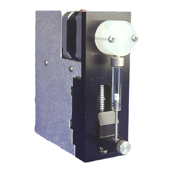
- Page 1 CAVRO XP 3000 Modular Digital Pump ’ PERATOR ANUAL 725730C , 1998 UGUST CAVRO CAVRO SCIENTIFIC INSTRUMENTS, INC. 2450 ZANKER ROAD, SAN JOSE, CA 95131 TELEPHONE: (408) 953-3100 • (800) 231-0711 • FAX: (408) 953-3107 MAIL CAVRO CAVRO Contents i...
- Page 2 Cavro warrants that instruments manufactured and sold by Cavro will be free from defects in materials and workmanship for a period of twelve (12) months from the date of shipment to customer. Cavro’s liability for the breach of the foregoing warranty is limited to the repair or replacement of the products found to be other than warranted.
-
Page 3: Table Of Contents
Valve and Valve Drive...................1-5 Printed Circuit Board..................1-5 Communication Interfaces ................1-6 Multi-Pump Configurations ................1-7 Valve Sensor....................1-7 Tips for Setting Up the XP 3000................1-7 Mating Connector Suppliers ................1-8 Power and Electrical Considerations ..............1-9 Choosing a Power Supply................1-9 Integrating a Power Supply................1-9 Switching Power Supplies ................1-10 2 HARDWARE SETUP ................ - Page 4 Set Commands (Velocity and Acceleration) ..........3-34 Report Commands..................3-39 XP 3000 Microstep-Enabled Firmware Commands ........3-41 Error Codes and Query Status ..............3-43 4 SETTING UP THE XP 3000 FOR YOUR APPLICATION...... 4-1 Glossary ......................4-1 Optimizing XP 3000 Performance...............4-3 Helpful Hints ......................4-8 5 MAINTENANCE ..................5-1 Daily Maintenance....................5-1...
- Page 5 Symbol Definitions ...................2 Move Calculations....................3 C ASCII CHART OF CODES FOR U.S. CHARACTERS ......1 D CHEMICAL RESISTANCE CHART............1 E XP 3000 PHYSICAL SPECIFICATIONS..........1 F CAN COMMUNICATION COMMANDS ........... 1 G COMMAND QUICK REFERENCE ............1 Control Commands ....................1 Initialization Commands for 3-Port Valve and T-Valve...........1...
- Page 6 Figure 1-1. XP 3000 Modular Digital Pump....................1-3 Figure 1-2. Syringe Components ......................1-4 Figure 1-3. 3-Port Valve Components...................... 1-5 Figure 1-4. XP 3000 Printed Circuit Board External Connectors .............. 1-6 Figure 2-1. DB-15 Connector Pins ......................2-3 Figure 2-2. Termination Jumpers ......................2-4 Figure 2-3.
-
Page 7: Getting Started
• Choosing a Power Supply Regulatory Considerations The XP 3000 is a general laboratory module. Since it is not a medical device, it is not subject to FDA regulatory approval. The XP 3000 uses UL-approved components wherever possible. Wherever possible, UL-approved components have been used in the design and manufacturing of the XP 3000. -
Page 8: Xp 3000 Features At-A-Glance
XP 3000 Features at-a-Glance The XP 3000 is a compact syringe pump that is designed for OEM precision liquid handling applications. It has the following standard features and functions: • Small and lightweight • Syringe sizes from 50 µL to 5 mL •... -
Page 9: Functional Description Of The Xp 3000
Functional Description of the XP 3000 The XP 3000 uses a stepper-motor driven syringe and valve design to aspirate and dispense measured quantities of liquid. Both the syringe and the valve are replaceable. Functional descriptions and illustrations of each major XP 3000 component are provided in the sections that follow. -
Page 10: Syringe And Syringe Drive
Syringe and Syringe Drive The syringe plunger is moved within the syringe barrel by a rack and pinion drive that incorporates a 1.8° stepper motor and quadrature encoder to detect lost steps. The syringe drive has a 30 mm travel length and resolution of 3000 steps (3000 or 24000 steps for microstep-enabled firmware). -
Page 11: Valve And Valve Drive
Figure 1-3 shows the components of a 3-port valve. Figure 1-3. 3-Port Valve Components The XP 3000 is available with the following valves: • Three-port valve. This valve has an input port, output port, and syringe port. The syringe port is a “common”... -
Page 12: Communication Interfaces
EPROM, see Chapter 2, “Hardware Setup.” Communication Interfaces Depending on the pump configuration, the XP 3000 can communicate singly or in a multi-pump configuration through an RS-232, RS-485, or CAN (Controller Area Network) interface. For RS-232 and RS-485, baud rates of 9600 and 38400 are supported. -
Page 13: Multi-Pump Configurations
Valve Sensor The XP 3000 sensor board includes a circuit that detects fluid leakage out the back of the valve. The valve is made of a Kel-F body and a Teflon plug which rotates inside the body. Over time, the plug wears, causing the valve to leak. The length of time before leakage occurs depends on the type of fluids used, duty cycle of the pump, and maintenance procedures. -
Page 14: Mating Connector Suppliers
Mating Connector Suppliers Cavro does not sell mating connectors beyond those found on its evaluation power supply. For customer convenience, a list of DB-15 mating connectors is provided below (Table 1-1). Table 1-1. DB-15 Mating Connectors Manufacturer Description Manufacturing Part... -
Page 15: Power And Electrical Considerations
AC line voltage. Integrating a Power Supply When a power supply is used to operate more than one XP 3000 or other device, it must provide the total average current for all devices. The power supply and filter capacitance together must satisfy the total peak input current for all devices. -
Page 16: Switching Power Supplies
500mA may not provide sufficient current when the XP 3000 motors are idle and all other devices are in a low current state. If the XP 3000 is the only load on the 24V supply, a switcher should have a minimum load specification of 50mA or less. -
Page 17: Hardware Setup
Options Power The XP 3000 requires a 24VDC power supply with a current rating of at least 1.5A, provided through a DB-15 connector. Cavro recommends using one power cable for every two pumps to provide noise immunity; i.e., power should not be daisy-chained to more than two pumps. -
Page 18: Cabling
Cabling A single cable supplies both power and communications to each XP 3000. (Power is described in the “Power” section in this chapter.) Set a unique address to identify each pump module. For more information, see “Address Switch Settings” in this chapter; see also Chapter 3, “Software Communication.”... -
Page 19: Communication Interfaces
RS-232 interface, or CAN (Controller Area Network) interface. The RS-232 interface automatically converts the protocol to RS-485 for the benefit of any other devices which may be connected to the XP 3000’s RS-485 communications bus (this constitutes a so called “multi-drop” device configuration). -
Page 20: Figure 2-2. Termination Jumpers
Figure 2-2 shows the termination jumpers on the printed circuit board. Figure 2-2. Termination Jumpers NOTE Pumps are shipped with the RS-485 termination jumper installed on JP2. Please remove the jumpers if they are not needed. When communicating with the pumps via RS-232, one pump in the chain must be configured for RS-232 communication. -
Page 21: Figure 2-3. Rs-232 Multi-Pump Cabling
RS-232 C ABLING Figure 2-3. RS-232 Multi-Pump Cabling Hardware Setup... -
Page 22: Figure 2-4. Rs-485 Multi-Pump Cabling
RS-485 C ABLING Figure 2-4. RS-485 Multi-Pump Cabling Hardware Setup... -
Page 23: Figure 2-5. Can Multi-Pump Cabling
CAN C ABLING Figure 2-5. CAN Multi-Pump Cabling Hardware Setup... -
Page 24: Printed Circuit Board Settings And Options
Printed Circuit Board Settings and Options Configuration Jumpers (JP1) for Standard Firmware Connector JP1 on the XP 3000 printed circuit board is used to configure different modes of operation (see Figure 2-6). Jumpers are added or removed to enable or disable the different modes. - Page 25 100K baud for CAN (for microstep-enabled firmware) JP1-4 installed 38400 baud 125K baud for CAN (for microstep-enabled firmware) NOTE The XP 3000 is shipped with spare jumper placed across the top of pin JP4. This can be used to change the default configuration settings. Hardware Setup...
-
Page 26: Figure 2-7. Jp4 Jumper Settings Per Mode
• JP4 (mode jumper) UMPER When pins 1 and 2 are jumpered, the XP 3000 is in standard running mode. In this mode, the pump accepts all commands. CAUTION! For microstep-enabled firmware, when pins 2 and 3 are jumpered, the XP 3000 is in factory set mode. - Page 27 EEPROM self-test enabled JP1-4, Baud Rate This jumper position is used to select the baud rate for the RS-232/RS-485 version of the XP 3000. There are two baud rates to select from: JP1-4 removed 9600 baud (default setting) (100K baud for CAN)
-
Page 28: Figure 2-8. Printed Circuit Board Settings For Microstep-Enabled Firmware
Figure 2-8 shows the printed circuit board settings for the microstep-enabled firmware. Figure 2-8. Printed Circuit Board Settings for Microstep-Enabled Firmware 2-12 Hardware Setup... -
Page 29: Address Switch Settings
Address Switch Settings The address switch (see Figure 2-9) is located on the lower left of the XP 3000’s back panel. It is used to give each XP 3000 in a multi-pump configuration a unique or specific address, allowing the user to direct commands to specific pumps. The address switch has sixteen positions (numbered 0 through F). -
Page 30: Self-Test
Self-Test The “F” address switch position is used to activate the XP 3000 self-test. Self-test causes the XP 3000 to initialize then cycle repeatedly through a series of plunger movements at fifteen different speeds. If an error condition occurs, the pump stops moving. Typically, the self-test activates the pump at 800 strokes/hour. -
Page 31: Xp 3000 Without Valve
NOTE When using a valveless pump, remove the additional jumper and set JP4 to pins 2 and 3. The XP 3000 without valve uses the same commands as the XP 3000 with valve with the exception of the initialize command, valve commands and valve overload error. For more information on the commands, see Chapter 3, “Software Communication.”... -
Page 32: Installing Components
These instructions apply to the 3-port valve, the 3-port distribution valve, and the T- valve. To install the XP 3000 valve, follow these steps: Place the pump upright on a table surface, with the front facing you. Verify that the offset tab on the encoder in the pump is correctly oriented (vertically with the tab to your right). - Page 33 Install the valve by inserting the slot in the valve coupling onto the tab of the encoder. The valve should be oriented with the tube fittings on top and the syringe fitting on the bottom. Gently push the valve in place, matching the locating pins on the valve fit the holes on the front of the pump.
-
Page 34: Installing A Syringe
Installing a Syringe To install a syringe, follow these steps: Loosen the plunger lock screw approximately three full turns. Lower the plunger drive by sending the command [A3000R]. If power is not applied, the plunger drive can be manually lowered by pushing down firmly on the plunger holder assembly. -
Page 35: Mounting The Xp 3000
Mounting the XP 3000 Numerous tapped M3 x 0.5 mounting holes provide flexibility in mounting the XP 3000; there are several mounting options: mounting from the bottom mounting from the top mounting from the sides Mounting requirements vary for pumps with different valves. For more information, see the specific valve outline drawings. -
Page 36: Figure 2-12. Xp 3000 Threaded Mount Holes
Figure 2-12. XP 3000 Threaded Mount Holes 2-20 Hardware Setup... -
Page 37: Software Communication
Addressed four devices at a time (quad device) Addresses all devices on the bus For example, an XP 3000 with address switch set to 0 is addressed as device “31h” in the RS-232 or RS-485 communication protocol, hardware address 1 is addressed as device “32h,”... - Page 38 NOTE When using the Pump:Link software to send commands to a device, use the ASCII address values in Table 3-2 Table 3-2. Address Switch Settings in Hex (ASCII) Switch Single Device Dual Device Quad Device All Devices Setting ASCII ASCII ASCII Address Value...
-
Page 39: Communication Protocols
For instructions on using a Microsoft Windows Terminal Emulator, see “Using DT Protocol with Microsoft Windows” in this chapter. NOTE Cavro recommends using the OEM protocol. It provides increased error checking, i.e., checksums and sequence numbers are used. -
Page 40: Oem Communication Protocol
OEM Communication Protocol OEM communication is a robust protocol that includes automatic recovery from transmission errors. Table 3- describes each setting within the OEM communication protocol. Table 3-3. OEM Protocol (JP1-2, Jumper IN) Parameter Setting Character Format Baud rate 9600 or 38400 (set using JP1-4) Data bits Parity None... - Page 41 Pump Address The pump address is a hexadecimal number specific for each pump. Sequence Number/Repeat Flag The sequence number is a single byte that conveys both a sequence number (legal values: 1 to 7) and a bit-flag indicating that the command block is being repeated due to a communications breakdown.
- Page 42 Scenario 2. The computer sends a command block stamped with sequence #1 to the pump. The pump never receives the command due to a communication error and thus does not send an acknowledgement to the PC. The PC waits 100 ms for the acknowledgement, then retransmits the command block with the sequence number left at 1 and the repeat bit set to indicate a retransmission.
- Page 43 Checksum The checksum is the last byte of the message string. All bytes (excluding line synchronization and checksums) are XORed to form an 8-bit checksum. This is appended as the last character of the block. The receiver compares the transmitted value to the computed value.
-
Page 44: Data Terminal (Dt) Protocol
Data Terminal (DT) Protocol The DT protocol can be used easily from any terminal or terminal emulator capable of generating ASCII characters at 9600 baud, 8 bits, and no parity. Table 3-4. DT Protocol (JP1-2, Jumper OUT) Character Format Parameter Setting Baud rate 9600 or 38400 (set using JP1-4) - Page 45 DT P ROTOCOL NSWER LOCK HARACTERS The answer block characters comprising the DT communication protocol are described below. Only unique answer block entries are listed in this section. For information on command and answer block commands (characters), see the previous section, “DT Protocol Command Block Characters.”...
-
Page 46: Using Dt Protocol With Microsoft Windows
Power on the pump. Type /1ZR<CR> to initialize the pump. To run the pump, see the commands listed in “Using the XP 3000 Command Set” in this chapter. To communicate with the XP 3000 using Windows 95/NT, follow these steps: To connect the XP 3000 to a communication ports on the PC, first select the Start menu and choose Run. - Page 47 The communication protocol is detected automatically. Power on the pump and initialize it by typing /1ZR and pressing Enter. To run the pump, see the commands listed in “Using the XP 3000 Command Set” in this chapter. 3-11...
-
Page 48: Can Interface Communications
“1” means the message is from the slave to the master. Group This is the group number (0 - 7). Each type device on the XP 3000 CAN has a group assignment. The XP 3000 is assigned to group 2. The group number “1” is reserved for the boot request procedure. - Page 49 Frames This lets the device know what type message is coming. See “CAN Frame Types.” This bit is not used in Cavro’s CAN implementation and should always be set to 0. Length This is the length of the data block in the message. Data blocks can be from zero to eight bytes in length.
- Page 50 Command Description Reset mode. This resets the pump and begins the boot request procedure. Start loaded command. Just like sending an [R] command after a string has been loaded. Clear loaded command. This clears out the command buffer. Repeat last command. This command does the same thing as the [X] command.
- Page 51 RS-232 or RS-485. For command strings that are more than eight bytes in length, multi- frame messages are used. This permits long program strings to be sent as with the other communications interfaces (remember that the XP 3000 buffer size is 256 characters). 3-15...
- Page 52 ANDLING OF EQUESTS When the pump is first powered up or receives a system reset command (frame type, command 0), the pump notifies the host of this condition by sending a boot request message at 10 to 12 second intervals until it receives a proper response. The group number is 1 for the boot request message.
- Page 53 Example 2. The pump is set to address 6 Pump sends: Group Device Frame Length 0110 0000 Host acknowledges: Group Device Frame Length Node ID Slave ID 0000 0010 0010 0110 0010 0110 Host acknowledges the boot request with: Dir = 0 Host to slave Note: Boot MID is the same for all nodes...
- Page 54 NOTE Only one command of a given frame type can be in progress at any one time; e.g., after issuing a command to a slave pump with frame type = 1, the master must wait for the answer with frame type = 1 before issuing the next command with frame type = 1.
- Page 55 Multi-Frame Command The host commands [Z2S5IA3000OgHD300G10G5R] to a pump, and the pump is set to address 0. Host sends: 0000 1000 Z2S51A30 Group Device Frame Data bytes type 0000 1000 00OgHD30 Group Device Frame Data bytes type 0000 0111 0G10G5R Group Device Frame...
- Page 56 Query Command The host commands 29 of frame type 6 to a pump, and the pump is set to address 1. Host sends: 0001 0010 Group Device Frame Data bytes type Pump reports: 0001 0010 <60h><00h> Group Device Frame Data bytes type NOTE For query commands, no acknowledge frame is needed.
-
Page 57: Using The Xp 3000 Command Set
Using the XP 3000 Command Set The XP 3000 features a robust command set which allows a wide range of parameters to be defined by the user. Many of the commands have default values; however, the default values may not provide the optimal settings for your application. Take a moment to familiarize yourself with each command in order to obtain the best performance for your application. - Page 58 It is important to send the velocity commands in the proper order to insure that all parameters are read. The XP 3000 queries for the input of the velocity commands in the following order: backlash [K], slope [L], start velocity [v], top velocity [V], and cutoff velocity [c].
-
Page 59: Control Commands
Control Commands XECUTE OMMAND OR ROGRAM TRING The [R] command tells the pump to execute a previously sent command or program string. Commands containing an [R] at the end of the string will execute immediately. If the command or program string is sent without the [R], it is placed in the command buffer. Sending the [R] alone will execute the last unexecuted command in the buffer. - Page 60 Table 3-5. Example Program String Command Description Segment Move plunger to position 0. Outer loop start. Move plunger down 50 steps. Inner loop start. P100 Move plunger down 100 steps. D100 Move plunger up 100 steps. Inner loop, repeat 10 times. Outer loop, repeat five times.
- Page 61 The syntax for this command is: [J<n>], where <n> = 0..7 (0 is the default) The XP 3000 provides three TTL outputs on JP3 (pins 13, 14, and 15) that correspond to outputs 1, 2, and 3. They are controlled as follows:...
- Page 62 ROGRAM TRING INTO The EEPROM is non-volatile memory within the XP 3000. Once a program string is stored in the EEPROM it provides the user with the option of computer-free operation. The [s] command is placed at the beginning of a program string to load the string into the EEPROM.
-
Page 63: Initialization Commands
[e<n>], where<n> = 0..14 (the string number) Linking Program Strings in the EEPROM EEPROM program strings can be linked by ending one program string with an [e] command that refers to a second program string. Example Program Strings: [slZIA3000OA0G5e2R] [s2gIA3000OgHD300G10GR] The first string loads an initialization and prime sequence into program 1 of the EEPROM (address switch position 1). - Page 64 Table 3-6. Recommended Initialization Forces by Syringe Parameter Force Syringes 0, 3-40 Full 1.0 mL and larger Half 50, 100, 250, 500 µL Z = Z0 2) 2 - 9 are reserved 3) Z10-Z40 (or Y10-Y40) are initialization speeds which correspond to ([S] commands, Set Speeds) S10-S40 found in “Set Commands (Velocity and Acceleration)”...
-
Page 65: Plunger Movement Commands
CAUTION! Once the [W] command is issued to a pump with a valve mounted, the valve will not move until the power is cycled to the pump. z Set Counter Position (3-Port Distribution Valve Only) The [z] command sets the pump’s position counter to the value contained in the current encoder position. - Page 66 p <n> R ELATIVE ICKUP This is the same as the [P] command, except that the status bit of the reply string indicates that the pump is not busy. This is useful for on-the-fly speed changes. D <n> R ELATIVE ISPENSE The [D] command moves the plunger upward the number of steps commanded.
-
Page 67: Valve Commands
ALVE TO NPUT OSITION The [I] command moves the valve on the XP 3000 to the input position set by the [Y] and [Z] commands. For example: If the [I] command is sent after the [Z] command, the valve will be open on the left side (as viewed from the front of the pump). -
Page 68: Figure 3-1. Valve Positions For All Valve Types
Sending a Plunger Movement command causes an error 11 (plunger move not allowed). (3-P ALVE TO XTRA OSITION ISTRIBUTION ALVE The [E] command moves the valve on the XP 3000 to the extra position (port) relative to the [Y] and [Z] commands. 3-32 Software Communication... -
Page 69: Valve Leakage Detection Commands
Valve Leakage Detection Commands ^<n> S HRESHOLD ALUE FOR LUID ETECTION The [^] command is used to set a fluid detection value that best suits the application and fluids used. The syntax is: [^<n>], where <n> = 0..255 The higher the value, the more sensitive the detector. A setting of 150 detects water leakage. -
Page 70: Set Commands (Velocity And Acceleration)
Set Commands (Velocity and Acceleration) Set commands are used to control the speed of the plunger. Plunger movement is structured into three phases: Ramping Up. Plunger movement begins with the start velocity and accelerates with the programmed slope to the constant or top speed. Constant or Top Speed. - Page 71 Changing Speed on the Fly Speed changes can be made while the syringe plunger is moving. This is called “changing speed on the fly.” Speeds can be decreased or increased between 5 and 1024 Hz (i.e., in the microstepping region). To change speed on the fly: Issue speed commands with identical start and top velocities (e.g., [v100V100]), followed by a lowercase Plunger Move command.
- Page 72 L <n> S LOPE During the beginning and end of a move, the plunger ramps up and down to top speed. The ramp is programmed using the Slope command. It is calculated as <n> x 2.5 kHz/sec. The syntax for this command is: [L<n>], where <n>...
- Page 73 These speeds do not cover the full range of speeds the plunger can travel. They are commonly used velocities provided for the convenience of the user. All times are approximate and will vary with different ramp speeds and cutoffs. Cavro also provides a utility for performing theoretical speed calculations in Pump:Link Evaluation Software (in the Utility menu on the user interface).
- Page 74 Speed codes, the Hz (half-steps/second) equivalent, and seconds per stroke are listed below. Seconds/stroke values are based on default ramping. Speed Code Pump Freq (Hz) Seconds/Stroke 5600 5000 4400 3800 3200 2600 2200 2000 1800 1600 1400 1200 1000 10.0 15.0 30.0 31.0...
-
Page 75: Report Commands
NOTE To achieve maximum stroke time (20 minutes or 1200 seconds), you must use the [V5] command. c <n> C UTOFF ELOCITY IN The [c] command sets the velocity at which the plunger ends its movement. The plunger will ramp down (slope) from the peak velocity. The [c] command overwrites the [C] command. - Page 76 EPORT BSOLUTE LUNGER OSITION The [?] command reports the absolute position of the plunger in steps [0..3000], [0..24000 in microstep mode]. ?1 R EPORT TART ELOCITY The [?1] command reports the start velocity in kHz/sec [50..1000]. ?2 R EPORT ELOCITY The [?2] command reports the set top velocity in kHz/sec [5..5800].
-
Page 77: Xp 3000 Microstep-Enabled Firmware Commands
[N<n>], where <n> = 0 or 1 When <n> = 0, the microstep mode is off and the XP 3000 uses the standard 3000 increments/full stroke. If <n> = 1, microstep mode is on and the XP 3000 uses 24,000 increments/full stroke. - Page 78 k <n> S YRINGE OLUME OMMAND The [k] command allows the setting of the number of steps that the plunger travels after initialization. This is to minimize deal volume. The syntax for this command is: [k<n>], where <n> = the offset in steps from zero position <n>...
-
Page 79: Error Codes And Query Status
RROR ODES Error codes describe problem conditions that may be detected in the XP 3000 (excluding error code 0). Error codes are returned in the least significant four bits of the status byte. If an error occurs, the pump stops executing commands, clears the command buffer, and inserts the error code into the status byte. - Page 80 Reinitialize the pump. 6 (06h) EEPROM Failure. This error occurs when the EEPROM is faulty. If you receive this error, please call Cavro Technical Service. 7 (07h) Device Not Initialized. This error occurs when the pump is not initialized. To clear the error, initialize the pump.
- Page 81 The pump handles errors differently, depending on the error type. There are four error types, which are described below. Immediate Errors. These include “Invalid Command” (error 2), “Invalid Operand” (error 3), “Invalid Command Sequence” (error 4), and “Plunger Move Not Allowed” (error 11).
- Page 82 Table 3-8. Error Codes and ASCII and Hexadecimal Values Status Byte Hex # if Dec # if Error Bit 5 = Bit 5 = Code 7 6 5 4 3 2 1 0 or 1 or 1 Number Error 0 1 X 0 0 0 0 0 No Error 0 1 X 0 0 0 0 1 Initialization...
-
Page 83: Glossary
[syringe size, tubing inner diameter (I.D.), and valve I.D.] determines the behavior of the XP 3000 in a particular application. Following is a description of the hardware, fluid, and pump control parameters to be evaluated and optimized in managing these interdependencies for optimal pump performance. -
Page 84: Figure 4-1. Syringe Speed
carryover Contamination of a volume of fluid by residual fluid from a previous aspiration or dispense. Carryover causes variability in final volume and concentration. cavitation Formation of air bubbles due to rapid pressure changes. dilution effect Reduction in sample or reagent concentration, caused by contact with system fluid or residual fluid from a previous aspiration or dispense. -
Page 85: Optimizing Xp 3000 Performance
# of steps = (pump resolution) x volume (syringe size) For example, to aspirate 100 µ L using an XP 3000 pump with 1 mL syringe, move the plunger as follows: = 3000 steps x 100 µ L = 300 steps # of steps 1 mL x 1000 µ... - Page 86 In tubing selection, the general rule is that smaller syringes work best with smaller I.D. tubing and larger syringes with larger I.D. tubing. Most XP 3000 valve styles have an internal I.D. of 0.059" (approx. 1/16"). For aspirate/dispense tubing a thermal-drawn tip or tapered tip is most common, providing good breakoff and excellent accuracy and precision for most applications.
- Page 87 Check communications to the pump. a) Open the Pump:Link program to the XP 3000 menu (full page), or use your own communications program. b) Send the command [&] to read the pump’s firmware revision number.
- Page 88 Set start velocity and top velocity. The XP 3000 plunger speed can be controlled from 1.2 seconds per stroke to 20 minutes per stroke (top speed) using the [S] command. (The [V] command allows a slightly larger speed range.) As a general rule, aspiration should be slow (to avoid...
- Page 89 Set backlash compensation. The XP 3000 pump control includes backlash compensation during aspiration. The backlash compensation causes the plunger to move down to the calculated stopping point, then down an additional set number of steps. On reversing direction, the plunger moves back up the same number of steps.
-
Page 90: Helpful Hints
Helpful Hints To maintain pump performance, keep the following in mind when operating the XP 3000: Wipe up all spills immediately. Pumping cold fluids may cause leaks, the result of differing coefficients of expansion of Teflon and glass. Leaks may occur when pumping fluids that are at or below 15 °... -
Page 91: Maintenance
Do not allow the pump(s) to run dry for more than a few cycles. Weekly Maintenance The fluid path of the XP 3000 must be cleaned weekly to remove precipitates such as salts, eliminate bacterial growth, and so on. Any of the three following cleaning procedures can be used: •... -
Page 92: Weak Detergent Cleaning
Weak Detergent Cleaning To clean the pump with weak detergent, follow these steps: Prime the pump with a weak detergent solution (e.g., 2% solution of CONTRAD®, RoboScrub, or flo-kleen) and allow the solution to remain in the pump with the syringe fully lowered for 30 minutes. -
Page 93: 10% Bleach Cleaning
The frequency of replacement will depend on the duty cycle, fluids used, and instrument maintenance. Quality Control Assurance Check the accuracy and precision of the XP 3000 on a regular basis. Cavro recommends checking both accuracy and precision gravimetrically, using an analytical balance with the capability to measure to 0.1 mg. Gravimetric measurements should be corrected for the specific gravity of water at the ambient temperature. -
Page 94: Replacing Dispense Or Reagent Tubing
reading caused by fluid adhering to the tip of the aspirate tubing, a small amount of surfactant should be added to the water (e.g., Fluorad â at a 0.01% concentration). % Coefficient of Variation = (Standard Deviation/Mean) * 100 æ ö... -
Page 95: Replacing A Syringe
Replacing a Syringe To replace a syringe, follow these steps: Remove the liquid from the syringe. Loosen the plunger lock screw approximately three full turns. Lower the plunger drive by sending the [A3000R] command. If power is not applied, the plunger drive can be manually lowered by firmly pushing down on the plunger holder assembly. -
Page 96: Replacing The Reagent Syringe Seals
Replacing the Reagent Syringe Seals NOTE See Chapter 2, “Hardware Setup,” for an illustration of the syringe components. To replace the reagent syringe seals, follow these steps: Remove the syringe from the pump. Remove the syringe plunger from the barrel. Using a single edged razor or precision knife, carefully slice the old seal lengthwise and remove it from the plunger. -
Page 97: Replacing The Xp 3000 Valve
Replacing the XP 3000 Valve To replace the XP 3000 valve, follow these steps: Remove the fluid from the pump. Initialize the pump using the [ZR] command so that the offset tab on the encoder is in the correct orientation (vertically and to your right). -
Page 98: On-Site Replacements
On-Site Replacements Replacing the Printed Circuit Board (PCB) To replace the printed circuit board, follow these steps: Power off the pump. Remove the back panel by unscrewing the four hex side panel screws and the two standoff screws holding the DB-15 connector. Remove the two hex screws that hold the printed circuit board to the pump. -
Page 99: Technical Service
6 - Technical Service For information or questions regarding ordering or operating the XP 3000, please contact Cavro Technical Service using one of the methods listed below. By phone 408-953-3100 or 800-231-0711 By fax 408-953-3107 By e-mail cavro@cavro.com Our mailing address is: Cavro Scientific Instruments, Inc. -
Page 100: A Ordering Information
A - Ordering Information This appendix is a summary of available XP 3000 configurations, other Cavro liquid handling components, and spare parts for the XP 3000. Available Configurations The available configurations and their respective part numbers for both standard firmware and microstep-enabled firmware are listed below. -
Page 101: Xp 3000 Spare Parts
XP 3000 with 90º 3-port distribution valve, 726349 RS-232/RS-485 1/4-28" fittings XP 3000, T-90, 1/4-28" fittings 728878 RS-232/RS-485 NOTE This table is provided for customers who are not using Cavro’s microstep- enabled firmware. XP 3000 Spare Parts The following spare parts are available: • • Syringes Printed Circuit Board •... -
Page 102: Syringes
Syringes Table A-3. Syringes Part Number Description 725676 Syringe, 50 µL 725682 Syringe, 100 µL 725589 Syringe, 250 µL 725590 Syringe, 500 µL 725591 Syringe, 1.0 mL 725592 Syringe, 2.5 mL 725593 Syringe, 5.0 mL Syringe Seals Table A-4. Seals Part Number Description 3225... -
Page 103: Valves
Valves Table A-6. Valves Part Number Description 725587 Valve, 3-Port (1/4-28" fitting) 725588 Valve, 3-Port (M6 fitting) 725727 “Y” Block (1/4-28" fitting) 725729 “Y” Block (M6 fitting) 726273 T-valve (1/4-28" fitting) 726346 3-port distribution (1/4-28" fitting) Printed Circuit Board Table A-7. Printed Circuit Board Part Number Description 725688... -
Page 104: Interconnect Tubing
Interconnect Tubing Table A-8. Interconnect Tubing Part Description Material Length Units Tube Ends Number (Inches) 1067 Reagent tube 60" .063 1/4-28" to blunt cut 4333 Aspirate/Dispense tube 30" .053 Necked 4410 Aspirate/Dispense tube 40" .031 Thermal drawn 4609 Reagent tube 12"... -
Page 105: Pump Evaluation Accessories
Description 1590 Fitting, Tube, 0.076 ID, (2/pk) 1589 Fitting, Tube, 0.138 ID, (2/pk) 724757 Wrench, 5/16" and 9/64" 725730 Manual, Operator's, XP 3000 725731 Packaging 725772 Connector, XP mating 973309 Fitting, Tube, 0.085 ID, M6 973308 Fitting, Tube, 0.100 ID, M6 973307 Fitting, Tube, 0.125 ID, M6... -
Page 106: Other Cavro Products
MSP 9000/9500 Mini Sample Processors One- or two-arm robotic benchtop workstations designed for automating sample preparation or assay methods. Cavro’s modular component technology allows both flexibility and quick customization. A variety of liquid-handling modules and a choice of standard cap-piercing, disposable tip, or multi-channel probes are available. All instruments include liquid-level sensing and step-loss detection. -
Page 107: Xl Series Smart Valve
XL Series Smart Valve A compact, stepper motor driven module for OEM liquid handling applications, the Smart Valve is available with 3-, 4-, or 6-port valves. It uses the same communication characteristics as the XL 3000 Modular Digital Pump: RS-232 or RS-485 interfaces and a choice of two communication protocols. -
Page 108: Smart I/O Board
I/O ports from an external serial line. The board can be controlled by RS-232 or RS-485. It can also be placed on an RS-485 bus with other Cavro pumps and smart devices. The I/O signal is CMOS (0-5 volts). I/O lines include 16 inputs, 16 outputs, and four analog inputs. -
Page 109: B Plunger Information
B - Plunger Information Plunger Force Figure B-1 shows a typical XP 3000 force curve for reference use only. Forces were determined by hanging weights from the plunger pin and pulling them up at various speeds. The plunger speed in Hz is shown on the X axis of the graph; plunger force is shown on the Y axis. -
Page 110: Plunger Time Calculations
Plunger Time Calculations Following are calculations for determining XP 3000 plunger speeds. Four different cases are presented below. Start, top, and cutoff velocities are equal, or top velocity is less than 50 Hz. Typical move with ramp up, constant speed and ramp down. -
Page 111: Move Calculations
Move Calculations 1. S TART UTOFF ELOCITIES ARE QUAL OR ELOCITY IS SMALLER 50 H THAN Case 1 is used when v = V = c or v = <50 Diagram of move: Speed [Hz] V=c=v time in s Calculation: v = 900 Hz L = 14 V = 900 Hz A = 3000 full steps c = 900 Hz... - Page 112 Speed [Hz] time in s Calculation: v = 50 Hz L = 14 V = 5800 Hz A = 3000 full steps c = 500 Hz Ramp Up Steps − − 5800 half steps ∗ ∗ 2 14 2500 Ramp Down Steps −...
- Page 113 Constant Speed Time 5042 seconds 5800 Total Move Time 16 87 15 1 18 seconds Plunger Information...
- Page 114 3. M OVE TOO MALL TO EACH UTOFF ELOCITY Case 3 is used when Vn < c Diagram of Move: Speed [Hz] time in s Calculation: v = 50 Hz L = 14 V = 5800 Hz A = 5 full steps c = 900 Hz Theoretical Top Velocity ∗...
- Page 115 4. M OVE TOO MALL TO EACH ELOCITY Case 4 is used when Vn < V and Vn > c Diagram of Move: Speed [Hz] time in s Calculation: v = 50 Hz L = 14 V = 5800 Hz A = 350 full steps c = 900 Hz Top Velocity...
-
Page 116: C Ascii Chart Of Codes For U.s. Characters
C - ASCII Chart of Codes for U.S. Characters Table C-1. ASCII Chart of Codes for U.S. Characters Decimal Hexadecimal Character or Decimal Hexadecimal Character or Function Function none \ (backslash) ^ (control) — (emdash) ` (tick) " & ASCII Chart of Codes for U. S. Characters... - Page 117 Decimal Hexadecimal Character or Decimal Hexadecimal Character or Function Function ' (apostrophe) , (comma) - (en dash) . (period) (left brace) (vertical bar) < (right brace) ~ (tilde) > ASCII Chart of Codes for U. S. Characters...
-
Page 118: D Chemical Resistance Chart
CAUTION! Failure to test chemicals used in individual applications with the XP 3000 may result in damage to the pump and/or test results. The materials listed in Table D-1 are used in the following areas of the XP 3000: Telfon® (PTFE, TFE, FEP) Tubing, Valve Plug, Seal Kel F®... - Page 119 Minor effect – good Moderate effect – fair Severe effect - not recommended Polypropylene - Satisfactory to 22° C (72° F) Polypropylene - Satisfactory to 49° C (120° F) Table D-1. Plastic Materials Used in Cavro Pumps Solvent Teflon Kel F Polypropylene...
- Page 120 Solvent Teflon Kel F Polypropylene Formic Acid Freon Gasoline Glycerin Hydrochloric Acid Hydrochloric Acid (conc) Hydrofluoric Acid Hydrogen Peroxide Hydrogen Peroxide (conc) Hydrogen Sulfide Kerosene Methyl Ethyl Ketone (MEK) Methyl Alcohol Methylene Chloride Naptha Nitric Acid Nitric Acid Nitrobenzene Phenol Pyridine Silver Nitrate Soap Solutions...
-
Page 121: E Xp 3000 Physical Specifications
E - XP 3000 Physical Specifications Table E-1. XP 3000 Physical Specifications Height 5.0 in (127 mm) Dimensions Width 1.8 in (45.7 mm) Depth 4.5 in (114.3 mm) from front panel to connector Weight 2.5 lbs (1.1 kg) Resolution 3000 steps (24000-step capability when using microstep-enabled... - Page 122 Two TTL level inputs with 4.7k pull ups Inputs Outputs Three outputs, CMOS (HC) level Environmental Operating Temperature 59°F (15°C) to 104°F (40°C) (mechanism) Operating Humidity 20-95% RH at 104°F (40°C) (mechanism) Storage Temperature -4°F (20°C) to 149°F (65°C) XP 3000 Physical Specifications...
-
Page 123: F Can Communication Commands
F - CAN Communication Commands Command Type Command Valid/Invalid CAN Equivalent Initialization Z, Y Valid None Initialization Valid None Plunger Movement A, a, P, p, D, d Valid None Valve I, O, B Valid None Valve E, ^ Valid None S, V, v, C, c, L, K Valid None... -
Page 124: G Command Quick Reference
G - Command Quick Reference Control Commands Command Value Description Executes command or command string Repeats last command string G <n> <n> = 0..30000 Repeats command sequence Marks start of a repeat sequence M <n> <n> = 5..30000 Delay in milliseconds H <n>... -
Page 125: Plunger Movement Commands/Status Bit Reports
Plunger Movement Commands/Status Bit Reports Command Value Description Status A <n> <n> = 0..3000 [A]bsolute Position Busy a <n> <n> = 0..3000 [a]bsolute Position Ready P <n> <n> = 0..3000 Relative [P]ickup Busy p <n> <n> = 0..3000 Relative [p]ickup Ready D <n>... -
Page 126: Microstep-Enabled Firmware Commands
Microstep-Enabled Firmware Commands Command Value Description <n> = 0 or 1 Sets the microstep mode off or on. <n> = 0..40 Sets speed <n> = 5..6000 Sets end velocity in HS/s <n> = 50..1000 Sets start velocity in HS/s <n> = 50..2700 Sets cutoff velocity in HS/s <n>... -
Page 127: Error Codes And Status Byte
Error Codes and Status Byte Status Byte Hex # if Dec # if Error Bit 5 = Bit 5 = Code 7 6 5 4 3 2 1 0 or 1 or 1 Number Error 0 1 X 0 0 0 0 0 No error 0 1 X 0 0 0 0 1 Initialization... - Page 128 · 4-2 I (Move Valve to Input Position) · 3-31 cavitation · 4-2 Initialization · 3-27, G-1 Cavro Mini Wash (MW) · A-9 Initialization for 3-port distribution valve · G-1 chemical compatibility Initialization, 3-port and T-valve · 3-28 checking · 4-3 J (auxiliary outputs) ·...
- Page 129 K (Backlash Steps) · 3-34 mating connectors · 1-9 k (Syringe Dead Volume) · 3-42 pin assignments · G-4 L (Set Slope) · 3-36 DB-15 connector pin positions · 2-3 M (Delay Command Execution) · 3-24 dilution effect · 4-2 microstep-enabled firmware ·...
- Page 130 dispense or reagent tubing replacing · 5-4 DT protocol · 3-3, 3-8 maintenance answer block characters · 3-9 10% bleach cleaning · 5-3 command block characters · 3-8 daily · 5-1 using with Windows 3.x · 3-10 periodic · 5-3 using with Windows 95 ·...
- Page 131 precision printed circuit board · 1-7 determining · 5-4 components · 2-12 priming · 4-2 configuration jumpers · 2-8 replacing · 5-8 termination jumpers · 2-4 printed circuit board components · 1-7 pump initializing · 4-5 pump boot requests · 3-16 pump busy/not busy status bit ·...
- Page 132 XL 3000 Series Multi-Channel Pumps · A-8 XL Series Smart Peristaltic Pump · A-8 XL Series Smart Valve · A-8 XP 3000 · See also address switch, commands, communication interfaces, EPROM, jumpers, microstep-enabled firmware, multi-pump configurations, power supply, printed circuit board, syringe, syringe drive, valve accessories ·...
- Page 133 "o"-ring part numbers · A-3 syringe part numbers · A-3 syringe seal part numbers · A-3 unpacking · 1-3 valve part numbers · A-4 valve types · 3-21 XP 3000 performance optimizing · 4-3, 4-8 XP 3000 without valve · 2-15 Index 1...
Need help?
Do you have a question about the XP 3000 and is the answer not in the manual?
Questions and answers