Table of Contents
Advertisement
Advertisement
Table of Contents

Related Manuals for Stairville Power Strobe 1500 DMX


Summary of Contents for Stairville Power Strobe 1500 DMX
- Page 1 Power Strobe 1500 DMX stroboscope user manual...
- Page 2 Musikhaus Thomann Thomann GmbH Hans-Thomann-Straße 1 96138 Burgebrach Germany Telephone: +49 (0) 9546 9223-0 E-mail: info@thomann.de Internet: www.thomann.de 22.02.2016, ID: 168875...
-
Page 3: Table Of Contents
1.2 Notational conventions........................7 1.3 Symbols and signal words....................... 7 Safety instructions..........................10 Features............................... 15 Installation..............................16 Starting up..............................20 Connections and controls........................22 Operating..............................26 Maintenance.............................. 29 Technical specifications........................36 Plug and connection assignments....................37 Troubleshooting............................38 Power Strobe 1500 DMX... - Page 4 Table of contents Cleaning............................... 40 Protecting the environment......................41 stroboscope...
-
Page 5: General Information
If you sell the unit please make sure that the buyer also receives this manual. Our products are subject to a process of continuous development. Thus, they are subject to change. Power Strobe 1500 DMX... -
Page 6: Further Information
General information 1.1 Further information On our website (www.thomann.de) you will find lots of further information and details on the following points: Download This manual is also available as PDF file for you to download. Use the search function in the electronic version to find the topics of Keyword search interest for you quickly. -
Page 7: Notational Conventions
The letterings for connectors and controls are marked by square brackets and italics. Examples: [VOLUME] control, [Mono] button. 1.3 Symbols and signal words In this section you will find an overview of the meaning of symbols and signal words that are used in this manual. Power Strobe 1500 DMX... - Page 8 General information Signal word Meaning DANGER! This combination of symbol and signal word indicates an immediate dangerous situation that will result in death or serious injury if it is not avoided. WARNING! This combination of symbol and signal word indicates a pos‐ sible dangerous situation that can result in death or serious injury if it is not avoided.
- Page 9 General information Warning signs Type of danger Warning – hot surface. Warning – dangerous optical radiation. Warning – suspended load. Warning – toxic substances. Warning – danger zone. Power Strobe 1500 DMX...
-
Page 10: Safety Instructions
Safety instructions Safety instructions Intended use This device is intended to be used as an illumination effect. The device is designed for profes‐ sional use and is not suitable for use in households. Use the device only as described in this user manual. - Page 11 Never let children unattended use electrical devices. DANGER! Electric shock caused by high voltages inside Within the device there are areas where high voltages may be present. Never remove any covers. There are no user-serviceable parts inside. Power Strobe 1500 DMX...
- Page 12 Safety instructions DANGER! Electric shock caused by short-circuit Do not modify the mains cable or the plug. Failure to do so could result in electric shock/death or fire. If in doubt, seek advice from a registered electrician. WARNING! Eye damage caused by high light intensity Never look directly into the light source.
- Page 13 Keep the device away from naked flames. NOTICE! Operating conditions This device has been designed for indoor use only. To prevent damage, never expose the device to any liquid or moisture. Avoid direct sunlight, heavy dirt, and strong vibrations. Power Strobe 1500 DMX...
- Page 14 Safety instructions NOTICE! Power supply Before connecting the device, ensure that the input voltage (AC outlet) matches the voltage rating of the device and that the AC outlet is protected by a residual current circuit breaker. Failure to do so could result in damage to the device and possibly injure the user.
-
Page 15: Features
Stroboscope effect flash light energy: 1500 W strobe frequency steplessly adjustable brightness steplessly adjustable control via DMX or optional remote Operating modes: Master/Slave, DMX DMX address and operating mode adjustable via DIP switches illuminant included Power Strobe 1500 DMX... -
Page 16: Installation
Installation Installation Unpack and carefully check that there is no transportation damage before using the unit. Keep the equipment packaging. To fully protect the device against vibration, dust and moisture during transportation or storage use the original packaging or your own packaging material suitable for transport or storage, respectively. - Page 17 When mounting the device onto a stand, ensure that the stand is in a safe and stable position and that the weight of the device does not exceed the maximum permissible load capacity of the stand. Power Strobe 1500 DMX...
- Page 18 Installation NOTICE! Possible data transmission errors For error-free operation make use of dedicated DMX cables and do not use ordi‐ nary microphone cables. Never connect the DMX input or output to audio devices such as mixers or ampli‐ fiers. Mounting options You can install the unit in hanging or standing position.
- Page 19 Installation Please note that this device must not be connected to a dimmer. Power Strobe 1500 DMX...
-
Page 20: Starting Up
Starting up Starting up Establish all connections as long as the unit is switched off. Use the shortest possible high- quality cables for all connections. stroboscope... - Page 21 Connect the output of the first DMX device to the input of the second one, and so on to form a daisy chain. Always ensure that the output of the last DMX device in the daisy chain is terminated with a resistor (110 Ω, ¼ W). Power Strobe 1500 DMX...
-
Page 22: Connections And Controls
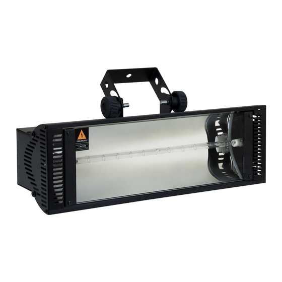
Connections and controls Connections and controls Front panel stroboscope... - Page 23 Connections and controls 1 Illuminant. 2 Mounting bracket. 3 Locking screws for the mounting bracket. 4 Knurled screw to open the front cover. Power Strobe 1500 DMX...
- Page 24 Connections and controls Control panel and connections stroboscope...
- Page 25 7 [DMX IN] DMX input. 8 [DMX OUT] DMX output. 9 [ONLY FOR REMOTE CONTROL] 1/4" phone socket to connect an optionally available remote control. 10 [START ADDRESS SELECT] DIP switch for setting the DMX address. Power Strobe 1500 DMX...
-
Page 26: Operating
Operating Operating Starting the device To start up the device, connect it to the mains. The device is immediately ready for operation. Operating mode ‘Master / Salve’ This setting is only relevant if the device is working as Slave in a Master / Slave configuration and is not controlled via DMX. - Page 27 Operating mode ‘DMX’ This setting is only relevant when the device is controlled via DMX. Use the DIP switches of the device to set the desired DMX address between 1 and 512 (see the following figure). Power Strobe 1500 DMX...
- Page 28 Operating DMX channel allocation Channel Value Function Strobe frequency 0 … 15 not lit 16 … 255 Level 1 (1 flash per second) … level 15 (12 flashes per second) Brightness 0 … 15 Blackout 16 … 255 Level 1 … level 15 Resettable 15 A fuse.
-
Page 29: Maintenance
Risk of burns at the surface and inside of the device The surface and the inner parts of the device can become very hot during opera‐ tion. After switching off the device wait for at least 15 minutes before you start any maintenance activities. Power Strobe 1500 DMX... - Page 30 Maintenance WARNING! Danger of burns in case of inappropriate handling of the illuminant The light source used in this device is under high pressure, especially when heated, and can explode if handled inappropriately. Allow the illuminant to cool down for at least two hours before starting any main‐ tenance or replacement.
- Page 31 To remove the remnants of broken discharge lamps wear Nitrile protective gloves, breathing and mouth protection. Dispose of broken or worn discharge lamps as hazardous waste according to legal regulations in a tightly closed container. Power Strobe 1500 DMX...
- Page 32 Maintenance WARNING! Danger of burns and eye injuries caused by high light intensity The light source used in this device produces visible and invisible light beams of high intensity. Never look directly into the light source. Do not use the device when covers, shieldings, lenses or other optical compo‐ nents are missing or damaged.
- Page 33 Only use a lamp of the specified type. Notes on the illuminant The device must only be operated with an illuminant type xenon 1500. Observe the safety instructions of the illuminant manufacturer. Power Strobe 1500 DMX...
- Page 34 Maintenance Procedure Make sure that the device is turned off, disconnected from the mains and completely cooled down. Place the device on a clean, flat work surface. Unscrew the two knurled screws (A) right and left on the housing completely and open up the front cover forward.
- Page 35 Pull the retaining springs (B) as far back that you can remove the illuminant. Installation of the new illuminant is done in reverse order. Only reconnect the device to the power grid after the front cover has been closed and securely fixed with the two knurled screws. Power Strobe 1500 DMX...
-
Page 36: Technical Specifications
Technical specifications Technical specifications Number of DMX channels Strobe frequency steplessly adjustable from 1 … 12 flashes per second Brightness steplessly adjustable from 0 … 100 % Power consumption approx. 1600 W Operating supply voltage AC 230 V 50 Hz Fuse resettable, 15 A Dimensions (W ×... -
Page 37: Plug And Connection Assignments
The unit offers a 3-pin XLR socket for DMX output and a 3-pin XLR plug for DMX input. Please refer to the drawing and table below for the pin assignment of a suitable XLR plug. Configuration Ground, shielding Signal inverted (DMX–, ‘cold signal’) Signal (DMX+, ‘hot signal’) Power Strobe 1500 DMX... -
Page 38: Troubleshooting
Troubleshooting Troubleshooting NOTICE! Possible data transmission errors For error-free operation make use of dedicated DMX cables and do not use ordi‐ nary microphone cables. Never connect the DMX input or output to audio devices such as mixers or ampli‐ fiers. In the following we list a few common problems that may occur during operation. - Page 39 DMX interface circuit. 2. Check the position of each DIP switch. 3. Try using another DMX controller. If the procedures recommended above do not succeed, please contact our Service Center. You can find the contact information at www.thomann.de. Power Strobe 1500 DMX...
-
Page 40: Cleaning
Cleaning Cleaning Device components Clean the device components that are accessible from the outside regularly. The cleaning fre‐ quency depends on the operating environment: damp, smoky or particularly dirty environ‐ ments can cause greater accumulation of dirt on the device components. Clean with a dry soft cloth. -
Page 41: Protecting The Environment
Dispose of this device through an approved waste disposal firm or through your local waste facility. When discarding the device, comply with the rules and regulations that apply in your country. If in doubt, consult your local waste disposal facility. Power Strobe 1500 DMX... - Page 42 Protecting the environment Dispose of discharge lamps Dispose of broken or worn discharge lamps as hazardous waste according to legal regulations in a tightly closed container. stroboscope...
- Page 44 Musikhaus Thomann · Hans-Thomann-Straße 1 · 96138 Burgebrach · Germany · www.thomann.de...
Need help?
Do you have a question about the Power Strobe 1500 DMX and is the answer not in the manual?
Questions and answers