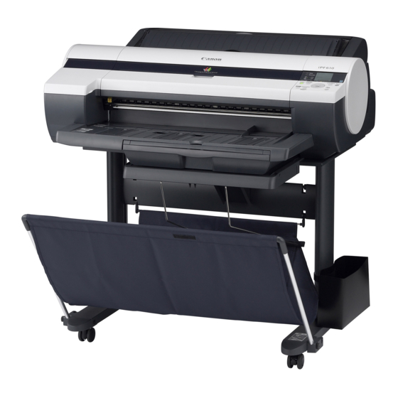
Summary of Contents for Canon iPF610
- Page 1 SERVICE MANUAL DU7-1243-000 OCTOBER 2007 REV. 0 COPYRIGHT ©2007 CANON INC. CANON imagePROGRAF 610 REV. 0 PRINTED IN U.S.A. fineline6...
- Page 2 Conten Contents Chapter 1 PRODUCT DESCRIPTION 1.1 Product Overview....................1 1.1.1 Product Overview....................... 1 1.2 Features......................1 1.2.1 Features........................1 1.2.2 Printhead ........................1 1.2.3 Ink Tank ........................1-4 1.2.4 Cutter ........................... 1-4 1.2.5 Roll Feed Unit ......................1-4 1.2.6 Stand..........................1-6 1.2.7 IEEE1394 (FireWire) Board..................
- Page 3 ontents 1.7.2.3 Handling the Printer ......................1-63 .7.3 Precautions When Servicing Printer ..............1-66 1.7.3.1 Notes on the Data Stored in the Printer ................. 1-66 1.7.3.2 Confirming the Firmware Version ..................1-66 1.7.3.3 Precautions against Static Electricity ................1-66 1.7.3.4 Precautions for Disassembly/Reassembly..............1-66 1.7.3.5 Self-diagnostic Feature .....................
- Page 4 Contents 2.4.2.1 Main controller components....................2-58 2.4.3 Carriage Relay PCB ....................2-60 2.4.3.1 Carriage PCB components ....................2-60 2.4.4 Motor Driver ......................2-61 2.4.4.1 Roll feed unit PCB components ..................2- 2.4.5 Maintenance Cartridge Relay PCB ...............2- 2.4.5.1 Maintenance cartridge relay PCB components ............. 2- 2.4.6 Power Supply ......................2- 2.4.6.1 Power supply block diagram.....................
-
Page 5: Table Of Contents
Contents 4.3.11 Waste Ink Collection Unit..................4-30 4.3.12 Ink Tank Unit......................4-33 4.3.13 Head Management Sensor.................. 4-35 4.3.14 Multi Sensor ......................4-36 4.3.15 PCBs ........................4-36 4.3.16 Opening the Cap/Moving the Wiper Unit............4-39 4.3.17 Opening/Closing the Ink Supply Valve .............. 4-40 .3.18 Draining the Ink ..................... - Page 6 Contents 7.1.1 Service Mode Operation ................... 7-1 7.1.2 Map of the Service Mode..................7-2 7.1.3 Details of Service Mode ..................7-12 7.1.4 Sample Printout......................7-30 7.2 Special Mode ....................7-35 7.2.1 Special Modes for Servicing................... 7-35 Chapter 8 ERROR CODE 8.1 Outline.........................
- Page 7 Chapter 4 DISASSEMBLY/REASSEMBLY fineline6...
-
Page 8: Ink Tank
tents Contents 4.1 Service Parts...................... 4-1 4.1.1 Service Parts....................... 4-1 4.2 Disassembly/Reassembly................4-1 4.2.1 Disassembly/Reassembly..................4-1 4.3 Points to Note on Disassembly and Reassembly ........4-2 4.3.1 Note on locations prohibited from disassembly ............ 4-2 4.3.2 Moving the carriage manually .................. 4-2 4.3.3 Units requiring draining of ink................... -
Page 9: Carriage
Chapter 4.1 Service Parts 4.1.1 Service Parts The service parts indicated below require careful handling. 1. Keep all packages with the warning not to turn over. Pay careful attention to all individually packaged service part (carriage unit, purge unit, ink tank unit, and o parts) boxes marked "This side up"... -
Page 10: Points To Note On Disassembly And Reassembly
hapter 4 Points to Note on Disassembly and Reassembly 1 Note on locations prohibited from disassembly mblies that are prohibited from disassembly and their adjustment outside the factory cannot be conducte ndicated by red screws. t never loosen or remove the red screw, because normal operation and print can't be done if it is loosene moved. -
Page 11: Troubleshooting
Chapter 6 TROUBLESHOOTING fineline6... -
Page 12: Firmware
ontents Contents 6.1 Troubleshooting....................6-1 6.1.1 Outline ..........................6-1 6.1.1.1 Outline of Troubleshooting....................6-1 6.2 Location of Connectors and Pin Arrangement ..........6-2 6.2.1 Main controller PCB....................6-2 6.2.2 Carriage PCB......................6-15 6.2.3 Power supply ......................6-22 6.2.4 Roll feed unit PCB....................6-23 6.3 Version Up...................... -
Page 13: Outline
Chapter 6 6.1 Troubleshooting .1.1 Outline .1.1.1 Outline of Troubleshooting Outline roubles subject to troubleshooting are classified into those shown on the display (warning, error, and service all) and those not shown on the display. Precautions for Troubleshooting 1) Check the environmental conditions and the media used for printing. 2) Before performing troubleshooting, make sure that all connectors and cables are connected properly. -
Page 14: Location Of Connectors And Pin Arrangement
hapter 6 Location of Connectors and Pin Arrangement 1 Main controller PCB J2601 J3101 3 01 J3411 J3402 J3701 J3801 J1101 J1801 J2801 J3211 J3911 J3202 J2712 J1001 J2511 J2703 27 3 J2512 J1201 J3011 F-6-1 T-6-1 J1001 Pin Number Signal name IN/OUT Function... - Page 15 PARTS CATALOG DU7-3164-010 OCTOBER 2007 REV. 1 CANON imagePROGRAF 610 REV. 1 PRINTED IN U.S.A. COPYRIGHT ©2007 CANON INC. fineline6...
- Page 16 Whenever ordering parts, consult this Parts Catalog for all of the information pertaining to each item. Be sure to include, in the Parts Request, the full item description, the item part number, and the quantity. COPYRIGHT (C) 1999 CANON INC. Use of this manual should be strictly supervised to avoid disclosure of confidential information.
-
Page 17: Carriage Unit
Contents NUMERICAL INDEX iPF610/600(Numerical Index) ............1-1 iPF610/600(Parts Catalog) PRINTER & ACCESSORIES ..........2-1 ROLL UNIT ................2-4 COVERS (1) ................2-8 COVERS (2) ................2-12 ELECTRICAL PART ............2-14 PURGE UNIT ...............2-18 CUTTER UNIT ..............2-20 INK SUPPLY UNIT ..............2-22 LINEAR SCALE & LIFT DRIVE UNIT ........2-24 CARRIAGE UNIT ..............2-26...


