Advertisement
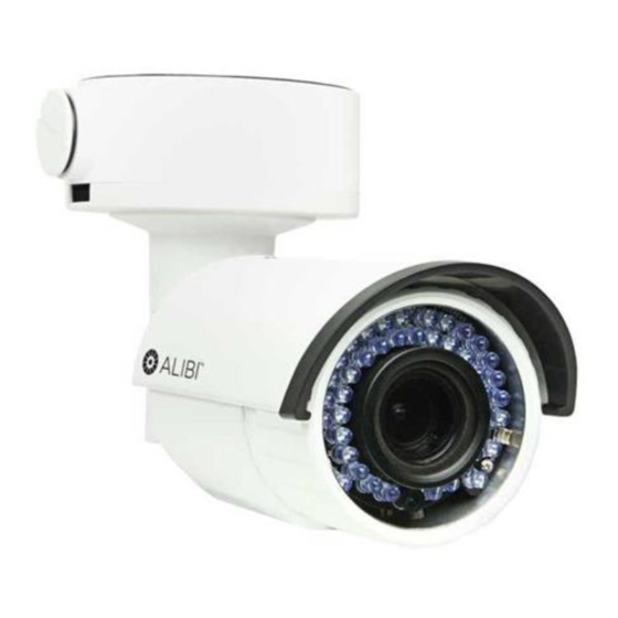
ALI-NS3034R IP 4 MP IR Bullet
Camera Quick Installation Guide
This document guides you through the basic steps to install and initially configure the ALI-NS3034R
camera. The ALI-NS3034R camera features:
1/3" progressive scan CMOS sensor, up to 2688 × 1520 resolution
•
2.8 - 12 mm motorized varifocal lens
•
120 dB True Day/Night (ICR), 3D DNR
•
-22˚F ~ 140˚F operating range
•
Smart IR array, 100 ft range, 850 nm
•
Video analytics: Tamper detection, Line crossing, Intrusion Detection
•
For more information, refer to these documents - available from your equipment vendor:
ALIBI™ Tools Utility Installation and User Manual
•
ALIBI™ Witness and ALIBI™ Witness HD Apps for Android - Quick Start Guide
•
ALIBI™ IP Camera Firmware Version x.x User Manual
•
Articulated
mounting
bracket
Camera body
IR array
Lens
Camera with sun shield and lens cover removed
* Press the RESET button for 10 seconds when the camera is powering on or rebooting to restore the
default settings, including the user name, password, IP address, the port number, etc.
www.observint.com
1
Junction box assembly
(see detail below)
Camera mounting base
Sun Shield
Lens cover
Reset button
SD card slot
Video test cable connector
Camera base
locator pins
Top (up)
Bottom (down)
Conduit port (2)
Junction box detail
What's in the box
Your camera includes these items:
Video test
cable
Weatherproof
LAN coupling
Surface
mount drill
template
Before installing the camera
Make sure the device in the package is in good condition and all the assembly parts are included.
•
Make sure all the related equipment is power-off during the installation.
•
Check the specification of the products for the installation environment.
•
Make sure the power supply is matched with your required voltage to avoid damage.
•
Make sure that the wall is strong enough to withstand three times (12 lb) the weight of the camera.
•
Dust or grease on the lens cover will cause IR reflection. Please do not remove the dome cover film
•
until the installation is finished. If there is dust or grease on the lens cover, clean the it with a clean
soft cloth and isopropyl alcohol.
Step 1.
Install a microSD card
A microSD card installed in the camera provides local storage for log information, capture files, and
recorded video. This information can be downloaded to a network PC by accessing the camera web
interface with Microsoft Internet Explorer (see "Step 5. Login to the camera" on page 4). microSD cards
can be as large as 128GB. To install a microSD card in the camera:
1.
Loosen the sun shield set screw, then lift off the sun shield.
2.
Remove the lens cover from the camera body by unscrewing it counterclockwise (observing it from
the lens end).
3.
Insert a microSD card into the slot shown in the photo to the left.
4.
Push the microSD card into the slot until it clicks into place.
5.
Reattach the lens cover and the sun shield.
Step 2.
Install the camera
The camera includes hardware to install it directly to a mounting surface or to the Junction box provided.
The camera can be installed on a ceiling (horizontal surface) or wall (vertical surface). To install the camera,
do one of the following:
Safety cable hook
Mounting screw
hole (4)
Hole for camera
mounting screw (3)
Cable access
through mounting
surface
Security
L-wrench
CD-ROM
manuals and
software
Mounting
hardware
packet
Junction box
(top view)
ALI-NS3034R_CQ
160315
Advertisement
Table of Contents

Related Manuals for ALIBI ALI-NS3034R


Summary of Contents for ALIBI ALI-NS3034R
- Page 1 (4) Hole for camera mounting screw (3) Top (up) This document guides you through the basic steps to install and initially configure the ALI-NS3034R camera. The ALI-NS3034R camera features: Cable access through mounting 1/3” progressive scan CMOS sensor, up to 2688 × 1520 resolution •...
- Page 2 To mount the camera directly onto a mounting surface Determine the best fasteners for securing the camera to mounting surface. The mounting hardware provided is suitable for most surfaces. Safety cable hook Using the Drill Template provided, mark the location of the mounting screw holes. If mounting the Safety cable camera onto a vertical surface, orient the Drill Template so it is vertical, as shown in the photo above (see What’s in the box).
- Page 3 Step 4. Install the Alibi Discovery Tool Alibi Discovery Tool is a software utility used to “discover” Alibi cameras and NVRs/DVRs installed on the physical Ethernet network (LAN) and change their network settings. Discovery Tool is provided on the CD with your camera and is contained in Alibi Power Tools.
-
Page 4: Step 5. Login To The Camera
Step 5. Login to the camera If this login is the first login to an Alibi camera from your computer and browser, continue with the following sub-steps to install WebComponents: To access the camera from a computer on the LAN:... -
Page 5: Step 6. Remote Live View Screen
Tilt Rotation lock screw Rotation Pan lock screw Installing the WebComponents plugin may require that you close the browser. Follow the on-screen instructions, then restart your browser and log in after the installation is finished. Tilt lock screw Allow the plug-in installation to complete. When the following window appears, click Finish. -
Page 6: Specifications
0 ~ 100 either by moving the slider or entering the value in the box on the right. The effect of the Audio adjustment will appear in the Live View image in the menu. Audio Streaming Two-way Exposure Settings submenu: In this submenu, set the following for the best performance: •...
Need help?
Do you have a question about the ALI-NS3034R and is the answer not in the manual?
Questions and answers