
Related Manuals for JRC JMA-1030 Series


Summary of Contents for JRC JMA-1030 Series
- Page 1 JMA-103 1030Series Series MARINE RADAR MARINE RADAR EQUIPMENT EQUIPMENT INSTRUCTION INSTRUCTION MANUAL MANUAL...
- Page 3 IRST-AID T REATMENT ECAU UTION NS B EFOR RE O OPERA ATIO Cauti ions for H High Volta High v voltages, ra anging from m several h hundreds t to tens of thousands of volts, a are used in electro onic appara tus, such a s radio and...
- Page 4 FIRST-AID TREATMENTS FIRST-AID TREATMENTS Method of First-Aid Treatment Precautions for First-Aid Treatments Apply artificial respiration to the person who collapsed, minimizing moving as much as possible avoiding risks. Once started, artificial respiration should be continued rhythmically. (1) Refrain from touching the patient carelessly as a result of the accident; the first-aider could suffer from electrical shocks by himself or herself.
- Page 5 IRST-AID T REATMENT Treat tment to Giv ve Wh hen the e Pati ent H as a Pulse Beati ing bu ut Has s Ceas sed to Breat ∗ Performin ng mouth-to o-mouth ar rtificial resp piration - F Fig. 1 Bend th he patient's face backw...
- Page 6 FIR RST-AID TR REATMENT Treatm ment to o Give When n the P Patient t Has N Pulse Beatin ng and d Has Cease ed to B Breath ∗ P erforming cardiac ma assage - F Fig. 2 If th he patient ha as no pulse e beating, w...
- Page 7 IRST-AID T REATMENT Proc edure fo or Cardio opulmona ary Resu uscitatio n (CPR) Using th he AED (Aut tomated Externa l Defibril llator) A person is co ollapsing. - Secure the safety of the surrounding a area. - Prevent se condary disas sters.
- Page 8 RST-AID TR REATMENT Proc edure fo or Cardio opulmona ary Resu uscitation n (CPR) Using th he AED (Aut tomated Externa l Defibril llator) 1. Che eck the sce ene for safe ety to prev vent second dary disast ters a) D Do not touch the injured...
- Page 9 IRST-AID T REATMENT 7. Giv ve 2 rescue e breaths (o omittable) If opening th he airway do oes not caus se the injure ed or ill perso on to begin to bre eathe norma lly, give resc cue breaths CPR mask If there is a f fear of infec...
- Page 10 RST-AID TR REATMENT 9. Whe en to stop cardiopulm monary res suscitation n (CPR) a) W When the in njured or ill p person has b been handed d over to the emergency services b) W When the in njured or ill p person has s started moan ning or brea...
- Page 11 IRST-AID T REATMENT 14. Re esume card diopulmon ary resusc citation (CP PR). esume CPR consisting o of 30 chest co ompressions s and 2 rescu reaths by foll owing the vo oice prompts s of the AED. 15. Au utomatic el lectrocardi ogram ana...
-
Page 12: Preface
PREFACE / CHECKING THE SUPPLIED ITEMS PREFACE Thank you very much for purchasing the JRC marine radar equipment, JMA-1030 series. This equipment is a marine radar equipment designed to obtain safe operation of marine ships. This equipment consists of a scanner unit and a display unit as its main units. -
Page 13: Before Operation
BEFORE OPERATION BEFORE OPERATION PICTORIAL INDICATION Various pictorial indications are included in this manual and are shown on these equipment so that you can operate them safety and correctly and prevent any danger to you and/or to other persons and any damage to your property during operation. Such indications and their meanings are as follows. - Page 14 BEFORE OPERATION RUSSIA CTP MARK According to the requirements of clause 20 of Technical Regulations about safety of Maritime transport objetcs, approved by Resolution of the Russian Federation Goverment #620 dated August 12, 2010 and requirements Technical Regulation of the Russian Federation Goverment #623 dated August 12, 2010 navigation &...
- Page 15 PRECAUT TIONS PRE CAUT TION Neve er carry out t internal in spection or r repair wor rk of the eq uipment by y users. Insp ection or repair wor k by unau uthorized p ersonnel m may result in fire haza ard or electr ric shock.
- Page 16 PREC CAUTIONS ver directly y touch the internal co mponents o of the anten nna, ceiver/trans sceiver, or in ndicator. rect conta with these voltage compon nents cause ectrocution. For maint tenance, in nspection, or adjustm ment of eq quipment mponents, consult wi th our bran...
- Page 17 PRECAUT TIONS malfunction may occu ur if the p power in t the ship is s instantan neously inter rrupted dur ring operati ion of the r radar. In thi s case, the e power sho ould be turn ed on again Alwa ays use the e automatic...
- Page 18 PREC CAUTIONS Sinc ce these a alarms may y include s some error rs dependi ng on the target trac king condi tions, the navigation officer him mself shou ld make th he final deci ision for sh hip operatio ons such as s collision a avoidance.
-
Page 19: Warning Label Mounting Point
WARNING LABEL MOUNTING POINT WARNING LABEL MOUNTING POINT Warning label is patched on the equipment visible surface. Do not try to remove, break or modify the label. NKE-1066 SCANNER UNIT NKE-2044 SCANNER UNIT NCD-2256 DISPLAY UNIT xvii... - Page 20 PACK KING LIST KING G LIST The packin ng lists of ea ach unit are e as follows NCD-225 56: DISPLA AY UNIT Part ts Name Figure Disp lay Unit [NCD D-2256] Cover [MTV V305222*] Powe er Cable [CFQ Q-9900] Instr uction Man nual...
- Page 21 PACKING G LIST NKE-204 4: SCANN NER UNIT rts Name Figure Scan nner Unit [NKE E-2044] Bolt Moun nting [M8X30 0 SUS304] Hard ware Spring Washer [SW8 S SUS] [MPX XP35114*] Washer [W8 SU Instruc tion for Equipm ment [MTZ30 04691*] Temp plate...
-
Page 22: Equipment Appearance
Individual TYPE name is changed by combination of units. TYPE JMA-1032 NCD-2256 NKE-1066 TYPE JMA-1034 NCD-2256 NKE-2044 JMA-1030 Series system diagram 1.5feet Scanner Unit 2feet Scanner Unit (NKE-2044) (NKE-1066) Radome diameter 620mm Radome diameter 450mm Installation cable: CFQ9924-5, 10, 15, 20, 30... - Page 23 EQUIPMENT APPEARANCE NKE-1066 SCANNER UNIT NKE-2044 SCANNER UNIT...
- Page 24 EQUIP PMENT APP PEARANCE NCD-22 256 DIS SPLAY U UNIT SUN C COVER TOU U CH PANE FRON T PANEL REAR C CASE Fingertip p position Thumb po osition Note: W When you re emove the s sun cover do MOUNTING he thumb po osition push...
-
Page 25: Table Of Contents
CONTENTS CONTENTS PREFACE ........................x CHECKING THE SUPPLIED ITEMS ................ x BEFORE OPERATION ..................... xi PRECAUTIONS ...................... xiii WARNING LABEL MOUNTING POINT ............... xvii PACKING LIST ..................... xviii EQUIPMENT APPEARANCE ................. xx CONTENTS ......................xxiii GLOSSARY ......................xxix Chapter 1 INSTALLATION ..................1 1.1 OVERVIEW .......................... -
Page 26: Contents
CONTENTS Chapter 3 ADJUST THE RADAR ECHO ............44 3.1 CHANGE RANGE ........................44 3.2 SENSITIVITY ADJUSTMENT ....................45 3.3 SEA CLUTTER SUPPRESSION ................... 46 3.4 RAIN/SNOW CLUTTER SUPPRESSION ................47 3.5 SCREEN BRILLIANCE (another operation) ................48 Chapter 4 VRM AND EBL FUNCTION ..............50 4.1 OPERATION OF VRM, EBL .................... - Page 27 7.8.3 SPEED EQUIPMENT ....................89 7.8.4 MANUAL SPEED ......................89 7.8.5 MAGNETIC COMPASS ....................89 7.9 JRC GPS ( for future enhancements) ..................90 7.9.1 GPS STATUS DISPLAY ....................90 7.9.2 GPS SETTING ......................91 7.9.3 BEACON SETTING ..................... 95 7.9.4 SBAS SETTING ......................
- Page 28 CONTENTS 8.1.6 RADAR ALARM LEVEL ....................99 8.2 TT FUNCTION ........................100 8.3 SCANNER FUNCTION ......................101 8.3.1 PULSE REPETITION FREQUENCY FINE TUNING (PRF FINE TUNING) .... 101 8.3.2 STAGGER TRIGGER ....................101 8.3.3 ANTENNA ROTATION SPEED ................102 8.3.4 PRF MODE ........................ 102 8.3.5 TIMED TX ........................
- Page 29 CONTENTS 9.2.2 SCANNER NKE-2044....................120 9.2.3 DISPLAY NCD-2256 ....................120 9.3 PERFORMANCE CHECK ....................121 9.3.1 TEST MENU ......................122 9.3.2 SYSTEM INFORMATION..................122 9.3.3 SYSTEM TIME ......................122 9.3.4 SCANNER INFORMATION ..................123 9.3.5 HARDWARE INFORMATION ................... 123 9.3.6 ERROR LOG ......................123 9.3.7 LINE MONITOR ......................
- Page 30 CONTENTS 12.6.1 INTEGRATED DISPLAY UNIT (NCD-2256) ............142 12.6.2 OPERATIONAL PART .................... 143 12.6.3 AIS FUNCTION (STANDARD BUILT IN) ..............144 12.6.4 TT FUNCTION (STANDARD BUILT IN) ..............144 12.7 INPUT/ OUTPUT SIGNAL ....................144 12.7.1 INPUT ENABLE SIGNAL ..................144 12.7.2 OUTPUT POSSIBLE SIGNAL .................
-
Page 31: Glossary
GLOSSARY GLOSSARY This section describes the main terms used for this equipment and general related maritime terms. Activated target A target representing the automatic or manual activation of a sleeping target for the display of additional information. Automatic Identification System A system which enables ships and shore stations to obtain identifying and navigation information about other ships at sea, using an automated transponder. - Page 32 GLOSSARY fathom 1fm=1.8288m Fast Time Constant Function of FTC reduces the effect of long duration returns that come from rain or snow. Global Positioning System GPS is a space-based satellite navigation system that provides location and time information in all weather conditions. Ground stabilization A display mode in which speed and course information are referred to the ground, using ground track input data.
- Page 33 GLOSSARY Parallel Index line Past positions Equally time-spaced past position marks of a tracked or AIS target and own ship. POSN Position Pulse Repetition Frequency The number of radar pulses transmitted each second. PROC Process Radar signal processing function Radar Acronym for RAdio Detection And Ranging Radar beacon A navigation aid which responds to the radar transmission by generating a radar signal to...
- Page 34 GLOSSARY Short Pulse STAB Stabilization Sensitivity Time Control Function of STC reduces the impact of returns from sea state of relatively near from own ship. Speed Through Water The speed of the ship relative to the water surface. TCPA Time to Closest Point of Approach to own ship Test target Radar target of known characteristics used for test requirement True Motion...
-
Page 35: Chapter 1 Installation
It is preferable to install the display unit in the wheel house to facilitate observations. Available cable lengths and types for installing the radar JMA-1030 are as shown in the table below. Request an appropriate cable from JRC beforehand. A cable longer than the sufficient length may degrade radar performance, so give it careful consideration when planning the installation. -
Page 36: Installation Of The Display Unit
Chapter 1 INSTALLATION 1.2 INSTALLATION OF THE DISPLAY UNIT 1.2.1 SELECTING THE INSTALLATION POSITION Select the display unit installation position by taking into consideration of the followings. ■ Install the display unit so that the user can easily conduct observations. ■... -
Page 37: Dimensional Drawing Of Display Mounting
Chapter 1 INSTALLATION 1.2.3 DIMENSIONAL DRAWING OF DISPLAY MOUNTING... - Page 38 Chapter 1 INSTALLATION...
-
Page 39: Examples Of Display Mounting
Chapter 1 INSTALLATION 1.2.4 EXAMPLES OF DISPLAY MOUNTING ■ DESK TOP INSTALLATION Mounting bracket... - Page 40 Chapter 1 INSTALLATION DESKTOP MOUNTING TEMPLATE Note: Please note the paper size.
- Page 41 Chapter 1 INSTALLA ATION FLUS SH MOU NTING Front cap Note: P Please slide o out, when re e moving of t the front cap Flush mou unt: Remove b base, and ta ake out cove er of front pa anel Fix with th he front 4 co...
- Page 42 Chapter 1 INSTALLATION FLUSH MOUNTING TEMPLATE Note: Please note the paper size.
- Page 43 Chapter 1 INSTALLATION CEILING INSTALLATION Option: Overhead Mounted Kit Note: Please slide out, when removing of the front cap. Front cap...
-
Page 44: Power Cable Installation
Chap pter 1 INST TALLATION 1.2.5 POWER R CABL LE INST TALLAT This equipm ment include es a 2m pow wer cable for r power supp ply to the dis splay unit. Cable assembly n ame: CFQ-9 9900 The cable c core wire co olor is red (+ ), black (-), s... -
Page 45: External Navigational Signal Connection
In case of using option NMEA cable, waterproofing (IPX5) is guaranteed. Thus using another NMEA cable, waterproofing (IPX5) is not guaranteed. ・Using JRC GPS receiver, please connect NMEA1. ・Using JRC NSK, please connect NMEA3. ・AIS connects all NMEA port available. -
Page 46: Installation Of The Scanner Unit
Chap pter 1 INST TALLATION 1.3 IN NSTAL LLATIO ON OF T THE SC CANNE ER UNI 1.3.1 SELEC TING T HE INST TALLAT TION PO OSITION PHYS SICAL S ELECTIO ON CRIT ERIA Install the e scanner at t the center of the mast on the keel line. -
Page 47: Mounting Rack And Mast For The Scanner
Chapter 1 INSTALLATION 1.3.3 MOUNTING RACK AND MAST FOR THE SCANNER If it is considered that sufficient installation height cannot be provided when the scanner is installed directly on the roof of the wheelhouse, use a mounting rack or radar mast (Fig. 1-3-3). Normally, when the scanner installation height is less than 2 meters from the roof of the wheelhouse, provide a mounting rack assembled at an angle frame to install the scanner. -
Page 48: Ensuring View Angle
Chapter 1 INSTALLATION When installing two scanners, provide a height difference so that those two scanners do not enter each other's vertical beam width range. To avoid interference with other equipment and to prevent radio noise from generating, do not place the VHF antenna, GPS antenna, and INMARSAT's dome within the range of the vertical beam width. - Page 49 Chapter 1 INSTALLATION ■ Confirmation during test run If the scanner vibrates a lot during test run, try to reduce or prevent vibration by reinforcing the scanner mount base or using wire stays attached to the radar mast. Others The design of the mounting platform for the scanner should take into account the vibration requirements defined by IEC 60945.
-
Page 50: Confirm Mounting Base Before Install
Chapter 1 INSTALLATION 1.3.6 CONFIRM MOUNTING BASE BEFORE INSTALL NKE-1066 1.5FT SCANNER 4-φ40 RUBBER PLATE Fig 1-3-6-1 Fig 1-3-6-2... - Page 51 Chapter 1 INSTALLATION NKE-2044 2FT SCANNER Fig 1-3-6-3 Fig 1-3-6-4...
- Page 52 Chapter 1 INSTALLATION Installation and clamping method ■ Installation direction Installation should be done so that the cable gland is oriented toward the stern. ■ Bolts, nuts and tightening torque to be used Use stainless steel bolts for the scanner and uniformly tighten all of the bolts (Table 1-3-6-1). Table 1-3-6-1 Length of scanner mounting bolts and tightening torque Thickness of Mount Base (mm) Bolt...
-
Page 53: Connecting The Installation Cable
Chapter 1 INSTALLATION 1.4 CONNECTING THE INSTALLATION CABLE With this new radar, JRC introduces two new small and light weight 4kW multi-speed scanners available in a 1.5ft (450mm) and 2ft (620mm) radome. Both of them are the radome type, so antenna rotation is not affected by wind. -
Page 54: Nke-1066 Scanner (1.5 Feet)
Chapter 1 INSTALLATION 1.4.1 NKE-1066 SCANNER (1.5 FEET) Set the cable inlet side to face the stern. The scanner certainly can be placed to face any direction during the initial setting. However, it is strongly recommended that you install the scanner with the shortest cable length along the mast. - Page 55 Chapter 1 INSTALLATION Fig. 1-4-1-3...
- Page 56 Chap pter 1 INST TALLATION N When mou unting the s scanner uni it, please c heck the m maximum le ength of the holding bo olts. If the b bolts are to o long, it g gives severe e damage t to inside of the scanne er.
- Page 57 Chapter 1 INSTALLA ATION Coating clip nnect cable mesh wire a as Ground. Pull and fix the cable e toward the e outside with coat ting clip. (Avoid to o touch the c cable to elec ctrical parts) g. 1-4-1-4 Close radome Attach...
-
Page 58: Nke-2044 Scanner (2 Feet)
Chapter 1 INSTALLATION 1.4.2 NKE-2044 SCANNER (2 FEET) Set the cable inlet side to stern. (Any direction is possible to install and possible to initial setup, but it is better selection to select the cable length must be minimize along the mast.) Ship heading stern Fig. - Page 59 Chapter 1 INSTALLATION Fig. 1-4-2-3...
- Page 60 Chap pter 1 INST TALLATION N When mou unting the s scanner uni it, please c heck the m maximum le ength of the holding bo olts. If the b bolts are to o long, it g gives severe e damage t to inside of the scanne er.
- Page 61 Chapter 1 INSTALLATION Fig. 1-4-2-4 Clamp the cable Connect cable mesh wire as Ground. Close radome Attach the radome. Set to fit the triangle mark of the upper and lower radome. In the following order, on the diagonal, tighten gradually in order to press uniformly packing.
-
Page 62: Chapter 2 Start The Basic Operation
Chapter 2 START THE BASIC OPERATION Chapter 2 START THE BASIC OPERATION If the basic adjustment is made by the serviceman beforehand, please run it as it is. (In the case of no adjustment is done by the serviceman beforehand, you had better grasped the operation of this radar through referring to Chapter 5, then please perform the initial settings that are listed in Chapter 7.) The high definition 7-inch wide display has a touch panel and can be operated by tracing a screen by means of a finger or touch pen. -
Page 63: Panel And Screen Display Layout
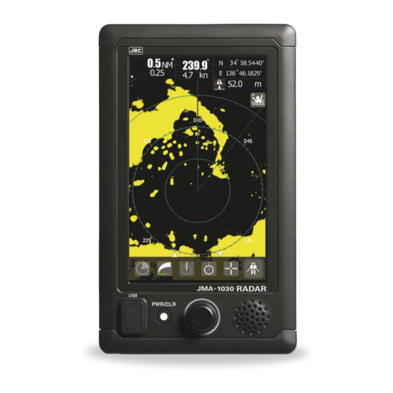
Chapter 2 START THE BASIC OPERATION 2.1 PANEL AND SCREEN DISPLAY LAYOUT Heading SPD (base on ground)*1 Range Scale Range Interval Numerical Information Alarm Range Ring Heading Line Bearing Scale Motion Mode Bearing Mode *1: In case of only input of VHW, it indicates speed through the water Name Description Touch Panel... -
Page 64: Power On/Off
Chap pter 2 STA ART THE BA ASIC OPER RATION 2.2 P POWER R ON/O A malfunc ction may occur if th he power in the shi ip is insta antaneously interrupted d during op peration of t the radar. I n the case, , the power r should be... - Page 65 Chapter 2 START THE BASIC OPERATION Starting transmission Stopping transmission...
-
Page 66: Screen Layout
Chap pter 2 STA ART THE BA ASIC OPER RATION Powe er off Press the P WR/CLR ke ey 3 seconds s or more. 2.3 S SCREE N LAY YOUT 2.3.1 STAND DBY SCR REEN Startu up screen (Startup s screen ca an be selec cted from... - Page 67 Chapter 2 START THE BASIC OPERATION Tap on the screen to select graphical display screen.
- Page 68 Chap pter 2 STA ART THE BA ASIC OPER RATION Vario us STBY s screens a and Icon m menu Normal s screen Flick up Flick up Flick up Flick down Flick k down ick down Graphica al screen Flick up Flick up Flick down lick down...
-
Page 69: Transmission Screen
Chapt er 2 STAR RT THE BAS SIC OPERA ATION 2.3.2 TRANS SMISSIO ON SCR REEN Flick up Tran nsmitting Flick up lick Flick down Tap the T X/STBY ico Abou ut 10 second ds, the icons s fade out. Push the ro otary knob o or flick the sc... -
Page 70: Display The Function Icons
Chap pter 2 STA ART THE BA ASIC OPER RATION 2.3.3 DISPLA AY THE FUNCT TION ICO Push the e rotary knob to display t the icons. No oper ration about 10 s seconds, the icon s fade out. Turn rotary k k nob Push rot ary knob ・Turn... - Page 71 Chapt er 2 STAR RT THE BAS SIC OPERA ATION Tap the GA AIN icon, or push the rot tary knob wh hen the GAI N icon is foc cused. The case of STBY he case of T Adjus stment Bar Adjustme ent Bar is sho...
- Page 72 Chap pter 2 STA ART THE BA ASIC OPER RATION Tap the SE EA icon, or p push the rota ary knob wh en the SEA icon is focu used. Please u use normally y the MANUA AUTO is s suitable for r bad weathe er that the adjustme...
- Page 73 Chapt er 2 STAR RT THE BAS SIC OPERA ATION Tap the RA AIN icon, or push the rot tary knob wh hen the RAI N icon is foc cused. Please e use norma ally the MAN NUAL. AUTO O is suitable for bad wea ather that the adjust...
-
Page 74: Brief Explanation Of Icon's Function
Chap pter 2 STA ART THE BA ASIC OPER RATION 2.4 B BRIEF E EXPLA ANATIO ON OF ICON’S S FUNC CTION Brief explan nation of ea ch icon. GAIN (g gain control) ) adjustment Set up t the sensitivit ty of Radar echo. - Page 75 Chapt er 2 STAR RT THE BAS SIC OPERA ATION Off-cent ter (Normally y own positi on is the ce nter of scree en, but it is p possible to m move own position from fixed c center of scr reen).
- Page 76 Chap pter 2 STA ART THE BA ASIC OPER RATION GUARD Z ZONE setup Set up th e watching area around d own-ship. If a targe t goes into t the set-up ar rea, generat te the alarm m sound or si ignal..
-
Page 77: Setting The Resident Icons
Chapter 2 START THE BASIC OPERATION 2.5 SETTING THE RESIDENT ICONS Specified icons can be copied to All of the icons are the favorite icon area. displayed. You can line up your favorite function icons Fixed icons in this area. (4 or less) (TX/STBY, Gain) How to copy icon Tap and hold the icon... -
Page 78: Chapter 3 Adjust The Radar Echo
Chap pter 3 ADJ UST THE R RADAR ECH Chap pter 3 3 AD DJUS ST TH HE RA ADAR R ECH 3.1 C CHANG GE RAN This pi cture is sele ected 1.5NM M range. Outer dashed line e shows the e range of s selected ran nge. -
Page 79: Sensitivity Adjustment
hapter 3 A ADJUST TH HE RADAR ECHO 3.2 S SENSIT TIVITY A ADJUS STMEN It is neces ssary to set an appropri iate gain lev vel in order t o use the ra adar exactly. Failure to o do so, it is possible to o obtain an ac ccurate rada... -
Page 80: Sea Clutter Suppression
Chap pter 3 ADJ UST THE R RADAR ECH 3.3 S SEA CL LUTTER R SUP PRESS SION It is nece essary to ad just the sea clutter supp pression lev vel in order to o use the rada r exactly. Fa ailure to do s so, it is poss sible to obta... -
Page 81: Rain/Snow Clutter Suppression
hapter 3 A ADJUST TH HE RADAR ECHO 3.4 R RAIN/S NOW C CLUTT ER SU PPRES SSION It is neces ssary to adju ust the rain/ /snow clutter r suppressio on level in or rder to use the radar exactly. -
Page 82: Screen Brilliance (Another Operation)
Chap pter 3 ADJ UST THE R RADAR ECH 3.5 S SCREE N BRIL LLIANC CE (ano other o operati he brightness s adjustmen nt menu app pear by tapp ing brightne ess adjustme ent icon, t it will appe ear when yo u double-tap p on the scre... -
Page 83: Change Range
Chapter 3 ADJUST THE RADAR ECHO ****FOR REFERENCE**** In order to obtain an accurate radar echo, sea clutter suppression adjustment and gain adjustment are essential. RAIN: Normally is set to “0”. But in the case of rain or snow, you need use the rain clutter suppression function to remove the noise appearing on the screen. -
Page 84: Chapter 4 Vrm And Ebl Function
Chap ter 4 VRM M AND EBL FUNCTION Chap pter 4 4 VR RM A ND E EBL F FUNC CTION 4.1 O OPERA ATION O OF VRM M, EBL VRM: Flick k on the scre een, VRM rin ng can be m moved to the specified ta arget. -
Page 85: Example Of Ebl Function
Chapter 4 VRM AND D EBL FUNC CTION 4.3 E EXAMP PLE OF F EBL F FUNCT TION Exampl e: EBL func ction. Target be earing is dis splayed. Menu bar d disappears a after about 1 10 seconds. How to c hange the e EBL Flick o... -
Page 86: Chapter 5 Various Function Icons
Chapt ter 5 VARI IOUS FUNC CTION ICON Chap pter 5 5 VA ARIO US F UNCT TION ICON 5.1 M MOB FU UNCTIO ON (MA AN OV VERBOA ARD) To use this s function, sh hip’s position n informatio n is required Due to th he movemen... -
Page 87: Off-Center Function
hapter 5 V VARIOUS FU UNCTION IC CONS 5.2 O OFF-CE ENTER R FUNC CTION It is poss ible to shift t the center o of own ship i n order to o bserve a pa articular targe et in a wider range. -
Page 88: Cursor Function
Chapt ter 5 VARI IOUS FUNC CTION ICON 5.3 C CURSO OR FUN NCTION ing the curso or function c can read out t a selected target inform mation. p the cursor icon. Tap a anywhere on n the screen , the cursor mark is disp... -
Page 89: Guard Zone Function
hapter 5 V VARIOUS FU UNCTION IC CONS 5.4 G GUARD D ZONE E FUNC CTION To use this s function, sh hip’s headin g informatio on is required ard zone fun ction used t to detect an echo movem ment in the warning are ea. -
Page 90: Radar Trails
Chapter 5 VARIOUS FUNCTION ICONS 5.5 RADAR TRAILS This “radar trails” function can be used to figure out how well you can navigate an obstacle and how well you can keep the bearing that have set for your boat. The echo trail is displayed on the radar display screen so you can easily assess visually what is going on. -
Page 91: Setup The Radar Trails Ref Level, Etc
Chapter 5 VARIOUS FUNCTION ICONS 5.5.2 SETUP THE RADAR TRAILS REF LEVEL, etc You can be selected in the range of trail length set by 5.5.1. - Page 92 Chapter 5 VARIOUS FUNCTION ICONS **** **** FOR REFERENCE Trails REF Level REF Level1 is the lowest level while “REF Level4” is the highest level. When radar trails are plotted with unwanted waves, change to a higher level. To thin radar trails, change to a higher level. If radar trails are plotted in snatches, change to lower level.
-
Page 93: Ais Operations
hapter 5 V VARIOUS FU UNCTION IC CONS 5.6 A AIS OP ERATI To use this s function, sh hip’s headin g, position a and AIS info rmation are required. The AIS fun nction show ws the targets s informatio n on the rad dar display, u using other... -
Page 94: Tt Operations
Chapt ter 5 VARI IOUS FUNC CTION ICON The specifi ed target da ata is display yed. BRG and R RNG shows the relative positional in nformation w which is obse erved from th he own ship p. COG and shows grou und speed a and ground c... - Page 95 hapter 5 V VARIOUS FU UNCTION IC CONS Tracki ng target This s ymbol is dis splayed for t he target wh hich become es the tracki target after acquir red. This is s displayed w with a circle of thick line e (basic colo or is white).
-
Page 96: Mode Function
Chapter 5 VARIOUS FUNCTION ICONS 5.8 MODE FUNCTION Mode function can be set according with different situations. The settings for each mode are following. Mode Name Standard Coast Float River Setting Contents Middle Middle Middle Middle Middle Process 5Scan COREL Target Enhance Level1 Level2... -
Page 97: Switching Day / Night Mode
Chapter 5 VARIOUS FUNCTION ICONS 5.9 SWITCHING DAY / NIGHT MODE Combination of the display color and brilliance according to the ambient lighting conditions is provided. The display color setting can be changed easily. -
Page 98: User Option Key
Chapter 5 VARIOUS FUNCTION ICONS 5.10 USER OPTION KEY For example, it sets User option key on Tuning menu. It is possible that you can give your favorite function to the option key . By using the option key, you can open the heavily used menu in one operation. You can set a function listed in the “bar menu”... -
Page 99: Mark Function
Chapter 5 VARIOUS FUNCTION ICONS 5.11 MARK FUNCTION 5.11.1 MEMO You can use “Memo” function to draw simple memos on the screen. You can change the color and line width of memos. You can undo and redo the memos. You can delete all the memos by tapping the clear bar. You can select a marker to display by tapping the view menu bar. -
Page 100: Line Function
Chapter 5 VARIOUS FUNCTION ICONS 5.11.2 LINE FUNCTION To use this function, ship’s heading and position information are required. - Page 101 Chapter 5 VARIOUS FUNCTION ICONS You can use “Line” function to draw some lines on the screen. There are some differences between “Memo” function and “Line” function as following. “Line” function is linked to a change of the range. “Memo” function does not. To use “Line”...
-
Page 102: Symbol Marker
Chapter 5 VARIOUS FUNCTION ICONS 5.11.3 SYMBOL MARKER To use this function, ship’s heading and position information are required. To use the “Symbol marker” function, GPS signal input is necessary because symbol position is memorized as a latitude and longitude data. If no GPS signal is input, you cannot select “Symbol marker” function. You can select the following symbols. -
Page 103: Radar Echo
Chapter 5 VARIOUS FUNCTION ICONS 5.12 RADAR ECHO It is used when you want to adjust the settings of your favorite radar image. -
Page 104: Pulse Length
Chapter 5 VARIOUS FUNCTION ICONS 5.12.1 PULSE LENGTH The transmission pulse length is changed by adjusting the range. Range Pulse Length(JMA-1032) Pulse Length(JMA-1034) 0.0625NM 0.125NM 0.25NM 0.5NM SP1/MP1 SP1/MP1 0.75NM SP2/MP1 SP2/MP1 SP2/MP1 SP2/MP1 1.5NM SP2/MP1/MP2 SP2/MP1/MP2 SP3/MP1/MP2 SP3/MP1/MP2 SP3/MP1/MP2 SP3/MP1/MP2 SP3/MP1/MP2 SP3/MP1/MP2... -
Page 105: Target Enhance
hapter 5 V VARIOUS FU UNCTION IC CONS 5.12.3 TARG GET ENH HANCE The dimens sion of video o display is e enlarged by y the target e enhancemen nt function. A And radar ec cho display two targets s is closing in n angle and distance. -
Page 106: Video Noise Rejection
Chapter 5 VARIOUS FUNCTION ICONS 5.12.6 VIDEO NOISE REJECTION This function rejects signals that assumed as noise and clutter in radar videos. OFF: Turns off the noise rejection function, and displays all signals. Targets are popped up from noise and displayed like analog signals. -
Page 107: Tuning
Chapter 5 VARIOUS FUNCTION ICONS 5.13 TUNING Automatic tuning mode (AUTO) and manual tuning mode (MANUAL) are provide. In the automatic tuning mode, transmission and receiving frequencies are tuned and adjusted automatically. In the manual tuning mode, tuning is carried out by yourself. When “AUTO”... -
Page 108: Motion Mode
Chapter 5 VARIOUS FUNCTION ICONS 5.14 MOTION MODE Motion: Switches between true and relative motion display modes. The bearing signal input is required to display true motion. In the true motion display mode, the own ship’s position on the radar screen moves depending on its speed and course and the influence of the current. -
Page 109: Vector Length
Chapter 5 VARIOUS FUNCTION ICONS 5.15 VECTOR LENGTH Sets TT and AIS vectors. The bearing and speed signal input are required to display TT and AIS vectors. In the True vector mode, the direction of a target vector indicates the true course of the target and its vector length is proportional to its speed. -
Page 110: Target
Chapter 5 VARIOUS FUNCTION ICONS 5.17 TARGET It is used when you want to set about function of target tracking function (TT) and AIS. -
Page 111: Function On/Off
hapter 5 V VARIOUS FU UNCTION IC CONS 5.17.1 FUNC TION O ON/OFF Turns ON/O OFF TT func ction and AI S function. 5.17.2 CPA L LIMIT Set and che eck collision n decision cr riteria before e operating. The CPA L Limit value ca an be set be etween 0.1 a... -
Page 112: Nmea Info. Set
Chapter 5 VARIOUS FUNCTION ICONS 5.18 NMEA INFO. SET Set the NMEA information displayed in upper right are. NMEA information also can be changed by tapping upper right are. It is possible to display the 6 combinations as following. Depth Temperature Latitude/Longitude Latitude/Longitude... -
Page 113: External Monitor Output
Chap pter 6 OPT TION FUNC TIONS Chap pter 6 6 OP PTION N FU NCTI IONS 6.1 E EXTERN NAL M MONITO OR OUT TPUT If you inst talled the E External mo onitor outpu ut, waterpro oofing (IPX5 5) of rear side of dis splay unit i... -
Page 114: Chapter 6 Option Functions
Chapter 6 OPTION FUNCTIONS 6.2 NMEA CABLE The JMA-1030 series has 3 channels NMEA signal input allowing connecting to navigation equipment, such as GPS, for own position, waypoints and speed for MARPA tracking. It also allows connecting a GPS compass for your heading (and MARPA tracking) and / or AIS for displaying targets. -
Page 115: Chapter 7 Initial Settings
Chapter 7 INITIAL SETTINGS Chapter 7 INITIAL SETTINGS An initial adjustment had been done for this radar at the factory. This product will be shipped in a usable state. However, in the case you want to configure it with your favorite, please set it by referring to this chapter. It is recommended that you save to USB memory (see 8.5.6.1) or you keep a note of the setting by the user for return to the previous setting. -
Page 116: Language Selection
Chap ter 7 INITI IAL SETTIN 7.1 L LANGU UAGE S SELECT TION Choose a a familiar lan nguage. Tap “Langua age” bar. If you choo ose the langu uage that yo ou can’t und erstand, it is s able to retu urn to the En nglish menu u to input “22... -
Page 117: Bearing Adjustment
Chapter 7 INITIAL SETTINGS 7.3 BEARING ADJUSTMENT Adjust the bearing so that bearing of the target measured with the ship’s compass matches that of the target echo on the radar display. Before adjustment Measure the bearing of an adequate target (for example, a ship at anchor, a breakwater or a buoy) relative to own ship’s heading. -
Page 118: Antenna Height Set Up
Chapter 7 INITIAL SETTINGS 7.5 ANTENNA HEIGHT SET UP Set up the antenna height. This set up is related to sea clutter rejection control, At a short range, sea clutter level is proportion to the height of the scanner. So an optimum sea clutter rejection constant must be selected according with the height of antenna. 7.6 NOISE LEVEL The noise level had been adjusted at the factory. -
Page 119: Communication Port Setup
Chapter 7 INITIAL SETTINGS 7.7 COMMUNICATION PORT SETUP Set up the communication port to communicate external device. 7.7.1 BAUD RATE Data speed setting of communication. Auto: Switching automatically between 4800bps and 38400bps. -
Page 120: Rx Port
Chapter 7 INITIAL SETTINGS 7.7.2 RX PORT Choose the receive port of each signal. It sets to automatic when there is no particular problem. Auto: Switching automatically between NMEA1, NMEA2, and NMEA3. 7.7.3 TX PORT Choose the transmit port of each signal. -
Page 121: Tx Data Format
Chapter 7 INITIAL SETTINGS 7.7.4 TX DATA FORMAT It sets the NMEA format of the transmission data to be transmitted from the transmission port. 7.7.5 TARGET INFORMATION TX Set this menu when you want to send from the NMEA port sending the information of the ship and target that was acquired by the AIS and (TT) target tracking function. -
Page 122: I/F Device
Chapter 7 INITIAL SETTINGS 7.8 I/F DEVICE Make an appropriate setting for each type of equipment when inputting true bearing signals, true bearing data, and speed data. Settings and parameters are different for each type of equipment. Make settings for the type of equipment to be connected. ①Tap ②Input code “0”... -
Page 123: Heading Equipment
Chapter 7 INITIAL SETTINGS 7.8.1 HEADING EQUIPMENT Selects the input of the course data of own ship. The course data of own ship can be selected from the course information of manual input, GYRO, Compass and GPS. For automatic input, select an equipment which can receive the following sentences. THS>HDT>HDG>HDM For manual input, the course information manually set in “MANUAL HEADING”... -
Page 124: Jrc Gps ( For Future Enhancements)
This function is currently not available. Will be implemented with future version of hardware /software. This setting is available only JRC GPS receivers directly connected to the connector for which “GPS” is engraved at the rear of the cabinet. 7.9.1 GPS STATUS DISPLAY Display the reception status of the GPS receivers ( GPS, DGPS and WAAS receivers) currently connected. -
Page 125: Gps Setting
Chapter 7 INITIAL SETTINGS 7.9.2 GPS SETTING 7.9.2.1 NMEA VERSION Set the NMEA version of GPS output sentence. When the “AUTO” mode is selected, NMEA version of the connected equipment is automatically detected. 7.9.2.2 CORRECTION METHOD Set the correction method. When SBAS is selected, the GPS receiver must be compatible with SBAS. GPS Single: Fix a position only with single GPS. - Page 126 Thus, it is important to choose an optimal value for your own usage situation. 7.9.2.10 SMOOTHING This setting is corresponding to relatively new JRC GPS model. Note: The smoothing setting range is depending on the JRC GPS software version. 0 to 99 sec (R29.04~R33.99) 1 to 99 sec (R26.01~R29.03) Smoothing function can be applied to measured positions, speeds and courses.
- Page 127 Chapter 7 INITIAL SETTINGS 7.9.2.11 RAIM ACCURACY LEVEL Set the RAIM accuracy level to be used. RAIM is the function that the receiver judges whether the accuracy of GPS position information meets the conditions or not. The higher the accuracy level is, the wider the judgment range is.
- Page 128 Chapter 7 INITIAL SETTINGS 7.9.2.13 GPS SETTING SEND DATA Send GPS setting Data to the GPS receiver. 7.9.2.14 GPS ADJUST...
-
Page 129: Beacon Setting
Chapter 7 INITIAL SETTINGS 7.9.3 BEACON SETTING Set for a JRC Beacon (DGPS receiver). This setting is available only for JRC Beacon receiver (DGPS receiver). *AUTO: Select an optimum beacon station automatically. Manual: You need to set the beacon frequency and baud rate by yourself. -
Page 130: Chapter 8 Detail Performance Settings
Chapter 8 DETAIL PERFORMANCE SETTINGS Chapter 8 DETAIL PERFORMANCE SETTINGS 8.1 SETS RADAR ECHO This setting, are items that greatly affects the radar image. When you want to change, please change while observing the radar image carefully. -
Page 131: Main Bang Suppression
Chapter 8 8 DETAIL PERFORMA ANCE SETT TINGS 8.1.1 MAIN B BANG S SUPPRE ESSION Main Bang Suppressio on is adjuste ed to suppres ss main ban ng, a reflecti on signal fro om 3D circu it including w wave guide tube, , that genera ally appears... -
Page 132: Stc
Chap ter 8 DET TAIL PERFO ORMANCE S SETTINGS 8.1.4 Sets the ST TC Curve. U User selects the "river" o or "sea" of th he curve sele ection. Plea ase do not ch hange the S offset and s slope correc ction. -
Page 133: Radar Alarm Level
Chapter 8 DETAIL PERFORMANCE SETTINGS 8.1.6 RADAR ALARM LEVEL This display unit has guard zone function (area specified by the distance from own ship) (refer to 5.4). It is not able to specify the region by latitude and longitude. Radar alarm level means alarm detection level in the guard zone. When ships enter or depart from the guard zone, alarm will sound. -
Page 134: Tt Function
Chap ter 8 DET TAIL PERFO ORMANCE S SETTINGS 8.2 T TT FUN NCTION Do not cha ange the qu antization l level setting gs unless a absolutely n necessary. If set at an inappropria ate value, t he acquisit tion or track king functio on of the... -
Page 135: Scanner Function
Chapter 8 DETAIL PERFORMANCE SETTINGS 8.3 SCANNER FUNCTION 8.3.1 PULSE REPETITION FREQUENCY FINE TUNING (PRF FINE TUNING) If radar’s interference patterns are concentrically displayed, increment or decrement the set value by 3 to 4 in order to heighten the effect of interference rejection. PRF Fine Tuning: Fine-tune the transmitting repetition frequency of the transmitter in the range 90% to 100%. -
Page 136: Antenna Rotation Speed
Chap ter 8 DET TAIL PERFO ORMANCE S SETTINGS 8.3.3 ANTEN NNA RO TATION N SPEE Set the sca anner rotatio on speed for each pulse lengt h. The rada r sensitivity is higher when anten nna is rotatin ng in low sp eed. -
Page 137: Tune Peak Adjustment
Chapter 8 8 DETAIL PERFORMA ANCE SETT TINGS 8.3.6 TUNE P PEAK A ADJUST TMENT Don’t adjus st the tune peak adjus tment value e unless th e servicem man. This value is alr ready settin ng in the fac ctory. -
Page 138: Control
Chapter 8 DETAIL PERFORMANCE SETTINGS 8.4 CONTROL You can adjust the buzzer volume and calibration of the touch panel. 8.4.1 TOUCH PANEL CALIBRATION Please run this menu if there is a difference in the position it reacts with the position touched on the screen. -
Page 139: Buzzer
Chapter 8 DETAIL PERFORMANCE SETTINGS 8.4.2 BUZZER It sets the buzzer volume. The “0” is muted. Note: If set to "0", you may be delay that realize the danger of the capability. And you may be mistaken not to run functions. Please set by considering enough. -
Page 140: Partial Reset
Chap ter 8 DET TAIL PERFO ORMANCE S SETTINGS 8.5.1 PARTIA AL RES If you pre ss YES, the e operation will be exe ecuted imm mediately. The partia al reset is th he function to read ou t table upda ate value (s see 8.5.5). -
Page 141: System Time Clear
Chapter 8 8 DETAIL PERFORMA ANCE SETT TINGS 8.5.3 SYSTE M TIME E CLEAR If you pre ess YES, th e operation n will be exe ecuted imm mediately. The operat ing time of t the display u unit can be i nitialized. - Page 142 Chap ter 8 DET TAIL PERFO ORMANCE S SETTINGS 8.5.5 TABLE UPDAT The follo owing data c can be uplo oaded. tial Value ・Ini TC Curve ・ST ・Ins sert Langua It is recomm mended that t, when you installed the e radar and the radar ad djustment ha...
-
Page 143: Internal Setting
Chapter 8 DETAIL PERFORMANCE SETTINGS 8.5.6 INTERNAL SETTING You can store in the internal settings to the USB memory by using the USB port or read out the internal settings from USB memory. - Page 144 Chap ter 8 DET TAIL PERFO ORMANCE S SETTINGS 8.5.6.1 INTERN NAL MEM MORY TO O USB If the USB memory is not recogn nized by cau uses such a as compati bility, please try t the followin ng items. ・Format th he USB flas sh memory...
-
Page 145: Usb Format
Chapter 8 8 DETAIL PERFORMA ANCE SETT TINGS 8.5.6.2 USB TO O INTERN NAL MEM MORY Load the da ata stored in n the USB fla ash memory y and write i t to the syst tem internal memory. Through th is operation , you can re eturn the sys... -
Page 146: System Setting
Chapter 8 DETAIL PERFORMANCE SETTINGS 8.6 SYSTEM SETTING It not only sets the system to boot but it sets also the displayed units and own ship outline, the radar range to be used. 8.6.1 MASTER/SLAVE/DEMO Master: Set to this item when connecting to scanner. Slave: Set to this item when input video signal of external source to display echo without scanner. -
Page 147: Own Ship Outline
Chapter 8 DETAIL PERFORMANCE SETTINGS 8.6.2 OWN SHIP OUTLINE You can set the outline of the own ship in meters. In order to reduce the distance measurement error due to radar, please also set the installation position of the scanner. 8.6.3 UNIT Set the unit that you have accustomed. -
Page 148: Move Own Ship
Chapter 8 DETAIL PERFORMANCE SETTINGS 8.6.4 MOVE OWN SHIP It sets the used signal to a reference of how to move the ship. LL (latitude and longitude) is initial value. There is no need to change it if you have a stable operation of the radar. 8.6.5 USE RANGE SELECT Turn on/off the range display. -
Page 149: Display Screen
Chapter 8 DETAIL PERFORMANCE SETTINGS 8.7 DISPLAY SCREEN You can set the display screen color. 8.7.1 OWN VECTOR DISPLAY Select the Own Vector display ON or OFF. Own vector will appear with dotted line. The color is same as the heading line. To view the Own vector, must be set to True in the vector mode menu. -
Page 150: Standby Display Select
Chapter 8 DETAIL PERFORMANCE SETTINGS 8.7.2 STANDBY DISPLAY SELECT Switching the display screen in stand-by state. You can also select to flick from side to side on the screen. 8.7.3 OPERATION NUMERICAL DISPLAY Turn on/off numerical information upper-right on the screen. 8.7.4 DISPLAY COLOR There is that you can not select the color combination. -
Page 151: Ais Filter
Chapter 8 DETAIL PERFORMANCE SETTINGS 8.7.6 AIS FILTER Once the AIS filter is set, only the AIS targets that are inside the filter area are displayed (setting can be made such that AIS targets outside the AIS filter will not be shown). The filter is initially set in a circle having a radius of 20[NM] from the own ship’s position. -
Page 152: Scanner
Chapter 8 DETAIL PERFORMANCE SETTINGS 8.8.1 SCANNER Set the error alarm of scanner. Other items can be adjusted in the same way. Do not change the set value carelessly. If alarm detection is turned off or detection time is changed, be careful because the alarm may not occur or may be delayed. -
Page 153: Routine Maintenance
hapter 9 M MAINTENAN NCE AND C CHECK Chap pter 9 9 MA AINT ENAN NCE A 9.1 R ROUTIN NE MA INTENA ANCE NGER Never carry y out intern nal inspectio on or repai r work of th he equipme ent by users. -
Page 154: Scanner Nke-2044
Chap pter 9 MAI NTENANCE E AND CHE 9.2.2 SCANN NER N KE-204 NGER When cond ducting ma aintenance w work on th he antenna, make sure e to turn its main powe er off. Failure to c comply may y result in e electrocutio on or injurie... -
Page 155: Chapter 9 Maintenance And Check
Chapter 9 MAINTENANCE AND CHECK 9.3 PERFORMANCE CHECK Make operational check on the radar equipment regularly and if any problem is found, investigate it immediately. Pay special attention to the high voltage sections in checking and take full care that no trouble is caused by any error or carelessness in measurement. -
Page 156: Test Menu
Chapter 9 MAINTENANCE AND CHECK 9.3.1 TEST MENU The performance status of this radar equipment can be checked on the Test Menu. Please run as needed. 9.3.2 SYSTEM INFORMATION Displays the current system information. (software version information) Indicator Software Scanner Software System Number Boot DSP(MC) -
Page 157: Scanner Information
Chapter 9 MAINTENANCE AND CHECK 9.3.4 SCANNER INFORMATION Displays the following scanner information. Scanner Transmit Power Motor Type Magnetron Current (The maximum value of a numeric display of the magnetron current is 127) 9.3.5 HARDWARE INFORMATION Displays the following hardware information. Serial Number 9.3.6 ERROR LOG The error log displays previously occurred system alarms with the dates and times when they occurred. -
Page 158: Replacement Of Major Parts
Chap ter 9 MAIN NTENANCE E AND CHE 9.4 R REPLA CEMEN NT OF MAJO OR PAR The system m includes p arts that nee ed periodic r replacemen t. The parts should be r replaced as scheduled. Use of part ts over their service life can cause a... -
Page 159: Parts Required For Periodic Replacement
hapter 9 M MAINTENAN NCE AND C CHECK 9.4.1 PARTS S REQUI IRED FO OR PER RIODIC REPLA ACEMEN There are p parts require ed for period dic replacem ment. RTS NAM INTE ERVAL MAGNE ETRON 4,000 HOU MOTOR 0,000 HOU In many ca ases, parts re equired for p... - Page 160 Chapter 9 MAINTENANCE AND CHECK Alarm Code Alarm Name Class Description Serial driver error occurs during COM1 port communication. D001 GPS Port Alarm Serial drive error occurs during COM2 port communication. D002 Gyro/Compass Port Alarm Serial driver error occurs during COM3 port communication. D003 NMEA Port Alarm...
- Page 161 Chapter 9 MAINTENANCE AND CHECK Alarm Code Alarm Name Class Description For AIS function=ON, an error from the AIS receiver is D031 AIS(Alarm001) Alarm received(ALR). For AIS function=ON, an error from the AIS receiver is D032 AIS(Alarm002) Alarm received(ALR). AIS(Alarm003) Alarm For AIS function=ON, an error from the AIS receiver is D033...
- Page 162 Chapter 9 MAINTENANCE AND CHECK Alarm Name Class Description TT(Lost) Alarm TT is lost. Status Failed to set GPS. GPS(Error) Caution Received excessive HDOP value beyond the setting. GPS(HDOP) Status For TM, the own ship position is out of 60% of the radius of PPI. TM Reset Status Exceeded the maximum number of marks.
-
Page 163: Trouble Shooting
Disconnected cable wire. Poor Contact of Connector with in Unit. 9.6.1 SPECIAL PARTS Location Parts No. Name Type Code Manufacture NKE-1066 V101 Magnetron M1624 5VMAA00120 New JRC NKE-2044 V101 Magnetron MSF1421B 5VMAA00092 New JRC NKE-2044 A101 Circulator FCX68R 5AJIX00027 Orient Microwave NKE-2044... -
Page 164: Chapter 10 After-Sale Service
If any failure occurs in the product during its normal operation in accordance with the instruction manual, the dealer or JRC will repair free of charge. In case that any failure is caused due to misuse, faulty operation, negligence or force major such as natural disaster and fire, the product will be repaired with charges. -
Page 165: Radar Failure Check List
Chapter 10 AFTER-SALE SERVICE 10.4 RADAR FAILURE CHECK LIST... -
Page 166: Chapter 11 Disposal
A magnetron is used for the scanner (NKE-1066 and NKE-2044). ☆ When the magnetron is replaced with a new one, return the used magnetron to our dealer or business office. For detail, consult with our dealer or business office. 11.3 CHINA ROHS JMA-1030 Series... -
Page 167: Chapter 12 Specifications
Chapter 12 SPECIFICATIONS Chapter 12 SPECIFICATIONS... -
Page 168: Scanner Dimension
Chapter 12 SPECIFICATIONS 12.1 SCANNER DIMENSION 12.1.1 NKE-1066 4-φ40 RUBBER PLATE... -
Page 169: Nke-2044
Chapter 12 SPECIFICATIONS 12.1.2 NKE-2044... -
Page 170: Display Dimension
Chapter 12 SPECIFICATIONS 12.2 DISPLAY DIMENSION 12.2.1 NCD-2256... - Page 171 Chapter 12 SPECIFICATIONS...
-
Page 172: Equipment Outline
7 inch wide VGA color LCD Monitor unit with touch sensor, Keyboard unit, Processing unit and consists of the 1.5 ft /2ft radome type scanner unit. The processing unit uses SOC (LUPIM) developed by JRC and the LCD monitor unit uses panel with touch sensor (resistance film type). The operation can be realized intuitive and simple. -
Page 173: General Specifications
Chapter 12 SPECIFICATIONS 12.4 GENERAL SPECIFICATIONS (1) Class of Emission (2) Display Color Raster Scan (3)Display capability WVGA (800x480dots) Screen (4) Screen 7-inch Color LCD with touch sensor (resistance film type) (5) Range Scale 0.0625, 0.125, 0.25, 0.5, 0.75, 1.5, 3, 6, 12, 24, 48NM (48 NM: only 2feet type scanner is available) User can add 1, 2, 4, 8, 16, and 32NM (32 NM: only 2feet type scanner is available) -
Page 174: Scanner
Chapter 12 SPECIFICATIONS 12.5 SCANNER 12.5.1 SCANNER (NKE-1066) SPECIFICATION (1) Dimensions Height 231mm×Diameter of radome 450mm (2) Mass Approx. 5kg (3) Polarization Horizontal (antenna length 1.5 feet) (4) Antenna Directivity Horizontal Beam Width (-3dB) 5.2° Vertical Beam Width (-3dB) 25° Side lobe Level Less than -20dB (less than ±10°... -
Page 175: Scanner (Nke-2044) Specification
Chapter 12 SPECIFICATIONS 12.5.2 SCANNER (NKE-2044) SPECIFICATION (1) Dimensions Height 280mm×Diameter of radome 620mm (2) Mass Approx. 10kg (3) Polarization Horizontal (antenna length 2 feet) (4) Directional Characteristic Horizontal Beam Width (-3dB) 4° Vertical Beam Width (-3dB) 25° Side lobe Level -21dB or less (less than ±10°... -
Page 176: Display
Chapter 12 SPECIFICATIONS 12.6 DISPLAY 12.6.1 INTEGRATED DISPLAY UNIT (NCD-2256) 1) Structure Desk Top Integrated Type (LCD Monitor Unit/Keyboard Unit/Processor Unit Integrated Structure) Vertical installation only desk top integrated type Option: Overhead Mounted kit installation 2) Dimensions Height 235.2mm × Width 162mm × Depth 77.3mm (The U style mount base and the both sides knob bolts are included.) 3) Mass... -
Page 177: Operational Part
Chapter 12 SPECIFICATIONS 16) Plotting 3 kinds: 4 marks, LINE, MEMO (MEMO is not fixed to the latitude and longitude) 7 sizes (1, 3, 5, 7, 9, 11, 13) 4 colors (White, Magenta, Yellow, Red) The maximum number of points: 2000 (total of 3 kinds) 17) Display color Radar echo 16 stages, 8 colors (Yellow, Green, Blue, White, Magenta, Gold,... -
Page 178: Ais Function (Standard Built In)
RSA (Unsupported on display) AIS: VDM, VDO, ALR WIND: MWV>VWT, VWR WAYPOINT: RMB>BWC>BWR (2) Bearing signal JRC-NSK format (JLR-10/20/30)(by NMEA3 port) IEC61162-1/2(※1) 4800bps/38400bps: THS>HDT>HDG>HDM (3) Speed signal IEC61162 4800bps: VBW, VHW ※1:IEC61162-2 Conformity is unnecessary. (Insulation is unnecessary. Input electrical tests are unnecessary.) -
Page 179: Output Possible Signal
Chapter 12 SPECIFICATIONS 12.7.2 OUTPUT POSSIBLE SIGNAL (1) Navigation equipment Radar date: Own ship’s data: OSD TT data: TTM, TTL, TTD Latitude/ Longitude data: GGA, RMC, GNS, GLL, COG/SOG: RMC, VTG (Received GPS data) Bearing signal: THS, HDT (Received GPS Compass data) (2) External Buzzer Open collector contacts one port. -
Page 180: Appendix
APPENDIX APPENDIX NKE-1066 (1.5FT) SCANNER INTERCONNECTION DIAGRAM FIG A1... -
Page 181: Nke-2044 (2Ft) Scanner Interconnection Diagram
APPENDIX NKE-2044 (2FT) SCANNER INTERCONNECTION DIAGRAM FIG A2... -
Page 182: Ncd-2256 Display Unit Inter Connection Diagram
APPENDIX NCD-2256 DISPLAY UNIT INTER CONNECTION DIAGRAM FIG A3... -
Page 183: Jma-1030 Primary Power Supply Diagram
APPENDIX JMA-1030 PRIMARY POWER SUPPLY DIAGRAM FIG A4... -
Page 184: Jma-1030 Interconnection Diagram
APPENDIX JMA-1030 INTERCONNECTION DIAGRAM FIG A5... - Page 185 APPENDIX (MEMO)
-
Page 186: Operation Sheet
APPENDIX OPERATION SHEET Sheet size: 90mm x 140mm The following sheets are sized to paste the back of the sun cover. Please cut along the dotted line and use the operation sheet. At first please display icon menu 1 line icon menu : flick up onto the display panel All icon menu : after the 1 line icon menu display, flick up onto the display panel When the brightness is dark ・Turning while pressing the rotary knob... -
Page 187: Menu Function List
APPENDIX MENU FUNCTION LIST Main Menu Item Setting Contents 1. RADAR Echo 1. Pulse Length SP / MP / LP 2. IR OFF / Low / Middle / High 3. Target Enhance OFF / Level1 / Level2 / Level3 OFF / 3Scan COREL / 4Scan COREL / 4. - Page 188 APPENDIX Initial Setting Menu Item Setting Contents 1. Basic Adjustment 1. Bearing Adjustment 0.0 - 359.9deg 2. Range Adjustment 0 - 999 3. Tune Adjustment 0 - 127 4. Antenna Height ~5m / 5~10m / 10~20m / 20m~ 5. Noise Level 0 –...
- Page 189 1 / 2 / 3 3. TT Average Mode OFF / ON 4. TT Average Scan 2 - 10 8. JRC GPS 1. GPS Status 2. GPS Setting 1. NMEA Version AUTO / V1.5 / V2.0 / V2.3 2. Correction Method GPS Single / SBAS / Beacon / AUTO 3.
- Page 190 APPENDIX Item Setting Contents 5. Master Reset 6. Send Data 3. Beacon Setting 1. Station Select AUTO / Manual 2. Frequency 283.5 - 325.0kHz 3. Baud Rate 50bps / 100 bps / 200bps 4. Send Data 4. SBAS Setting 1. Satellite Search AUTO / Manual 2.
- Page 191 APPENDIX Item Setting Contents 4. Scanner (from Cntr.) -100.0 – 100.0m 3. Unit 1. Range NM / km / sm 2. Distance NM / km / sm 3. Speed kn / km/h / mph 4. Depth ft / fm / m / user 5.
- Page 192 APPENDIX Item Setting Contents 1. Color Green / Blue / Cyan 2. Brilliance Level1 / Level2 / Level3 / Level4 6. Own Ship's 1. Color Cyan / Green / Red / White / Gold / Amber 2. Brilliance Level1 / Level2 / Level3 / Level4 7.
- Page 193 APPENDIX Item Setting Contents 1. Alarm Sensitivity OFF / ON 2. Sensitivity Time 0 - 999sec 6. COM Port 1. Alarm Sensitivity OFF / ON 3. RX Data 1. GYRO 1. Alarm Sensitivity OFF / ON 2. Sensitivity Time 0 - 999sec 2.
- Page 194 3.Blue 4.Display 6. Memory Test 1. SDRAM 2. Flash ROM 3. USB 7. Line Test 1. Scanner 2. NMEA1 or GPS(JRC) 3. NMEA2 4. NMEA3 or NSK 8. Scanner Test 1. SSW Off 2. BP 3. BZ 4. Mod.HV 5. Trigger 6.
-
Page 195: Declaration Of Conformity
APPENDIX DECLARATION OF CONFORMITY A-16... - Page 196 APPENDIX (blank) A-17...
- Page 198 For further information,contact: Not use the asbestos http://www.jrc.co.jp Marine Service Department Telephone : +81-3-3492-1305 Facsimile : +81-3-3779-1420 e-mail : tmsc@jrc.co.jp AMSTERDAM Branch Telephone : +31-20-658-0750 Facsimile : +31-20-658-0755 e-mail : service@jrceurope.com SEATTLE Branch Telephone : +1-206-654-5644 Facsimile : +1-206-654-7030 e-mail : marineservice@jrcamerica.com...
Need help?
Do you have a question about the JMA-1030 Series and is the answer not in the manual?
Questions and answers