Table of Contents
Advertisement
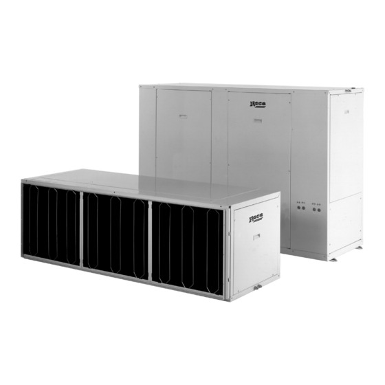
ASAO/ASAI
Air-cooled unitary conditioners
Instructions for Installation, Operation, Maintenance
Autonomes Klimagerät mit Luftkühlung
Hinweise zu, Einbau, Bedienung, Wartung
RETURN TO GENERAL INDEX
ER-028/1/91
CGM-97/013
E U R O V E N T
CERTIFIED PERFORMANCE
Clima Roca York S.L. is participating in the EUROVENT Certification Programme.
Products are as listed in the EUROVENT Directory of Certified Products, in the
AC 1 .
program
Clima Roca York, S.L. ist am Zertifikationsprogramm EUROVENT beteiligt.
Die entsprechend gekennzeichneten Produkte sind im EUROVENT-Jahrbuch im
Programm
GB
AC 1
enthalten.
Ref.: N-21066 0499
1
Advertisement
Table of Contents

Related Manuals for Roca ASAI-25

Summary of Contents for Roca ASAI-25
- Page 1 RETURN TO GENERAL INDEX E U R O V E N T CERTIFIED PERFORMANCE Clima Roca York S.L. is participating in the EUROVENT Certification Programme. Products are as listed in the EUROVENT Directory of Certified Products, in the AC 1 .
-
Page 2: Table Of Contents
Index Inhalt Page Seite Installation instructions Hinweise zum Einbau - General description - Allgemeine Angaben - Protection of the environment - Umweltschutz - Warning signs - Hinweiszeichen - Transport - Transport - Location - Austellung - Clearances - Freiraum - Air ducts - Luftleitungen - Drain connections - Anschluß... -
Page 3: Installation Instructions
Installation instructions General description The ASAO/I model conditioners are supplied in standard form as separate units. They are designed for installation with ducting, on terraces, roof-tops, in lofts and basements. Attention: The unit has a remote control When necessary, and at the moment of installation, these system and can start automatically. -
Page 4: Location
Location should be left for filing the trap with water at the beginning of each season. The location must be chosen providing permanent access for The drain line must have a minimum slope of 2 cm. for each maintenance service, both through the lateral and rear metre of length. - Page 5 5- Unscrew the attachment of the fan to support 5. (ASAI-25, 30, 45) 6- Place panel 3 in the former position of panel 4, and panel 1- Remove the attachment screws from the side panels 1 4 in the former position of panel 3.
- Page 6 ASAI-60 unit ref. 1 to the unit. The ASAI-60 needs a transformation kit which includes: rear 3- Attach the left-hand side angle support and right-hand fan and upper panel, belts, motor pulleys and fan. support ref. 3 to the unit. 1- Dismantle the standard upper, rear and side panels and 4- Change the motor pulleys, fan and belts ref.
-
Page 7: Installation With Separated Units
These will be minimum possible. found in a bag inside the electrical box in the ASAO-60 and Maximum admissible distances with the circuit and standard in the indoor unit in the ASAI-25, 30 & 45. diameter tubes are: Total length Maximum level... -
Page 8: Electrical Installation
Diameter of the interconnection tubing To avoid deterioration through exposure to sunlight it is recommended that it be painted with water-enamel. Liquid Gas line Model line diameter diameter (narrow tube) (wide tube) 1/2" (12.7 mm) ASAO/I-25 en 45 CAUTION " (28.5 mm) ASAO/I-30 en 60 5/8"... -
Page 9: Electrical Characteristics
Electrical characteristics Vermogen A Power supply V.ph.Hz. Power Automatic sup. cable circuit cross Indoor Outdoor Model breaker Compressor section Compressor Start Start Start Nominal Maximum Nominal Nominal Ext. Int. 230.3.50 230.3.50 22.8 34.5 ASAO/I-25 400.3.50 400.3.50 13.2 230.3.50 230.3.50 28.5 ASAO/I-30 400.3.50 400.3.50... -
Page 10: Operating Instructions
Operating instructions Thermostat for ASAO/I-25 & 30 General information Start-up and automatic temperature regulation are carried out through the ambient thermostat. Place the thermostat about 1.5 metres above floor level, where no obstacle can prevent it from measuring the real temperature of the room. -
Page 11: Pressostats
In the OFF position the cooling group does not operate. vacuum cleaner or detergent. When the lever A is in the ON position only the fan functions. In the position COOL or HEAT and AUTO the fan starts up in conjunction with the compressor or electric heater, if fitted CAUTION (as indicated by the thermostat and the room temperatu-... -
Page 12: General Dimensions
General dimensions mm ASAI-25 3/4" G INN. THREAD DRAIN Ø 21 1/2" LIQUID CONNECTION " GAS CONNECTION ELECTRICAL CONNECTIONS ASAO-25 COTOUT PUSH-BUTTONS 3/4" INN. THREAD DRAIN "A" DETAIL Ø 23 Ø 38 ELECTRICAL CONNECTIONS " GAS CONNECTION 1/2" LIQUID CONNECTION... -
Page 13: General Dimensions
General dimensions mm ASAI-30 3/4" G. INN. THREAD DRAIN Ø 21 5/8" LIQUID CONNECTION " GAS CONNECTION ELECTRICAL CONNECTION ASAO-30 CUTOUT PUSH-BUTTONS 3/4" INN. THREAD DRAIN DETALLE "A" Ø 23 Ø 38 ELECTRICAL CONNECTIONS " GAS CONNECTION 5/8" LIQUID CONNECTION "A"... - Page 14 General dimensions mm ASAI-45 3/4" G INN. THREAD DRAIN 1/2" LIQUID CONNECTIONS (2) Ø 21 " GAS CONNECTIONS ELECTRICAL CONNECTIONS ASAO-45 CUTOUT PUSH-BUTTONS 3/4" INN. THREAD DRAIN Ø 23 Ø 38 "A" DETAIL ELECTRICAL CONNECTIONS " GAS CONNECTIONS (2) 1/2" LIQUID CONNECTIONS (2) DETAIL "A"...
- Page 15 General dimensions mm ASAI-60 38 DIAM. ELECTRICAL CONN. (2) 5/8" LIQUID CONNECTION (2) 1 / " GAS CONNECTION 3/4" INN. THREAD DRAIN (ON OPPOSITE SIDE) ASAO-60 38 DIAM. ELECTRICAL CONNECTION 5/8" LIQUID CONNECTIONS (2) " GAS CONNECTION (2) 3/4" INN. THREAD DRAIN (ON BOTH SIDES)
- Page 16 Interconnection diagram ASAO/I-25 & 30, 230.3.50...
- Page 17 Power diagram ASAO/I-25, 230.3.50...
- Page 18 Control diagram ASAO/I-25, 230.3.50 AUTO COOL HEAT INNER ELECTRIC HEATER DUCT ELECTRIC HEATER CRANKCASE OIL HEATER...
- Page 19 Power diagram ASAO/I-30, 230.3.50...
- Page 20 Main diagram ASAO/I-30, 230.3.50 AUTO COOL HEAT INNER ELECTRIC HEATER DUCT ELECTRIC HEATER CRANKCASE OIL HEATER...
- Page 21 Interconnection diagram ASAO/I-25 & 30, 400.3.50...
- Page 22 Power diagram ASAO/I-25, 400.3.50...
- Page 23 Main diagram ASAO-25, 400.3.50 AUTO COOL HEAT INNER ELECTRIC HEATER DUCT ELECTRIC HEATER CRANKCASE OIL HEATER...
- Page 24 Power diagram ASAO/I-30, 400.3.50...
- Page 25 Main diagram ASAO/I-30, 400.3.50 AUTO COOL HEAT INNER ELECT. HEATER DUCT ELECT. HEATER CRANKCASE OIL HEATER...
- Page 26 Interconnection diagram ASAO/I-45, 400.3.50 X2/15 X2/14 X2/S X2/W1 X2/10...
- Page 27 Power diagram ASAO/I-45, 400.3.50...
- Page 28 Main diagram ASAO/I-45, 400.3.50 (1 of 2) AIR FLOW RATE CONTROL INNER ELEC. HEATER CRANKCASE OIL HEATER...
- Page 29 Main diagram ASAO/I-45, 400.3.50 (2 of 2) AUTO COOL HEAT DUCT ELECTRIC HEATER...
- Page 30 Interconnection diagram ASAO/I-60, 400.3.50 24V ROOM THERMOSTAT...
- Page 31 Power diagram ASAO/I-60, 400.3.50...
- Page 32 Main diagram ASAO/I-60 AUTO COOL HEAT CRANKCASE OIL HEATER CRANKCASE OIL HEATER All data subject to change without notice.
- Page 33 DECLARATION OF COMPLIANCE ON MACHINERY KONFORMITÄTSERKLÄRUNG FÜR MASCHINEN MANUFACTURER: CLIMA ROCA YORK, S.L. HERSTELLER: ADDRESSE: Paseo Espronceda, 278, 08.204 SABADELL ANSCHRIFT: This machine complies with the basic demands of the EP Standards on machinery (Standard "EC" 89/392/CEE), including any modification of same.
Need help?
Do you have a question about the ASAI-25 and is the answer not in the manual?
Questions and answers