Table of Contents
Advertisement
Installation, Setup
and Operation
INSTRUCTIONS
for
SUNNEN
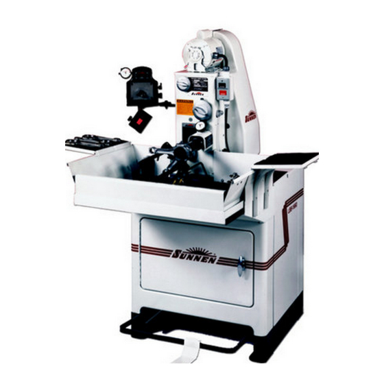
Model LBB-1660
READ THE FOLLOWING INSTRUCTIONS THOROUGHLY AND CAREFULLY BEFORE UNPACKING,
INSPECTING, OR INSTALLING THE SUNNEN
"SUNNEN AND THE SUNNEN LOGO ARE REGISTERED TRADEMARKS OF SUNNEN PRODUCTS COMPANY."
SUNNEN
®
PRODUCTS COMPANY • 7910 MANCHESTER AVENUE • ST. LOUIS, MO 63143, U.S.A. • PHONE: 314-781-2100
®
HONING MACHINE
®
HONING MACHINE.
I-LBB-661H
Advertisement
Table of Contents

Subscribe to Our Youtube Channel
Summary of Contents for Sunnen LBB-1660
- Page 1 READ THE FOLLOWING INSTRUCTIONS THOROUGHLY AND CAREFULLY BEFORE UNPACKING, INSPECTING, OR INSTALLING THE SUNNEN ® HONING MACHINE. “SUNNEN AND THE SUNNEN LOGO ARE REGISTERED TRADEMARKS OF SUNNEN PRODUCTS COMPANY.” SUNNEN ® PRODUCTS COMPANY • 7910 MANCHESTER AVENUE • ST. LOUIS, MO 63143, U.S.A. • PHONE: 314-781-2100...
-
Page 2: General Information
Troubleshooting information can also be found within the Instructions. If you cannot find what you need, call for technical support. Where applicable, programming information for your Sunnen equipment is also included. Most answers can be found in the literature packaged with your equipment. - Page 3 SUNNEN ® SOFTWARE LICENSE AGREEMENT This document is a Legal Agreement between you, as user and licensee (Licensee), and Sunnen ® Products Company (SPC) with respect to preprogrammed software (Software) provided by SPC for use on SPC Equipment. By using the Software, you, as Licensee, agree to become bound by the terms of this Agreement.
-
Page 4: Safety Instructions
35º to 46º C (95º to 115º F). IT IS NOT recommended that Machine, equipped with electronic components, be operated at temperatures above 46º C (115º F). Sunnen Products Company warrants Machine, equipped with electronic components, for operating environments up to 35ºC (95º F). For operating environments of 35º to 46º C (95º to 115º F) the warranty only applies if the optional cooler is installed on Machine, equipped with electronic components. -
Page 5: Table Of Contents
TABLE OF CONTENTS Page TABLE OF CONTENTS ..............v GENERAL INFORMATION &... -
Page 6: General Information & Specifications
HONING MACHINE. Diameters as small as.370 in. (9,4 mm) and as large as 4.700 in. (119 mm) have been honed on the LBB-1660 Honing Machine. The LBB-1660 is a manually stroked honing machine, The operator starts and stops the honing cycle with the pedal while he continuously strokes the workpiece across the full length of the rotating honing stone. - Page 7 152 mm (6 in.) WITH DOOR OPEN 15,9 mm (0.625 in.) DIA. (4 HOLES) 587,4 mm 72 mm 83 mm (23.125 in.) (2.8125 in.) (3.25 in.) OUTLINE LAYOUT Scale: 1 mm = 48 mm 1/4 in. = 1 ft. 813 mm (32 in.) FRONT 1250 mm...
- Page 8 NOTES viii...
-
Page 9: Installation
If damage is evident, immediately file a inspecting, and installing Sunnen ® Honing Machine, claim with carrier. model LBB-1660. Hereafter, referred to as Machine (see Figure 1-1). 4. Place Machine in desired location. TOOLS & MATERIALS 5. Level Machine in both left to right and front to The following tools and materials are required for back directions. -
Page 10: Foot Pedal
FOOT PEDAL The following instructions cover installation of Foot Pedal Assembly on Sunnen Pedestal Honing Machines. To install Foot Pedal Assembly, proceed as follows (see Figure 1-3): DO NOT attempt to fork machine with NOTE: Pedal Tube Assembly and Pedal Assembly installed. -
Page 11: Coolant Reservoir
COOLANT Fill Coolant Reservoir with Sunnen Honing Oil or Water-Based Coolant as follows (see Figure 1-5): DISCONNECT NOTE: Maximum capacity of Reservoir is 19 BLOCK gallons (72 liters) without filter; or 22 gallons (83 liters) with filter. Minimum capacity of 8 gallons (30 liters ) is needed for proper pump operation. - Page 12 9. Close Total Volume and Individual Control Valves on Flow Control Manifold. Total Volume Valve may now be used to NOTE: shut entire supply off, leaving individual settings unchanged. SPINDLE DRIVE MOTOR CONTROLS GAGE (Optional) BELT GUARD WORK TRAY DISCONNECT SWITCH (Optional) WORK TRAY...
-
Page 13: Preparing For Operation
SECTION 2 PREPARING FOR OPERATION GENERAL motor, stroking drive motor, and expands stones. Assembly consist of following components: Consult this section when preparing Machine for operation. Adjustable Pedal Bar & Pedal is located on lower front of machine. Both Bar and Pedal are adjustable MAJOR COMPONENTS to accommodate individual operator. - Page 14 Clean Coolant spills. Coolant can be slick and can FIGURE 2-5, Electrical Components provide a personal fall hazard. 6. ELECTRICAL COMPONENTS Sunnen Honing Machine is available in 110/230 Volt, single phase, 60 Hz.; or 220//380/440 Volt, 50 Hz, 3 Phase. Its...
-
Page 15: Safety Symbols
For a description of safety symbols used on this Gage Mount, Model MB-2370A. Mounts on left machine, refer to Table 2-1. front of machine and is used to rest Sunnen AG/PG MACHINE CONTROLS Gage on for easy access during honing. For location and function of machine controls refer to Figure 2-6 and Table 2-2. -
Page 16: Setup
(½ to 1) Volume Control Valve fully clockwise. 1.000 UP 25,4 UP 3. Select Honing Unit from Sunnen Engine Rebuilding Equipment Accessories & Supplies Catalog (A-7100). Depending on your part configuration, select a honing unit type and size most suitable. - Page 17 12. Test Wedge hookup by pulling Honing Unit straight out; if Wedge comes out repeat steps 9 thru 12. If wedge is hooked up, it will not allow unit to come out of spindle. LARGE SETSCREW 13. Push unit back into Spindle Nose until it bottoms. 14.
- Page 18 31. Press START Button. VALVES CAUTION COOLANT NOZZLE Use only undiluted Sunnen Industrial Honing Oil. This oil will ensure free cutting, reliable stone performance, and consistent surface finish. 32. Attach and adjust position of Coolant Nozzles (see Figure 2-14). Coolant should contact front and rear of Stone, parallel to mandrel.
- Page 19 47. Advance Feed Dial four (4) numbers; Depress TABLE 2-4, Cutting Pressure Setting Pedal and continue honing until Honing Dial Needle BORE SIZE PRESSURE CONTROL reaches "0"; then release Pedal. inches millimeters INITIAL SETTING .375 to .500 9,5 to 12,7 to ½) CAUTION .500 to 1.000...
-
Page 20: Manual Stroke Honing
Position Work Support as close as possible to end of Rod without locating on curved portion of rod. CAUTION All workpieces MUST be in a Holding Fixture to avoid injury and damage to machine (see Sunnen Data Files 107 and 108 for fixturing suggestions). -
Page 21: Setup & Operation
SECTION 3 SETUP & OPERATION GENERAL vent personal injury and machine damage, DO NOT hone without installing part in workholding fixture. This section describes a step-by-step operating • To avoid personal injury, allow spindle and stroking procedure for Machine. arm to come to a complete stop before removing part. •... - Page 22 Honing: Always start and stop stroking in middle of stone. Use Sunnen "CR" type hone unit. Set Heavy Cutting Pressure Dial to "0". For rough honing set Light Cutting Pressure Dial between "2-1/2 to 3-1/2";...
-
Page 23: Operation
KL-, 1PL-, RL- Pin fitting in con rods and cylinder 5. Gage hole size, using Sunnen Hole Gage, to reconditioning in small bore engines. determine amount of stock to be removed. Refer to 3ML-, 4ML-, 5ML-, 4PL-, 5PL-, UL- Kin pin fitting. - Page 24 NOT estimate how much stone stone (see Sunnen Trouble-shooting Guide on next feed-up is needed. Generally it is better to hone part page). Excessive pressure can cause unnecessary until Honing Dial reads "0", gage hole, advance...
-
Page 25: Routine Maintenance
SECTION 4 ROUTINE MAINTENANCE GENERAL LUBRICATION The following procedures and suggested maintenance Hand lubricate various machine components called periods are given as guides only and are not to be out in Figure 4-1, according to suggested intervals construed as absolute or invariable. Local conditions called out in Table 4-1. -
Page 26: Coolant Level Check
(refer to Appendix Replace Coolant using ONLY Sunnen Industrial Honing Oil or Sunnen Water-Based Coolant. If the machine is low on coolant, order more Sunnen Industrial Honing Oil. Do Not add CLAMP DRAIN PIPE kerosene, cutting fluids, or any other fluids to KNOB coolant that is left - it will ruin coolant. -
Page 27: Feed Dial
25. Re-install belt and adjust for proper tension. ting action. To adjust go to step 4. 26. Pump Sunnen Honing Oil or Sunnen Water- With needle set on red line, you hone a part to zero Based Coolant into Coolant Reservoir or pour into under full load. -
Page 28: Cutting Pressure Controls
5. If needle is not on red line, loosen cap screw on side of honing dial bracket and slide Honing Dial up as far as it will go. Then move it down so that needle makes one full turn. Continue moving indicator down until needle is on red line. - Page 29 honing dial needle should stop between 4 and 5. If it doesn't, loosen locknut C and repeat step 18. LOCKNUT 21. Make sure both pressure controls are turned all the way counterclockwise against stops (to zero). 22. Push Feed Dial in as far as you can and release slowly.
-
Page 30: Coolant System
FIGURE 4-10, Pump (see Figure 4-10). NOTE: If the machine is low on oil, order more Sunnen Industrial Honing Oil. DO NOT ADD SCREW KEROSENE, CUTTING FLUIDS, OR ANY OTHER FLUID TO THE OIL THAT'S LEFT - IT BELT WILL BE RUINED. If you must operate the machine before you receive your new oil, temporarily drain and remove Sediment Tray. -
Page 31: Pedal Adjustment (Ce)
WARNING Turn electrical power OFF at main buss box or PUMP BELT main power source when performing any LOWER CONE maintenance not requiring power. PULLEY COVER 1. Turn OFF all electrical power to machine. PLATE FEED SCREW 2. Loosen safety latch pin, raise belt cover latch PROJECTION and open belt guard. -
Page 32: Replace Spindle Drive Belt
REPLACE SPINDLE DRIVE BELT To inspect and replace Flat Spindle Drive Belt, proceed as follows (see Figure 4-15): WARNING Turn electrical power OFF at main buss box or main power source when performing any maintenance not requiring power. 1. Turn OFF all electrical power to machine. 2. -
Page 33: Adjust Brake Strap
9. Recheck Brake Strap Tension Adjustment after 10 hours of operation and readjust as required. SCREW REPLACE BRAKE STRAP BRAKE To replacement worn or broken Brake Strap proceed LEVER as follows (refer to Figures 4-18 & 19): BRAKE BRAKE WARNING ANCHOR STUD Turn electrical power OFF at main buss box or... - Page 34 NOTES...
-
Page 35: Troubleshooting
*NOTE: Many honing problems, such as poor stone life, and rough finish, are caused by wrong coolant; insufficient coolant, dirty coolant, or contaminated coolant. Use ONLY clean, Sunnen Industrial Honing Oils or Water-Based Coolant. Make sure that coolant is neither diluted nor "cut" with other coolants. Keep solvents and cleaning fluids away from... - Page 36 *NOTE: Many honing problems, such as poor stone life, and rough finish, are caused by wrong coolant; insufficient coolant, dirty coolant, or contaminated coolant. Use ONLY clean, Sunnen Industrial Honing Oils or Water-Based Coolant. Make sure that coolant is neither diluted nor "cut" with other coolants. Keep solvents and cleaning fluids away from...
-
Page 37: A Checklist Setup & Operation Sequence
APPENDIX A CHECKLIST SETUP & OPERATION SEQUENCE SETUP - GENERAL (Section 2) WARNING 1. Press STOP Switch. An Arc Flash Hazard Exists. Follow safe 2. Turn OFF oil supply. work practices and wear appropriate 3. Select Stone. Personal Protective Equipment. Follow 4. - Page 38 NOTES...
-
Page 39: Appendixes
APPENDIX... - Page 40 NOTES...
-
Page 41: C Diameter Range Of Mandrels & Honing Units
APPENDIX C DIAMETER RANGES MANDRELS & HONING UNITS CAUTION: DO NOT ORDER FROM THIS PAGE. See Sunnen ® Engine Rebuilding Equipment Accessories And Supplies Catalog (A-7100) for complete ordering information. King Pin Fitting Fitting Pins in Pistons SIZE RANGE SIZE RANGE... - Page 42 APPENDIX C DO NOT ORDER FROM THIS PAGE. See Sunnen Engine Rebuilding Equipment Accessories CAUTION: ® And Supplies Catalog (A-7100) for complete ordering information. RECONDITIONING CON-RODS FITTING PINS IN CON-RODS SIZE RANGE SIZE RANGE MANDREL inches millimeters MANDREL inches millimeters CR-1450 1.450 to 1.600...
-
Page 43: D Coolant Flow Diagram
APPENDIX D COOLANT FLOW DIAGRAM CLAMP KNOB PUMP PUMP BRACKET SCREEN CHECK VALVE MANIFOLD TRAY PUMP MACHINE RESERVOIR DIRTY OIL DIRTY OIL FIGURE D-1, Coolant Flow Diagram... - Page 44 NOTES...
-
Page 45: E Declaration Of Conformity (Ce)
APPENDIX E DECLARATION OF CONFORMITY (CE) (PAGE 1 OF 2) - Page 46 APPENDIX E DECLARATION OF CONFORMITY (CE) (PAGE 2 OF 2)
- Page 47 Like any machinery, this equipment may be dangerous if used improperly. Be sure to read and follow instructions for operation of equipment. WARNING An Arc Flash Hazard Exists. Follow safe work practices and wear appropriate Personal Protective Equipment. Follow proper lockout/tagout procedures. Failure to comply can result in death or injury.
- Page 48 METERS (m) METERS (m) 3.281 FEET (ft) – S “SUNNEN ® AND THE SUNNEN LOGO ARE REGISTERED TRADEMARKS OF SUNNEN PRODUCTS COMPANY.” WITZERLAND UNNEN Phone: ++ 41 71 649 33 33 Fax: ++ 41 71 649 34 34 www.sunnen.ch e-mail: info@sunnen.ch S.R.L.
Need help?
Do you have a question about the LBB-1660 and is the answer not in the manual?
Questions and answers