Table of Contents
Advertisement
Quick Links
Table of Contents
1
Introduction ..................................................................................................................... 3
1.1
1.2
1.3
1.4
2
Safety Information........................................................................................................... 8
2.1
2.2
2.3
2.4
2.5
2.6
2.7
2.8
2.9
2.10
3
Product Description....................................................................................................... 20
3.1
3.2
3.3
3.4
3.5
4
Functions and Parameters of the Vivo 40 ..................................................................... 27
4.1
4.2
4.3
4.4
4.5
4.6
4.7
4.8
4.9
4.10
4.11
5
Using the Vivo 40 .......................................................................................................... 35
5.1
5.2
5.3
5.4
5.5
5.6
5.7
5.8
6
Preparing the Vivo 40 for Use ....................................................................................... 53
Doc. 003886 En-Us A-1ei
What is the Vivo 40? ......................................................................................... 4
Intended Use..................................................................................................... 4
Contraindications .............................................................................................. 5
.......................................................................................... 6
General User Precautions ............................................................................... 8
Electrical Safety ............................................................................................ 10
Environmental Conditions ............................................................................. 11
Invasive Use ................................................................................................... 14
Usage of Filters ............................................................................................... 15
Humidification ............................................................................................... 16
Cleaning and Maintenance ............................................................................. 17
Adverse Patient Symptoms............................................................................. 18
Usage of Oxygen .......................................................................................... 19
Main Components ........................................................................................... 20
........................................................................................ 22
Ventilation Mode.............................................................................................. 27
Device Mode ................................................................................................... 27
Settings ........................................................................................................... 27
The PCV Mode (Pressure Control Ventilation)................................................ 30
The PSV Mode (Pressure Support Ventilation)............................................... 31
The Difference between PCV and PSV Mode ................................................ 32
Target Volume ................................................................................................. 33
The CPAP Mode ............................................................................................. 33
Standby and Operating Mode ......................................................................... 34
Low Leakage Detection................................................................................... 34
Humidifier (optional) ........................................................................................ 34
Set up the Vivo 40 Before Use........................................................................ 35
Switching the Vivo 40 On and Off ................................................................... 36
Using the Menu ............................................................................................... 37
Monitoring Section .......................................................................................... 43
Transferring Data between the Vivo 40 and a PC ......................................... 44
Using Batteries................................................................................................ 49
Vivo 40 Operating Time................................................................................... 52
............................................................................... 12
......................................................................... 24
........................................................... 25
.................................................. 26
....................................................................... 48
BREAS Vivo 40 clinician's manual
Table of Contents
1
Advertisement
Table of Contents

Related Manuals for Breas Vivo 40


Summary of Contents for Breas Vivo 40
-
Page 1: Table Of Contents
Set up the Vivo 40 Before Use................ 35 Switching the Vivo 40 On and Off ..............36 Using the Menu ....................37 Monitoring Section ..................43 Transferring Data between the Vivo 40 and a PC ......... 44 Using the HA 01 Humidifier ............... 48 Using Batteries....................49 Vivo 40 Operating Time................... - Page 2 Installing the Vivo 40 ..................53 Placing the Vivo 40 ..................54 Connecting the Vivo 40 to the AC Power Source .......... 54 Connecting the Patient Circuit................. 56 Setting Up the Vivo 40 ....................58 Settings Applicable for the Different Modes ........... 59 Selecting the Mode ..................
-
Page 3: Introduction
WARNING! Do not use the Vivo 40 for any kind of total ventilatory requirement. Breas Medical AB reserves the right to make changes to this product without any prior notification. -
Page 4: What Is The Vivo 40
The internal memory of the Vivo 40 can be downloaded to a PC where you can view the patient compliance data in the Breas Vivo PC Software. -
Page 5: Contraindications
The Vivo 40 is intended to be operated by qualified and trained personnel. The Vivo 40 is intended for use in clinical settings (e.g., hospitals, sleep labora- tories, sub-acute care institutions) and home environments. The Vivo 40 must always be prescribed by a licensed physician. -
Page 6: About This Manual
The manual comprises detailed information on the settings and functions of the Vivo 40 to be handled by trained health care personnel only. • Patients and other lay users operating the Vivo 40 will find all the informa- tion they need in the User Manual. - Page 7 Note Information that may be valuable but is not of critical impor- tance, tips. Reference Reference to other manuals with additional information on a specific topic. Introduction Vivo 40 clinician’s manual Doc. 003886 En-Us A-1e...
-
Page 8: Safety Information
Safety Information 2.1 General User Precautions • The Vivo 40 must be switched off and on at least once a day. This is neces- sary in order for the Vivo 40 to perform a self test. • U.S. Federal law restricts this device for sale by or on order of a physician. - Page 9 Start/Stop button is pressed even without the AC power being connected. • Do not use the Vivo 40 while in a carry bag. Attach the rear lid and place the swivel in a down position when placing the Vivo 40 in the bag.
-
Page 10: Electrical Safety
HA 01 humidifier will be turned off automatically. It must be activated again manually, if humidification during battery use is necessary. • Only use the data connection to connect the Vivo 40 to the iCom or a PC. 10 Safety Information Vivo 40 clinician’s manual... -
Page 11: Environmental Conditions
• Do not use the Vivo 40 in environments where there are explosive gases or other flammable anesthetic agents present. • The air flow for breathing produced by the Vivo 40 can be as much as 10°F (5°C) higher than room temperature. Caution should be exercised if the room temperature is greater that 95°F (35°C). -
Page 12: Usage Of Patient Circuit
• Do not use patient hoses or tubes made of static or electrically conductive material. • Always use a new mask, tube and leakage port when the Vivo 40 is to be used by a new patient. • Patient connected parts and filter must be replaced regularly to ensure cor- rect function of the Vivo 40. - Page 13 • Do not leave long lengths of air tubing around the top of the bed. It could twist around the patient’s head or neck while sleeping. • Always follow the instructions of the mask manufacturer. Safety Information Vivo 40 clinician’s manual Doc. 003886 En-Us A-1e...
-
Page 14: Invasive Use
• The Vivo 40 is equipped with a low leakage alarm. The low leakage alarm is not a substitute for operator vigilance in ensuring that the leakage ports remains clear at all times. -
Page 15: Usage Of Filters
• When operating the Vivo 40, make sure that the air inlet and filters are not obstructed or occluded. • If the Vivo 40 is used in a clinic by several patients, a low resistance bacteria filter is recommended between the air outlet and the patient circuit to pre- vent patient cross-contamination. -
Page 16: Humidification
• The HA 01 humidifier is intended for non-invasive use only. • Do not place the Vivo 40 with the HA 01 humidifier in a bag. • When the HA 01 humidifier is installed, the Vivo 40 must be located below the patient and on a flat surface. -
Page 17: Cleaning And Maintenance
• Vivo 40 should be subjected to maintenance, service and control and any applicable upgrades, in accordance with Breas service instructions. • Vivo 40 shall only be repaired or modified in accordance with Breas service manuals, technical bulletins, and any special service instructions, by service technicians authorized by Breas Medical AB. -
Page 18: Adverse Patient Symptoms
2.9 Adverse Patient Symptoms If the patient experiences discomfort or any of the following symptoms while using the Vivo 40, a physician or responsible clinician shall be contacted immediately: • Bloated feeling from excessive swallowing of air while awake • Air continually leaking from the mouth while sleeping •... -
Page 19: Usage Of Oxygen
• Do not use aerosols or solvents close to the oxygen supply, even when the oxygen supply is shut off. • When the Vivo 40 is not in operation, and the oxygen flow is left on, oxy- gen delivered into the patient tubing may accumulate within the machine enclosure. -
Page 20: Product Description
Product Description 3.1 Main Components The Vivo 40 system contains the following components: 20 Product Description Vivo 40 clinician’s manual Doc. 003886 En-Us A-1e... - Page 21 003522 Filter (white, disposa- Inlet air filtration 003526 ble) Filter (grey, washable) Inlet air filtration 003527 Rear lid For usage without 003591 the HA 01 humidifier Vivo 40 main unit Product Description Vivo 40 clinician’s manual Doc. 003886 En-Us A-1e...
-
Page 22: Accessories
OMPONENT UNCTION ART NO HA 01 Humidifier Humidifies patient air 003530 Trach elbow Trach connection 004810 Hygroscopic Con- Humidifier 003974 denser Humidifier (HCH) Leakage/Exhalation Providing a leakage 004426 port 22 Product Description Vivo 40 clinician’s manual Doc. 003886 En-Us A-1e... - Page 23 • Vivo-iCom data cable • iCom-PC data cable (D-sub) • iCom-PC data cable (USB) • iCom User manual • iCom PC drivers Vivo-PC data cable Data cable: PC and Vivo 40 003588 (RJ45 to D-sub) Vivo-iCom Data cable: Vivo 40 and iCom 003574...
-
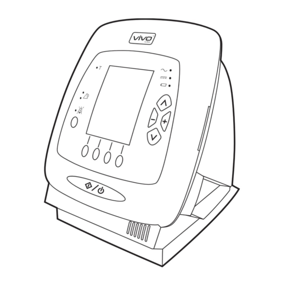
Page 24: The Vivo 40'S Front Panel
3.3 The Vivo 40’s Front Panel 7, 8, 9, 10 UTTONS UNCTION Start/Stop Start/Stop ventilation treatment Audio pause Pause the alarm sound 7-10 Function/Navigation Function according to display 14-17 Navigation/Setting Navigation in current menu selection/ Define settings UNCTION Trigger Patient breath trigger indication Alarm (red &... -
Page 25: The Vivo 40'S Back And Side Panels
3.4 The Vivo 40's Back and Side Panels UNCTION Air inlet Air path in, replaceable filters Locking mechanism Release and lock the HA 01 humidifier or rear lid Air outlet Air path out to the patient Memory card slot Read and write memory card... -
Page 26: Equipment Designation And Safety Label
Data connection port (for iCom or PC) Before using the data connection port, read “Transferring Data between the Vivo 40 and a PC” on page 44 carefully. Class II electrical equipment; double insulation Body floating (IEC 60601-1 Type BF, Isolated Applied Part) Read the clinician’s manual thoroughly before... -
Page 27: Functions And Parameters Of The Vivo 40
• Home In order to prevent the patient from changing the settings, the home mode should be activated before giving the Vivo 40 to the user. The home mode hides treatment settings, alarm limits and other selected information. The clinical mode is used by the clinician to control all mode choices, settings and limits. - Page 28 Breath Rate (PSV & PCV only, mandatory) The breath rate defines the minimum number of breaths the Vivo 40 will deliver. If the number of spontaneous patient breaths per minute is less than this number, Vivo 40 will uphold this rate.
- Page 29 Time During CPAP mode the ramp function provides a pressure increase from the ramp start pressure to the set CPAP pressure during a set time. Functions and Parameters of the Vivo 40 Vivo 40 clinician’s manual Doc. 003886 En-Us A-1e...
-
Page 30: The Pcv Mode (Pressure Control Ventilation)
4.4 The PCV Mode (Pressure Control Ventilation) In the PCV mode, the ventilation is controlled by the Vivo 40. This is done by the pressure, rate, inspiration time, and rise time settings. Inspiration is started either when the ventilator initiates a breath, or when the patient triggers a breath (if the trigger function is activated). -
Page 31: The Psv Mode (Pressure Support Ventilation)
EPAP seconds Insp. time PSV Flow Max. flow Flow has dropped Exp. Trig. to set Exp. Trig. setting seconds New breath Patient is triggered exhales Functions and Parameters of the Vivo 40 Vivo 40 clinician’s manual Doc. 003886 En-Us A-1e... -
Page 32: The Difference Between Pcv And Psv Mode
The figure below shows the previous two examples superimposed to illustrate how the PCV and PSV modes differ. Pressure IPAP EPAP seconds Insp. time PSV Insp. time PCV Flow seconds 32 Functions and Parameters of the Vivo 40 Vivo 40 clinician’s manual Doc. 003886 En-Us A-1e... -
Page 33: Target Volume
Target volume is a feature that automatically adapts the IPAP to make sure that the Vivo 40 delivers the desired set tidal volume to the patient. The delivered volume is calculated and compared to the set target volume on a breath by breath basis. -
Page 34: Standby And Operating Mode
4.9 Standby and Operating Mode Standby mode is defined as the state of the Vivo 40 when AC power is con- nected and the On/Off switch is on, but without starting the Vivo 40 with the Start/Stop button. Operating mode is defined as the state of the Vivo 40 when the fan is operating and producing an air flow. -
Page 35: Using The Vivo 40
Press the Start/Stop button on the front panel. Check that a short sound signal is heard. If there is no signal, do not use the Vivo 40 and contact your service provider. Ensure that the settings are adjusted as prescribed. -
Page 36: Switching The Vivo 40 On And Off
5.2 Switching the Vivo 40 On and Off Switching On Make sure the AC power source is connected and the On/Off switch is switched on. Turn on the Vivo 40 by pressing the Start/Stop button on the front panel for 2 seconds. Press for 4 sec- onds when using an external or inter- nal battery. -
Page 37: Using The Menu
“+” and “-” buttons on the front panel to navigate the Vivo 40 menu. Read chapter “The Vivo 40’s Front Panel” on page 24 for exact position of the buttons. The navigation buttons are used to view the different sections defined above each navigation button. - Page 38 On, Off Panel locked by the Breas On, Off Vivo PC software Rise time 1 to 9 Inspiratory trigger 1 to 9, Off Expiratory trigger 1 to 9 38 Using the Vivo 40 Vivo 40 clinician’s manual Doc. 003886 En-Us A-1e...
- Page 39 Overview The Vivo 40 menu has the following section layout in the clinic mode: Alarm Limits Mode Basic Setup Others Alarm History More Settings Humidity (if used) Ramp CPAP Wake Up Alarm Adjust Adjust Adjust Device Settings Parameters Parameters Parameters...
- Page 40 “Wake up Alarm” to reach the “Wake up Alarm” page. Device Settings Navigate to the section “Others” and select “Device Settings” to reach the “Device Settings” page. 40 Using the Vivo 40 Vivo 40 clinician’s manual Doc. 003886 En-Us A-1e...
- Page 41 Switching between Clinical and Home Mode Navigate to the “Mode” section. Use the down arrow to navigate to the “Device Mode” setting. Select the required mode with the “+” and “-” buttons. Using the Vivo 40 Vivo 40 clinician’s manual Doc. 003886 En-Us A-1e...
- Page 42 Vivo 40 enters the home mode. It cannot be switched back to clinical mode by using the menu. The Vivo 40 is unlocked from the home mode by pressing the “+” and “-” but- tons again simultaneously for 5 seconds.
-
Page 43: Monitoring Section
Settings in Home Mode To show settings in home mode: Enter the main screen and press up button for 3 seconds. Using the Vivo 40 Vivo 40 clinician’s manual Doc. 003886 En-Us A-1e... -
Page 44: Transferring Data Between The Vivo 40 And A Pc
In order to view and present patient data correctly, the Breas Vivo PC Software must be installed on the PC. Instructions on how to manage data in the Breas Vivo PC Software can be found in the software help. Data can be transferred in three ways: •... - Page 45 Memory Card The Vivo 40 can only copy and transfer data to the memory card in standby mode (not operating). The memory card is used for copying and transferring settings, detail logs, usage logs and breath logs. Insert the memory card in the memory card slot on the side of the Vivo 40.
- Page 46 Vivo-PC data cable to the PC. iCom Communication Unit The iCom is an accessory which electrically isolates the Vivo 40 from a PC and other devices (i.e. plotters, printers etc). A common PC, which does not comply with IEC 60601-1, must comply with IEC 60950 and be placed outside the patient area (i.e.
- Page 47 Connect the Vivo-iCom data cable to the Vivo 40. Make sure it is fitted correctly. Connect the other end of the Vivo-iCom data cable to the iCom. Connect the iCom-PC data cable between the iCom and a PC. Do only use either the D-sub cable or the USB cable.
-
Page 48: Using The Ha 01 Humidifier
HA 01 humidifier must be installed in order to access and navigate to the humidifier setting on the Vivo 40 menu, both in clinical and home mode. The HA 01 humidifier can only be activated if the Vivo 40 is operating. -
Page 49: Using Batteries
AC power External DC Internal battery When a power source fails, the Vivo 40 will switch to either the internal or the external battery if installed and show a message in the display window. When running on battery, the bat-... - Page 50 • Exercise the battery every 3 months by discharging it completely and fully recharging it again. Repeat this procedure twice. • If the Vivo 40 is stored for more than 1 month, connect it to the AC power supply to recharge the internal battery and alarm battery.
- Page 51 Sea level External Battery The Vivo 40 can be operated from a 12 V or a 24 V DC external battery. • Use the battery cable 12/24 V DC and check carefully that the voltage is 12 V or 24 V.
-
Page 52: Vivo 40 Operating Time
Connect the other end of the cable to the battery source. • Only use a Breas external DC cable to connect the Vivo 40 to the external battery. • An external battery must be disconnected when the Vivo 40 is switched off, otherwise the battery can be discharged. -
Page 53: Preparing The Vivo 40 For Use
Ensure that the equipment is in good condition. If stored more than 1 month, connect the Vivo 40 to the AC power supply and switch on the On/Off switch to recharge the internal battery and the alarm battery in standby mode. -
Page 54: Placing The Vivo 40
Make sure that nothing can block the patient air inlet at the rear of the Vivo 40. 6.3 Connecting the Vivo 40 to the AC Power Source Read the chapter “Electrical Safety” on page 10 carefully to make sure all conditions are fulfilled and considered. - Page 55 Connect the power cord to the AC power source. Preparing the Vivo 40 for Use Vivo 40 clinician’s manual Doc. 003886 En-Us A-1e...
-
Page 56: Connecting The Patient Circuit
Connect the other end of the patient tube to the leakage port, a hygro- scopic condenser humidifier (HCH) and a trach elbow. Intentional Leakage 56 Preparing the Vivo 40 for Use Vivo 40 clinician’s manual Doc. 003886 En-Us A-1e... - Page 57 20 to 40 liter/min at 10 cmH O pressure. This leakage may be achieved by: • integrated leakage in the mask • an adjoining leakage port Preparing the Vivo 40 for Use Vivo 40 clinician’s manual Doc. 003886 En-Us A-1e...
-
Page 58: Setting Up The Vivo 40
Read the chapter “Safety Information” on page 8 before setting up and using the Vivo 40. The configuration of the Vivo 40 therapy settings must always be pre- scribed by a licensed physician and carried out by an authorized health care professional. -
Page 59: Settings Applicable For The Different Modes
HA 01 humidifier 1 to 9, Off The ventilation modes and setting parameters are described in detail in the chapter “Functions and Parameters of the Vivo 40” on page 27. Setting Up the Vivo 40 Vivo 40 clinician’s manual Doc. 003886 En-Us A-1e... -
Page 60: Selecting The Mode
The ventilator always starts in the mode and with the settings that were active when it was switched off. 60 Setting Up the Vivo 40 Vivo 40 clinician’s manual Doc. 003886 En-Us A-1e... -
Page 61: Setting The Parameters
7.3 Setting the Parameters If the set values are outside the Vivo 40’s working range and cannot be achieved, the lines for these settings will flash. Adjust the settings so that the flashing ceases. For more information about how to use the menu, please read the chapter “Using the Menu”... - Page 62 Setting range: 1 to 9, Off (where 1 is the most sensitive). Navigate to the section “Setup” and press “Setup” one more time to reach the “More Settings” page. 62 Setting Up the Vivo 40 Vivo 40 clinician’s manual Doc. 003886 En-Us A-1e...
- Page 63 IPAPmax (PSV & PCV only, Target Volume active) Setting range: 4 or IPAPmin to 40 cmH Navigate to the section “Setup” and press “Setup” one more time to reach the “More Settings” page. Setting Up the Vivo 40 Vivo 40 clinician’s manual Doc. 003886 En-Us A-1e...
- Page 64 Navigate to the section “Others” and select “Ramp” to reach the “Ramp” page. In home mode the ramp can be activated by pressing the ramp soft key for more than 1 second. 64 Setting Up the Vivo 40 Vivo 40 clinician’s manual Doc. 003886 En-Us A-1e...
- Page 65 “Humidity” to reach the “Humidity” page. In home mode the HA 01 humidifier can be activated by pressing the humidity soft key for more than 1 second. Setting Up the Vivo 40 Vivo 40 clinician’s manual Doc. 003886 En-Us A-1e...
-
Page 66: Alarms
8.1 Alarm Function The alarm function of the Vivo 40 consists of the alarm LEDs on the front panel, an audible alarm, and messages on the LCD display (see “The Vivo 40’s Front Panel”... - Page 67 An alarm will automatically be reset once the cause of the alarm has been cor- rected. If an alarm condition cannot be corrected, discontinue use and refer the Vivo 40 for service. Alarms Vivo 40 clinician’s manual Doc. 003886 En-Us A-1e...
- Page 68 The latest alarm will be placed in top of the list. The Alarm History is maintained when the Vivo 40 is powered down. The last set alarm settings are retrieved after power has been off.
-
Page 69: Physiological Alarm
Resolution: 2 cmH IPAP/IPAP- 1.0 cmH Ventilator action The Vivo 40 will continue to give breaths with the same settings. Indication The alarm is given audibly with a tone and visibly by the red alarm LED and a display message. - Page 70 Setting Self adjusting Ventilator action The Vivo 40 will terminate inspiration from the first high pressure breath. The Vivo 40 will then continue to give breaths with same settings. Indication The alarm is given audibly and visibly by the red alarm LED and a display message.
- Page 71 Resolution: 0.03 l 2.0 l 0.05 l Ventilator action The Vivo 40 will continue to give breaths with the same settings. Indication The alarm is given audibly with a tone and visibly by the red alarm LED and a display message.
- Page 72 Resolution: 4 BPM 50 BPM 1 BPM Ventilator action The Vivo 40 will continue to give breaths with the same settings. Indication The alarm is given audibly with a tone and visibly by the yellow alarm LED and a display message.
- Page 73 Resolution: 10 BPM 60 BPM, Off 1 BPM Ventilator action The Vivo 40 will continue to give breaths with the same settings. Indication The alarm is given audibly with a tone and visibly by the yellow alarm LED and a display message.
- Page 74 • Incorrect patient circuit leakage. • Obstructed or occluded patient circuit. Setting Self adjusting Ventilator action The Vivo 40 tries to continue delivering breaths according to settings. Indication The alarm is given audibly with a tone and visibly by the yellow alarm LED and a display message.
- Page 75 • Leakage in patient circuit. • The patient has removed the mask. Setting Self adjusting Ventilator action The Vivo 40 tries to continue delivering breaths according to settings. Indication The alarm is given audibly with a tone and visibly by the red alarm LED and a display message.
-
Page 76: Technical Alarm
If this should happen, restart the Vivo 40 on internal battery. If the low bat- tery alarm persists, the internal battery needs to be charged. - Page 77 Discharged batteries. Alarm limits Internal battery: 14 ±0.75 V Ventilator action The Vivo 40 stops giving breaths and gives alarm for 2 minutes. Indication The alarm is given audibly with a tone and visibly by the red alarm LED and a display message.
- Page 78 Definition An internal function failure alarm will be given when the Vivo 40 has an internal function failure. Ventilator action The Vivo 40 will continue or stop the treatment depending on the type and priority of the alarm. Indication The alarm is given audibly with a tone and visible by a display message at least for 120 seconds.
-
Page 79: Complete Function Check
• Check that the cables are properly connected. Inspection of placement • The Vivo 40 shall be placed on solid flat surface below the patient level. • Make sure that nothing can block the patient air inlet at the rear. -
Page 80: Alarm Check
9.2 Alarm Check If an alarm check fails, do not use the Vivo 40 and contact your responsi- ble service provider for an inspection of the device. Chapter “Alarms” on page 66 has a detailed description of the alarm functions used for the Vivo 40. - Page 81 Connect a patient circuit to the Vivo 40. Enter operating mode by starting the treatment. Create pressure towards the Vivo 40 by blowing air into the mask or patient tube. The high pressure alarm shall be activated after 3 consecutive high pressure breaths.
- Page 82 Check the Switching of Power Source to the Internal Battery Disconnect the power cord from the AC power supply. Treatment continues and the Vivo 40 runs on internal battery with the internal battery LED lit. Reconnect the power cord to the AC power supply.
-
Page 83: Cleaning The Vivo 40 And Replacement Of Accessories
Accessories The patient-connected parts and the filter must be cleaned and replaced regu- larly to ensure correct function of the Vivo 40. All replaced parts must be dis- posed of in accordance with local environmental regulations regarding the disposal of used equipment and waste. - Page 84 The patient circuit should always be cleaned, disinfected and replaced in accordance with the applicable manufacturer’s instructions. Always replace the patient circuit with a new one when the Vivo 40 is to be used by a new patient. 84 Cleaning the Vivo 40 and Replacement of Accessories Vivo 40 clinician’s manual...
-
Page 85: Cleaning And Replacing The Patient Air Filters
Wash the filter using warm water and a mild soap. Rinse thoroughly. Dry the filter by squeezing it out in a towel. Do not wring the filter. Cleaning the Vivo 40 and Replacement of Accessories Vivo 40 clinician’s manual Doc. 003886 En-Us A-1e... -
Page 86: Change Of Patient
Do not wash or reuse the disposable filter. 10.3 Change of Patient If the Vivo 40 is used in a clinic by several patients, a low resistance bacteria fil- ter may be used between the air outlet and the patient tube to prevent patient cross-contamination. -
Page 87: Maintenance
• Do not under any circumstances attempt to service or repair the Vivo 40 yourself. If you do so, the manufacturer will no longer be responsible for the performance and safety of the Vivo 40. EVIATION FROM THESE SERVICE INSTRUCTIONS MAY LEAD TO RISK OF PERSONAL INJURY 11.1 Regular Maintenance Control... -
Page 88: Service And Repair
11.2 Service and Repair The service and repair of the Vivo 40 must be carried out by authorized service personnel in accordance with Breas service instructions. Service inspections must always be carried out after any repair of the device. Authorized service workshops can order the Vivo 40 Service Manual that con- tains all technical documentation required for the maintenance and service of the Vivo 40. -
Page 89: Technical Specifications
Pink Blue Pink Blue ESCRIPTION Air inlet filter Blower Silencer box Vivo 40 casing Pressure regulating valve Pressure sensor Flow sensor Ambient Humidifier (HA 01) Patient tube Leak hole Mask Technical Specifications Vivo 40 clinician’s manual Doc. 003886 En-Us A-1e... -
Page 90: Data
4 or IPAPmin to 40 cmH 0.5 below 10 cmH get Volume) Tolerance: ±2% of the maxi- 1.0 above 10 cmH mum value and ±10% of the set value. 90 Technical Specifications Vivo 40 clinician’s manual Doc. 003886 En-Us A-1e... - Page 91 1 hour. Max gas temperature at patient port: 109°F (43°C). Audible alarm 1 to 9, where 1 is the lowest level and 9 is the highest volume setting. Maximum flow > 200 liter/min Technical Specifications Vivo 40 clinician’s manual Doc. 003886 En-Us A-1e...
- Page 92 ±5 dB(A). signal pressure Measured at 1 m. Low pressure 2 cmH O to IPAP/IPAPmin Red LED, audible alarm alarm resolution 1 cmH and a warning message on the display. 92 Technical Specifications Vivo 40 clinician’s manual Doc. 003886 En-Us A-1e...
- Page 93 OWER SUPPLIES PECIFICATION AC power supply 100 to 240 V AC, tolerance: +10%/-20%, 50 to 60 Hz, max 140 VA Technical Specifications Vivo 40 clinician’s manual Doc. 003886 En-Us A-1e...
- Page 94 Hydride). Operational time 3 hours, lifetime 3 years. External battery 12/24 V DC, tolerance: +20%/-15% (10.5 to 15 V/20.4 to 30 V). Max 120 W with Breas external battery. NVIRONMENTAL PECIFICATION ONDITIONS Operating temperature 41 to 100°F (5 to 38°C)
-
Page 95: Compliance Of Standards
No. 601.1-M90--Medical electrical equipe- ment Part 1: General requirements for safety CSA 601.1 Amendment 2:1998 UL Std No. 60601-1, 1st Ed. Medical electrical equipement Part 1: General requirements for safety. Technical Specifications Vivo 40 clinician’s manual Doc. 003886 En-Us A-1e... - Page 96 (isolated) applied part according to IEC 60601-1. Class IIb Classification according to the European Medical Device Directive 93/42/EEC. The Vivo 40 and it’s packaging do not contain any natural rubber latex. 96 Technical Specifications Vivo 40 clinician’s manual Doc. 003886 En-Us A-1e...
-
Page 97: Delivery Settings
1.5 sec Inspiration trigger Expiration trigger Rise time Max inspiration time Min inspiration time Ramp time 10 min CPAP ramp start pressure 4 cmH IPAP ramp start pressure 4 cmH Technical Specifications Vivo 40 clinician’s manual Doc. 003886 En-Us A-1e... - Page 98 12 h AM/PM Patient operating time Pressure unit Wake up alarm sound Sound level (alarm) Display light Delayed Light intensity Display contrast Wake up time 07:30, Off Humidity level 98 Technical Specifications Vivo 40 clinician’s manual Doc. 003886 En-Us A-1e...
-
Page 99: Accessories
Only use accessories recommended by Breas Medical AB. Breas Medical AB cannot guarantee the performance and safety for the use of other accessories with the Vivo 40. The following Breas accessories are currently available for the Vivo 40: ESCRIPTION Carry bag... - Page 100 IEC 60601-1-1. If in doubt, consult the technical service department or your local representative. 100 Accessories Vivo 40 clinician’s manual Doc. 003886 En-Us A-1e...
Need help?
Do you have a question about the Vivo 40 and is the answer not in the manual?
Questions and answers
Как включить вентилятор
To turn on the fan on the Breas Vivo 40, follow these steps:
1. Ensure the AC power source is connected and the On/Off switch is turned on.
2. Press and hold the Start/Stop button on the front panel for 2 seconds. If using an external or internal battery, press for 4 seconds.
3. A short sound signal should be heard, indicating the device is on.
The fan will start operating when the Vivo 40 enters operating mode.
This answer is automatically generated