Table of Contents
Advertisement
Operation
Manual
for Web Interface
Thank you for purchasing our product.
This manual provides important information about safe and proper operations
of this Switching Hub.
Please read "Important Safety Instructions" on pages 3 to 5 before use.
For target model names and numbers, refer to the next page.
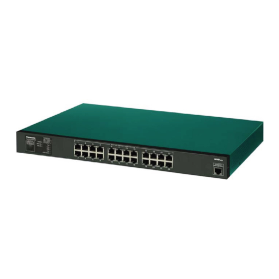
Switch-S24GPWR
Model Number: PN25249
Advertisement
Table of Contents

Related Manuals for Panasonic PN25249


Summary of Contents for Panasonic PN25249
- Page 1 Switch-S24GPWR Operation Manual Model Number: PN25249 for Web Interface Thank you for purchasing our product. This manual provides important information about safe and proper operations of this Switching Hub. Please read "Important Safety Instructions" on pages 3 to 5 before use.
- Page 2 The target model for this Operation Manual is as follows. Model name Model number Firmware version Switch-S24GPWR PN25249-ID 1.0.0.07 and above PN25249-TH PN25249-MY PN25249-SG...
-
Page 3: Important Safety Instructions
Important Safety Instructions Please Follow the Instructions This chapter contains important safety instructions for preventing bodily injury and/or property damage. You are required to follow them. ■Severity of bodily injury and/or property damage, which could result from incor- rect use of the Switching Hub, are explained below. This symbol indicates a potential hazard that could result in serious injury or death. - Page 4 ●Do not please this Switching Hub in harsh environment(such as near water, high humid, and/or high dust). Deviation could lead to fire, electric shock, and/or equipment failure. ●Do not place this Switching Hub under direct sunlight and/or high tem- perature. Deviation could lead to high internal temperature and fire.
- Page 5 ●Connect the power cord firmly to the power port. Deviation could lead to electric fire, shock, and/or malfunction. ●Unplug the power cord if the Status/ECO LED (Status/ECO mode), blinks in orange (system fault). Deviation, such as keeping connected for a long time, could lead to fire.
-
Page 6: Basic Instructions For The Use Of This Product
Basic Instructions for the Use of This Product ●For inspection and/or repair, consult the retailer. ●Use commercial power supply from a wall socket, which is close and easily accessible to this Switching Hub. ●Unplug the power cord when installing or moving this Switching Hub. ●Unplug the power cord when cleaning this Switching Hub. - Page 7 ●When mounting Switching Hubs in a rack, leave a minimum of 20 mm space between them. 1. Panasonic will not be liable for any damage resulting from the operation not in accordance with this operation manual, or loss of communications, which may or may not be caused by failure and/or malfunction of this device.
-
Page 8: Table Of Contents
Table of Contents Important Safety Instructions ................3 Basic Instructions for the Use of This Product ............. 6 Product Outline ..................10 Web Browser-based Control ..............11 2.1. System Requirements ................11 2.2. Access to Web Control Function ............12 2.3. - Page 9 3.2.16.PoE Display Schedule By Port ............55 3.2.17.Loop Detection Config ..............56 3.2.18.Loop History Info ................57 3.3. System Tools ..................58 3.3.1.Software Update ................58 3.3.2.Reboot .................... 59 3.3.3.Save Current Config ................ 60 3.3.4.Statistics ..................61 3.3.5.System log ..................64 3.3.6.Config File Transfer .................
-
Page 10: Product Outline
1. Product Outline Thank you for purchasing Switch-S24GPWR (hereinafter called "this switch"). This manual provides information required to use the Web control function and the e- mail notification function of this switch. -
Page 11: Web Browser-Based Control
2. Web Browser-based Control The Web browser-based control function (hereinafter called the Web control func- tion) allows you to configure and monitor this Switching Hub over the network via the user interface of your Web browser. You can also control this Switching Hub from a remote location as if it is at your fingertips because the LED statuses can be displayed. -
Page 12: Access To Web Control Function
2.2. Access to Web Control Function To use the Web control function, enter the IP address of this Switching Hub in the URL (such as "Location:" and "Address:") field of your Web browser and press the Enter key. Then, a login screen, similar to Figure 2-1, is displayed. Enter your user name and password. - Page 13 If you are successfully authenticated, a main screen, similar to Figure 2-2, is dis- played. Figure 2-2 Main Screen...
- Page 14 The left side of the screen shows a list of actions available to you on this screen. (1) General Info Displays a list of basic information of this Switching Hub. (2) Basic Config Configure the basic settings such as IP address and port settings. (3) Advanced Config Configure the advanced settings such as VLAN, QoS, and IGMP snooping.
-
Page 15: Display Of Switch Information
2.3. Display of Switch Information Selecting "General Information" opens the screen shown in Figure 2-3. This screen shows a list of basic information of this Switching Hub. Figure 2-3 General Information... - Page 16 Screen Description Operationg Displays the cumulative time since the power-on of this Switching Hub. Time Boot Code Displays this Switching Hub's firmware version. Version * The firmware update described in Section 3.3.1 is available only for runtime codes. Runtime Code Version Hardware Displays the hardware information.
-
Page 17: Switch Configuration
3. Switch Configuration After completing configuration, you must save the configuration information in accordance with Section 3.3.3. Unless the configuration information is saved, the settings configured so far will not be reflected after restart. 3.1. Basic Config 3.1.1. Administration Configration Select "Basic Config"... -
Page 18: Ip Config
3.1.2. IP Config Select "Basic Config" and "IP Config" to open the screen shown in Figure 3-2. On this screen, you can configure the IP address of this Switching Hub. Figure 3-2 IP Config Screen Description DHCP Mode Displays whether the DHCP client is enabled or disabled. Enable Enables the DHCP client. -
Page 19: Basic Port Configration
3.1.3. Basic port Configration Select "Basic Config" and "Port Config" and then "Basic Port Configuration" to open the screen shown in Figure 3-3. On this screen, you can configure port status dis- play settings and mode and other settings. Figure 3-3 Basic Port Configration... - Page 20 Screen Description Port Number Displays the port number. Trunk Displays the group number for a trunked port. Type Displays the port type. 100TX The port type is 10/100BASE-TX. 1000T The port type is 1000BASE-T. Port Status Displays the current port status. For all ports, "Enable" is the factory default set- ting.
-
Page 21: Extend Port Configration
3.1.4. Extend Port Configration Select "Basic Config" and "Port Config" and then "Extend Port Config" to open the screen shown in Figure 3-4. On this screen, you can configure port status display settings and mode and other settings. Figure 3-4 Extend Port Configration Screen Description Port Number Displays the port number. -
Page 22: Power Saving Port Configration
3.1.5. Power Saving Port Configration Select "Basic Config" and "Port Config" and then "Power Saving Port Config" to open the screen shown in Figure 3-5. On this screen, you can configure the power saving settings of ports. Figure 3-5 Power Saving Port Configration Screen Description Port Number Displays the port number. -
Page 23: System Security
Access is disabled. IP Setup Displays the access settings for the IP address configuration software, bundled Interface Status with the Panasonic network cameras. "Enable" is the factory default setting.* For instructions, refer to Appendix C. Enable Access is enabled. Disable Access is disabled. -
Page 24: Telnet Access Limit
3.1.7. Telnet Access Limit Select "Basic Config" and "System Security" and then "Telnet アクセス設定 " to open the screen shown in Figure 3-7. On this screen, you can configure the Telnet access limitation. Figure 3-7 Telnet Access Limit Screen Description Global Telnet Displays the Telnet access limitation setting. -
Page 25: Id/Password Change
3.1.8. ID/Password Change Select "Basic Config" and "System Security" and then "ID/Password Change" to open the screen shown in Figure 3-8. On this screen, you can configure the user- name/password. Figure 3-8 ID/Password Change Screen Description Current User ID Enter the current username. This setting is used to log in to this Switching Hub. -
Page 26: Mac Learning
3.1.9. MAC Learning Select "Basic Config" and "System Security" and then "MAC Learning" to open the screen shown in Figure 3-9. On this screen, you can configure the MAC Learning settings of ports. Figure 3-9 Telnet Access Limit Screen Description Port Number Displays the port number. -
Page 27: Fdb Manual Setting
3.1.10. FDB Manual Setting Select "Basic Config" and "FDB" and then "FDB Manual Setting" to open the screen shown in Figure 3-10. On this screen, you can register the MAC address statistically in the FDB table. Figure 3-10 FDB Manual Setting Screen Description Port (Add) Select a port to which a MAC address is to be added. -
Page 28: Fdb Table
3.1.11. FDB Table Select "Basic Config" and "FDB" and then "FDB Table" to open the screen shown in Figure 3-11. This screen shows the MAC addresses learned in the FDB table by port. Figure 3-11 FDB Table (by Port) Screen Description Aging Displays the time for which an FDB table is retained. -
Page 29: Time Configration
3.1.12. Time Configration Select "Basic Config" and "Time Config" to open the screen shown in Figure 3-12. On this screen, you can configure the time settings and the SNTP-based time syn- chronization settings. Figure 3-12 Time Configration of This Switching Hub Screen Description Time Zone Displays the time zone. -
Page 30: Static Arp Table
3.1.13. Static ARP Table Select "Basic Config" and "ARP Table" and then "Static ARP Table" to open the screen shown in Figure 3-13. On this screen, you can register an ARP table while statistically associating the IP address and MAC address to it. Figure 3-13 Static ARP Table Screen Description IP Address... -
Page 31: Arp Table
3.1.14. ARP Table Select "Basic Config" and "ARP Table" and then "ARP Table" to open the screen shown in Figure 3-14. This screen shows the ARP Table. Figure 3-14 ARP Table Screen Description ARP Age Displays the time for which an ARP table is retained. It is equal to the time after Timeout receiving the last packet. -
Page 32: Advanced Switch Configuration
3.2. Advanced Switch Configuration 3.2.1. VLAN Management Select "Advanced Config" and "VLAN" and then "VLAN Management" to open the screen shown in Figure 3-15. On this screen, you can configure the specified VLAN settings. Figure 3-15 VLAN Management Screen Description VLAN Total Displays the Switching Hub's current number of VLANs. -
Page 33: Vlan Modification
3.2.1.a. VLAN Modification On the "VLAN Management" screen, select "Modify" to open the screen shown in Figure 3-16. On this screen, you can modify the VLAN configuration information. Figure 3-16 VLAN Modification Screen Description VLAN ID Displays the VLAN ID. VLAN Name Displays the VLAN name. -
Page 34: Vlan Creation
3.2.2. VLAN Creation Select "Advanced Config" and "VLAN" and then "VLAN Creation" to open the screen shown in Figure 3-17. On this screen, you can create a new VLAN. Figure 3-17 VLAN Creation Screen Description VLAN ID Set the VLAN ID. VLAN Name Set the VLAN name. -
Page 35: Vlan Port Config
3.2.3. VLAN Port Config Select "Advanced Config" and "VLAN" and then "VLAN Port Config" to open the screen shown in Figure 3-18. On this screen, you can configure the specified VLAN port settings. Figure 3-18 VLAN Port Config Screen Description Port Number Displays the port number. -
Page 36: Qos Config
3.2.4. QoS Config Select "Advanced Config" and "QoS Config" and then "Traffic Class Config" to open the screen shown in Figure 3-19. On this screen, you can configure the QoS set- tings. Figure 3-19 QoS Config Screen Description Displays the setting of the QoS function using IEEE802.1p. "Disable"... -
Page 37: Diffserv Config
3.2.5. Diffserv Config Select "Advanced Config" and "QoS Config" and then "Dffserv Config" to open the screen shown in Figure 3-20. On this screen, you can configure the Diffserv set- tings. Figure 3-20 Diffserv Config Screen Description Diffserv Status Displays the Diffserve function setting. "Disable"... -
Page 38: Link Aggregation Config
3.2.6. Link Aggregation Config Select "Advanced Config" and "Link Aggregation Config" to open the screen shown in Figure 3-21. On this screen, you can configure the group settings of link aggre- gation. Figure 3-21 Link Aggregation Config Screen Description Displays the group number of link aggregation. Mode of Operation Displays the operation mode of link aggregation. -
Page 39: Link Aggregation Modification
3.2.6.a. Link Aggregation Modification Select "Advanced Config" and "Link Aggregation Config" and then click the "Mod- ify" button of a group to open the screen shown in Figure 3-22. On this screen, you can modify the link aggregation. Figure 3-22 Link Aggregation Modification Screen Description Mode Displays the operation mode of link aggregation. -
Page 40: Port Monitoring Configration
3.2.7. Port Monitoring Configration Select "Advanced Config" and "Port Monitoring Config" to open the screen shown in Figure 3-23. On this screen, you can configure the port monitoring settings. Figure 3-23 Port Monitoring Configration Screen Description Monitor Output Displays the port number of a port at which packets from other ports can be Port monitored. - Page 41 Note: Administrative packets such as Ping and ARP transmitted by this Switching Hub cannot be captured.
-
Page 42: Poe Port Configration
3.2.8. PoE Port Configration Select "Advanced Config" and "PoE Config" and then "PoE Port Config" to open the screen shown in Figure 3-24. On this screen, you can configure the power supply settings by port. Figure 3-24 PoE Port Configration... - Page 43 Screen Description Port Number Displays the port number. Admin Displays whether or not power can be supplied. Power can be supplied. Down Power cannot be supplied. Status Displays the power supply status. Powered Power is supplied. Not Powered Power is not supplied. Overload More power than the limit is supplied.
-
Page 44: Poe Global Configration
3.2.9. PoE Global Configration Select "Advanced Config" and "PoE Config" and then "PoE Grobal Config" to open the screen shown in Figure 3-25. On this screen, you can configure the general PoE settings. Figure 3-25 PoE Grobal Configration Screen Description Power Budget Displays the maximum amount of power this Switching Hub can supply. -
Page 45: Poe Schedule Port List Info
3.2.10. PoE Schedule Port List Info Select "Advanced Config" and "PoE" and then "PoE Schedule Port List Info" to open the screen shown in Figure 3-26. This screen displays the port list for PoE schedule. Figure 3-26 PoE Schedule Port List Info Screen Description Index Displays the index number of the PoE port list. -
Page 46: Poe Schedule Port List Config
3.2.11. PoE Schedule Port List Config Select "Advanced Config" and "PoE" and then "PoE Schedule Port List Config" or, on the "PoE Schedule Port List Info" screen, select "Modify" to open the screen shown in Figure 3-27. This screen displays the port list for PoE schedule. Figure 3-27 PoE Schedule Port List Config Screen Description Index... -
Page 47: Poe Schedule Info
3.2.12. PoE Schedule Info Select "Advanced Config" and "PoE" and then "PoE Schedule Info" to open the screen shown in Figure 3-28. This screen displays the PoE schedule that has been configured. Figure 3-28 PoE Schedule Info Screen Description PoE Schedule Displays the status of the PoE schedule function. - Page 48 Active Displays the action of the PoE schedule. Turns on PoE. Turns off PoE. OFF/ON Turns off and on PoE (RESTART). Status Displays the status of the PoE schedule function of the port. Enable Enables the PoE schedule function of the port. Disable Disables the PoE schedule function of the port.
-
Page 49: Poe Schedule Config
3.2.13. PoE Schedule Config Select "Advanced Config" and "PoE" and then "PoE Schedule Config" or, on the "PoE Schedule Info" screen, select "Modify" to open the screen shown in Figure 3- 29. On this screen, you can create or modify a PoE schedule. Figure 3-29 PoE Schedule Config... - Page 50 Figure 3-30 PoE Schedule Config (Daily) Figure 3-31 PoE Schedule Config (Weekly)
- Page 51 Figure 3-32 PoE Schedule Config (Monthly) Figure 3-33 PoE Schedule Config (DateList)
- Page 52 Screen Description Index Displays the index number of PoE schedule information. Status Displays the status of the PoE schedule function of the port. Enable Enables the PoE schedule function of the port. Disable Disables the PoE schedule function of the port. Name Displays the name of the PoE schedule.
-
Page 53: Date List Info
3.2.14. Date List Info Select "Advanced Config" and "PoE" and then "Date List Info" to open the screen shown in Figure 3-34. This screen displays the date list that has been configured. Figure 3-34 Date List Info Screen Description Index Displays the index number of the date list. -
Page 54: Date List Config
3.2.15. Date List Config Select "Advanced Config" and "PoE" and then "Date List Config" or, on the "Date List Info" screen, select "Modify" to open the screen shown in Figure 3-35. On this screen, you can create or modify a date list. Figure 3-35 Date List Config Screen Description Index... -
Page 55: Poe Display Schedule By Port
3.2.16. PoE Display Schedule By Port Select "Advanced Config" and "PoE" and then "PoE Display Schedule By Port" to open the screen shown in Figure 3-36. This screen displays the PoE schedule by port that has been configured. Figure 3-36 PoE Display Schedule By Port Screen Description Port Number Specify a port number. -
Page 56: Loop Detection Config
3.2.17. Loop Detection Config Select "Advanced Config" and "Loop Detection" and then "Loop Detection Config" to open the screen shown in Figure 3-37. On this screen, you can configure addi- tional settings. Figure 3-37 Loop Detection Config Screen Description Global Loop Detec- Displays the status of the Global Loop Detection function. -
Page 57: Loop History Info
3.2.18. Loop History Info Select "Advanced Config" and "Loop Detection" and then "Loop History Info" to open the screen shown in Figure 3-38. On this screen, you can configure additional settings. Figure 3-38 Loop History Info Screen Description Number Displays the loop detection event number. Time Displays the time when the loop detection event occurred. -
Page 58: System Tools
3.3. System Tools 3.3.1. Software Update Select "System Tools" and "Software Update" to open the screen shown in Figure 3- 39. On this screen, you can update the firmware. Figure 3-39 Software Update Screen Description Current Firmaware Version Displays the current firmware version. TFTP Server Displays the IP address of the TFTP server on which the firmware for IP Address... -
Page 59: Reboot
3.3.2. Reboot Select "System Tools" and "Reboot" to open the screen shown in Figure 3-40. On this screen, you can reboot this Switching Hub. Figure 3-40 Reboot Screen Description Reboot Option Displays the reboot method. "Normal" is the factory default setting. Normal Normal reboot is conducted. -
Page 60: Save Current Config
3.3.3. Save Current Config Select "System Tools" and "Save Current Config" to open the screen shown in Fig- ure 3-41. On this screen, you can save configuration information. Figure 3-41 Save Current Config Click Save to save this Switching Hub's settings to its internal RAM. Unless the con- figuration information is saved, the settings configured so far will not be reflected after restart. -
Page 61: Statistics
3.3.4. Statistics Select "System Tools" and "Ststistics" to open the screen shown in Figure 3-42. On this screen, you can check the statistic information. Figure 3-42 統計情報 Screen Description Target Port Displays the port number. Number Time Displays the time elapsed since power-on or counter reset. Counter Name Displays the counter name. - Page 62 The counter values are listed below. Total RX Bytes Displays the number of bytes of all packets received. Total RX Pkts Displays the number of all packets received. Good Broadcast Displays the number of broadcast packets received. Good Multicast Displays the number of multicast packets received. CRC/Align Errors Displays the number of error packets that have a normal packet length (64 to 1518 bytes);...
- Page 63 Click a counter name to open the screen shown in Figure 3-43. This screen displays the totals and per-second averages of the counter by port. Figure 3-43 Statistic Information of a Counter by Port Screen Description Port Number Displays the port number. Total Displays the counter value.
-
Page 64: System Log
3.3.5. System log Select "System Tools" and "System log" to open the screen shown in Figure 3-44. This screen displays the logs of events that occurred on this Switching Hub. By viewing events, you can keep track of phenomena that occurred on this Switching Hub, which are useful for network management. - Page 65 Screen Description Entry Displays the event number. Time Displays the time when the event occurred. The cumulative time since power-on is displayed if 時刻設定 is not configured. Event Displays the description of the event that occurred on this Switching Hub. Login from console There was login from the console port .
-
Page 66: Config File Transfer
3.3.6. Config File Transfer Select "System Tools" and "Config File Transfer" to open the screen shown in Figure 3-45. On this screen, you can upload and download configuration files. Figure 3-45 Config File Transfer Screen Description TFTP Server IP Displays the IP address of the TFTP server that saves and reads configuration infor- mation. -
Page 67: Ping Execution
3.3.7. Ping Execution Select "System Tools" and "Ping Execution" to open the screen shown in Figure 3- 46. On this screen, you can send a ping. Figure 3-46 Ping Execution Screen Description Target IP Address Displays the IP address of the target to which a ping is sent. "0.0.0.0" is the factory default setting. -
Page 68: Exception Handler
3.3.8. Exception Handler Select "System Tools" and "Exception Handler" to open the screen shown in Figure 3-47. On this screen, you can configure the Exception Handler settings. Figure 3-47 Exception Handler Screen Description Exception Handler Displays the status of the Exception Handler function. Enable Enables the Exception Handler. -
Page 69: Watchdog Timer
3.3.9. Watchdog Timer Select "System Tools" and "Watchdog Timer" to open the screen shown in Figure 3- 48. On this screen, you can set the Watchdog Timer settings. Figure 3-48 Watchdog Timer Screen Description Watch Dog Timer Displays the status of the Watchdog Timer function. Enable Enables the Watchdog Timer. -
Page 70: Appendix
Appendix 4.1. Specifications ○ Interfacez - Twisted-pair ports: Ports 1 to 24 (RJ45 connector) Transmission system IEEE802.3 10BASE-T IEEE802.3u 100BASE-TX IEEE802.3ab 1000BASE-T - Console port x 1 (RJ45 connector) RS-232C (ITU-TS V.24) ○ Switching system - Store-and-forward system - Forwarding rate 10BASE-T 14,880 pps... - Page 71 - Storage temperature -20 to 70 ℃ - Storage humidity 10 to 90 % RH (no condensation) ○ External specifications - Dimensions 44mm (Height) x 440mm( (Width) x 256 mm (Depth) (Excluding protruding sections) - Mass (Weight) 3,600 g...
-
Page 72: Easy Ip Address Setup Function
The following are points to note when using the easy IP address setup function. [Known compatible software] Panasonic Eco Solutions Networks Co., Ltd. "ZEQUOassistPlus" Ver. 1.1.1.0 Panasonic Corporation "Easy IP Setup" V3.01/V4.00/V4.24R00 Panasonic System Networks Co., Ltd. "Easy Config" Ver3.10R00... -
Page 73: Troubleshooting
5. Troubleshooting If you find any problem, please take the following steps to check. ◆ LED indicators ■ The power LED (POWER) is not lit. ● Is the power cord connected? Please confirm that the power cord is securely connected to the power port. ●... - Page 74 ◆ PoE power supply is impossible. ■ The PoE power supply LED (PoE) is not lit. ● Is the LED mode set to the Power supply mode (PoE)? → Select the Power supply mode LED (PoE) by pressing the LED switch but- ton.
-
Page 75: After-Sales Service
6. After-sales Service 1. Warranty card A warranty card is included in the operating instructions (paper) provided with this Switching Hub. Be sure to confirm that the date of purchase, shop (com- pany) name, etc., have been entered in the warranty card and then receive it from the shop. - Page 76 (* You can check the version on the screen described in Section 4.2 of the Operation Man- ual - for Menu Interface.) © Panasonic Eco Solutions Networks Co., Ltd. 2014-2016 Panasonic Eco Solutions Networks Co., Ltd. 2-12-7, Higashi-Shimbashi, Minato-ku, Tokyo Japan, 105-0021 URL: http://panasonic.co.jp/es/pesnw/english/...