
Related Manuals for Ludlum Measurements 2200


Summary of Contents for Ludlum Measurements 2200
- Page 1 LUDLUM MODEL 2200 SCALER RATEMETER March 2016 Serial No. 185785 and Succeeding Serial Numbers...
- Page 2 LUDLUM MODEL 2200 SCALER RATEMETER March 2016 Serial No. 185785 and Succeeding Serial Numbers...
-
Page 3: Statement Of Warranty
RETURN OF GOODS TO MANUFACTURER If equipment needs to be returned to Ludlum Measurements, Inc. for repair or calibration, please send to the address below. All shipments should include documentation containing return shipping address, customer name, telephone number, description of service requested, and all other necessary information. -
Page 7: Table Of Contents
Table of Contents 1. INTRODUCTION ............................ 1 2. SPECIFICATIONS ........................... 2 3. DESCRIPTION OF CONTROLS AND FUNCTIONS ................4 ............................4 RONT ANEL ............................. 5 ANEL ..........................5 NTERNAL ONTROLS 4. SAFETY CONSIDERATIONS AND WARNING MARKINGS ............6 ................. 6 NVIRONTMENTAL ONDITIONS FOR ORMAL... - Page 8 418) ....................23 IRING IAGRAM RAWING APPENDIX A – CALIBRATION PROCEDURE ................... A-1 APPENDIX B – ELECTRONICS CHECKOUT PROCEDURE ............. B-1 APPENDIX C – SCALER PRINTER OPTION ..................C-1 ........................C-1 RINTER PECIFICATIONS ........................... C-1 ONFIGURATION APPENDIX D – DRAWINGS AND DIAGRAMS.................. D-1 ...
-
Page 9: Introduction
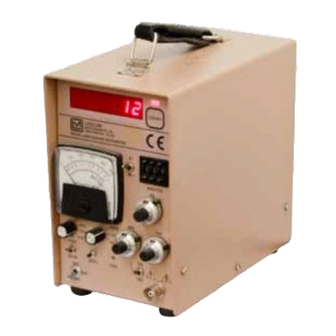
Model 2200 Scaler Ratemeter Section Introduction The Model 2200 Scaler Ratemeter is a self-contained counting instrument designed for operation with scintillation, proportional, or GM (Geiger Muller) detectors. Counting information is displayed both as a scaler count on the LED (light-emitting diode) display and as an averaged count rate on the analog scaler. -
Page 10: Specifications
Model 2200 Scaler Ratemeter Section Specifications 1 mA, 6.4 cm (2.5 in.) scale, self-shielded DC mechanism Meter: four-decade, linear ratemeter with ranges of 0-500; 0-5000; 0- Ratemeter: 50,000; and 0-500,000 cpm (counts per minute); 6.4 cm (2.5 in.) scale panel meter;... - Page 11 Model 2200 Scaler Ratemeter -20 to 50 °C (-4 to 122 °F); may be certified to operate Temperature Range: from -40 to 65 °C (-40 to 150 °F) 21.6 x 12.7 x 21.6 cm (8.5 x 5 x 8.5 in.) (H x W x L), excluding handle...
-
Page 12: Description Of Controls And Functions
Model 2200 Scaler Ratemeter Section Description of Controls and Functions Front Panel COUNT LAMP: a red LED, indicating that the scaler is in the count cycle. COUNT SWITCH: resets and starts the scaler counting. The scaler turns off at the end of the preset time. -
Page 13: Rear Panel
Model 2200 Scaler Ratemeter ZERO Switch: When depressed, this switch discharges the integrating capacitor, driving the meter to zero. F-S Response: a two-position toggle switch indicating fast or slow response. In “F” position, the meter will deflect from 10 to 90% of full scale in 4 seconds. In “S” potion, the meter will deflect from 10 to 90% of full scale in 22 seconds. -
Page 14: Safety Considerations And Warning Markings
Pollution Degree 2 (as defined by IEC 644) Cleaning Instructions and Precautions The Model 2200 may be cleaned externally with a damp cloth, using only water as the wetting agent. Do not immerse the instrument in any liquid. Observe the following precautions when cleaning: 1. -
Page 15: Warning Markings And Symbols
The operator or responsible body is cautioned that the protection provided by the equipment may be impaired if the equipment is used in a manner not specified by Ludlum Measurements, Inc. Caution! Verify instrument voltage input rating before connecting to a power converter. -
Page 16: Replacement Of Fuses
Model 2200 Scaler Ratemeter The “crossed-out wheelie bin” symbol notifies the consumer that the product is not to be mixed with unsorted municipal waste when discarding; each material must be separated. See section 8, “Recycling” for further information. Also displayed on the side panel. -
Page 17: Operationg Procedures
Model 2200 Scaler Ratemeter Section Operating Procedures Power Select either line or battery operation with the power switch. Line Operation: Connect the instrument to line power of 95-250 Vac, 50-60 Hz. Turn the power switch to LINE and proceed to use the instrument. -
Page 18: Operating Point
Model 2200 Scaler Ratemeter Adjust DISCR until scaler meter reaches 75% of generated, incoming count rate. The input sensitivity is now set for 10 mV with THRESHOLD set for 1.00. Proceed to use instrument with THRESHOLD setting at 1.00 or more. -
Page 19: Determining Instrumetn Plateau
Model 2200 Scaler Ratemeter graph, relating count rate to system gain. This relationship is commonly referred to as a plateau or instrument plateau curve. System gain may be changed by adjusting detector high voltage (HV), THRESHOLD control or DISCR (amplifier gain). -
Page 20: Window Operation And Energy Calibration Procedures
Window Operation and Energy Calibration Procedures General The Model 2200 is calibrated at the factory so that one turn on the THRESHOLD controls is equal to one turn on the window dial. Equipment Required Detectors capable of energy discrimination. Examples used are the Ludlum Models 44-3 and 44-2. -
Page 21: Procedure To Calibrate Threshold To 100 Ke V/Turn
55 keV and 65 keV. Adjust the THRESHOLD dial for other energies of interest. Procedures to Calibrate Threshold to 100 keV/Turn Initial Model 2200 control settings: Switch the window ON-OFF to OFF. Ratemeter RANGE selector switch at X10. THRESHOLD dial is at 6.42. -
Page 22: Data Output
Section Data Output General The Model 2200 RS-232 serial port can be connected to a computer or printer for data-logging of the scaler count information. Windows -based software and cable are supplied with the instrument. The computer software can control the count time, start and stop counting, time/data stamp data, and print or save data. -
Page 23: Button Functions
Model 2200 Scaler Ratemeter 3. Prior to running the program, ensure that the Model 2200 is in the PC mode, and the count time push-wheels are set to 000. Button Functions Start/Stop Count: Click on this button to start a count. Clicking on it again will hold the count. -
Page 24: Rs-232 Commands
Model 2200 Scaler Ratemeter RS-232 Commands The Model 2200 communicates by way of the RS-232 interface. The RS-232 port operates at 2400 baud, 8 data bits, 1 stop bit, no parity, and hardware (RTS/CTS) flow control. A standard RS-232 cable with straight-through connections is required. -
Page 25: Recycling
To this end, Ludlum Measurements, Inc. strives to supply the consumer of its goods with information regarding reuse and recycling of the many different types of materials used in its products. -
Page 26: Parts List
Model 2200 Scaler Ratemeter Section Parts List Reference Description Part Number Model 2200 Scaler UNIT Completely Assembled Ratemeter Model 2200 Scaler Ratemeter 48-1651 BOARD Assembled Board 5167-413 Main Board, Drawing 167 x 413 MICRO 6.144 MHZ 01-5262 CRYSTAL C1-C3 100pf, 100V... - Page 27 Model 2200 Scaler Ratemeter C48-C60 0.001µF, 2kV 04-5703 68µF, 10V 04-5654 10µF, 25V 04-5728 C64-C65 0.1µF, 50V 04-5663 Reference Description Part Number REG-LT1406KCS3 05-5867 TRANSISTORS MAX810LEUR 06-6424 INTEGRATED U1-U2 LM358D 06-6312 CIRCUITS CA3096M 06-6288 LT1304CS8-5 06-6434 CD74HC4538M 06-6297 LM828M5 06-6518...
-
Page 28: Amplifier Board (Drawing 167 X 392)
Model 2200 Scaler Ratemeter 10k, 1/8W, 1% 12-7839 Reference Description Part Number 100k TRIMMER 09-6823 R33-R35 1MEG TRIMMER 09-6828 4.75k, 1/8W, 1% 12-7858 10OHM, 1W, 1% 12-7952 R39-R40 33.2k, 1/8W, 1% 12-7842 R45-R46 22.1k, 1/8W, 1% 12-7843 82.5k, 1/8W, 1%... - Page 29 Model 2200 Scaler Ratemeter Reference Description Part Number 0.1µF, 50V 04-5663 C19-C20 10µF, 25V 04-5728 100pf, 100V 04-5661 C22-C23 0.1µF, 50V 04-5663 MMBT3904LT1 05-5841 TRANSISTORS 2N7002L 05-5840 RESISTORS 100OHM, 1/8W, 1% 12-7840 R3-R5 1k, 1/8W, 1% 12-7832 R6-R8 100k, 1/8W, 1% 12-7834 5.62k, 1/8W, 1%...
-
Page 30: Switch Board
Model 2200 Scaler Ratemeter Reference Description Part Number BOARD Assembled Board 5167-336 Switch Board, Drawing 167 x 273 100µF, 10V, C 04-5576 CAPACITORS 10k TRIMMER 09-6787 RESISTORS TT11DGPC9T 08-6769 TP11LTCQE 08-6770 SWITCHES SW3-SW4 56DP36-01-2-AJN 08-6766 1-640456-1 MTA100 13-8059 CONNECTORS 640456-2 MTA100... -
Page 31: Wiring Diagram, Drawing 167 X 418
Model 2200 Scaler Ratemeter Reference Description Part Number Wiring Diagram, Drawing 167 x 418 MTF206P 08-6780 SWITCHES SW2-SW3 7101-SYZ-QE 08-6511 R1-R3 10k, 10-TURN POT 09-6761 RESISTORS 747020-2 RS232 13-8555 CONNECTORS UG706/U “C” LMI 4478-011 640428-3 MTA156 13-8124 640442-5 MTA100 13-8140... -
Page 32: Appendix A - Calibration Procedure
Model 2200 Scaler Ratemeter Appendix A – Calibration Procedure Ludlum Measurements, Inc. Page A-1 March 2016... -
Page 37: Appendix B - Electronics Checkout Procedure
Model 2200 Scaler Ratemeter Appendix B – Electronics Checkout Procedure Ludlum Measurements, Inc. Page B-1 March 2016... -
Page 42: Appendix C - Scaler Printer Option
Model 2200 Scaler Ratemeter Appendix C – Scaler Printer Option Ludlum Measurements, Inc. sells a small 40-column serial-input impact printer for use with our new (year 2001) scaler or scaler/ratemeters. This small printer can print the results of each scaler count. -
Page 43: Appendix D - Drawings And Diagrams
Model 2200 Scaler Ratemeter Appendix D – Drawings and Diagrams Main Board, Drawing 167 x 413 (4 sheets) Main Board Component Layout, Drawing 167 x 414 Amplifier Board, Drawing 167 x 392 Amplifier Board Component Layout, Drawing 167 x 393A...
Need help?
Do you have a question about the 2200 and is the answer not in the manual?
Questions and answers