Table of Contents

Related Manuals for THUNDER TIGER RAPTOR


Summary of Contents for THUNDER TIGER RAPTOR
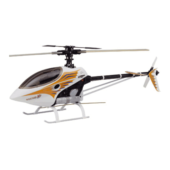
- Page 2 3-dimensional space. Its docile handling is ideally suited for beginners. The stable hover and agility also make it the top choice for contest fliers and extreme 3-D pilots. The Raptor requires the least amount of assembly of any helicopter kit. The ARF version comes complete with a high performance Thunder Tiger Pro 70H ring engine and muffler.
-
Page 3: Other Items Required
Tools for Assembly The Raptor 60 design has a low parts count. It is designed for easy maintenance using standard hobby tools. Please only use genuine Thunder Tiger parts. Please keep the model clean and well tuned. It will provide you with long lasting pleasure in return. - Page 4 Thunder Tiger products are distributed by Ace Hobby Distributors. On the web site www.acehobby.com, there is a list of all the hobby shops in the USA that can special order any Thunder Tiger parts from Ace for you. Technical questions on the Raptor will be answered quickly sending an email to service@acehobby.com or call Technical Support at 949-...
- Page 5 Please monitor the fuel level during flight so you do not run out of fuel during flight. Before each flight, please check that all servos and controls move properly. Do not modify any parts or use other than genuine Thunder Tiger parts. Do not fly in places that are forbidden by law.
-
Page 6: Main Frame Assembly
MAIN FRAME ASSEMBLY For the kit, parts are bagged according to each major assembly and are labeled "Bag A, Bag B, etc." You will note that the heading for each assembly indicates which bag correlates with each assembly. As a good practice, only open up the bag that you need for the particular assembly. - Page 7 BAG A Upper Frame Assembly No. Material No. Description No. Material No. Description HMC3-8B M3x8 Socket Screw BK0393 Pitch Frame Cross Member HMC3-10B M3x10 Socket Screw BK0394 Pitch Frame Cross Member Nut HSA3-22 M3x22 Button Head Socket Screw 1-1-2 Pinion Gear Subassembly BK0087 d3xD8x1.4 Washer 1-1-1...
-
Page 8: Pinion Gear Subassembly
1-1-2 Pinion Gear Subassembly No. Material No. Description HMV6800Z d10xD19x5 BRG HME4-5B M4x5 Set Screw HMS5 M5x8 E Ring HMV1360Z d6xD13x5 BRG (11) HMV696Z d6xD15x5 BRG BK0388 Clutch BRG Case BK0391 Frame Spacer M BK0594 Starter Coupling BK0592 Starter Shaft 10 BK0355 Drive Pinion 11 BK0366... - Page 9 BAG B Lower Frame Assembly No. Material No. Description No. Material No. Description BK0390 Frame Spacer L BK0376 Lower Metal Frame HMC3-8B M3x8 Socket Screw BK0380 Rear Frame L HMC3-10B M3x10 Socket Screw BK0381 Rear Frame R HMC3-12B M3x12 Socket Screw 1-2-2 Tail Drive Unit Subassembly BK0087...
-
Page 10: Tail Drive Unit Subassembly
1-2-2 Tail Drive Unit Subassembly No. Material No. Description HMV6701ZZ d12xD18x4 BRG HME3-4B M3x4 Set Screw Add a small drop of Loctite. HMV1350ZZ d5xD13x4 BRG Make sure it locks the pin. BK0362 Tail Drive Bevel Gear A BK0363 Tail Drive Bevel Gear B BK0364 Tail Drive Pinion BK0365... -
Page 11: Rod Guide Collar Subassembly
BAG C Main Frame Assembly No. Material No. Description HMC3-25B M3x25 Socket Screw BK0087 d3xD8x1.4 Washer BK0103 Body Fitting Pin BK0392 Frame Spacer S 1-3-1 Rod Guide Collar Subassembly Upper Frame Assembly Lower Frame Assembly Insert two hex Frame Spacers S into the plastic Rod Guide Collars (1-3-1). - Page 12 BAG D Installation of Servo Frame No. Material No. Description BK0377 Servo Frame HSE3-12B M3x12 Self-Tapping Screw Main Frame Assembly Install the one-piece servo frame using six self-tapping screws. Do not use Loctite when attaching self-tapping screws to plastic parts. Loctite is only for threading metal into metal parts.
- Page 13 BAG E Installation of Pitch Frame No. Material No. Description No. Material No. Description BK0093 2x46 Link Rod 1-5-2 Elevator Parallel Lever Subassembly HMC3-10B M3x10 Socket Screw 1-5-3 Elevator Control Lever Subassembly HMJ3-20N M3x20 Self-Tapping Screw 1-5-4 Pitch Control Frame Subassembly HMC3-25B M3x25 Socket Screw 1-5-5 Elevator Control Arm Subassembly...
-
Page 14: Aileron Lever Subassembly
1-5-1 Aileron Lever Subassembly No. Material No. Description No. Material No. Description HMJ2-10N M2x10 Self-Tapping Screw HMJ2-10N M2x10 Self-Tapping Screw HMV840ZZ d4xD8x3 BRG HMV840ZZ d4xD8x3 BRG BK0340 Aileron Control Arm BK0340 Aileron Control Arm BK0075 Link Ball 4.8 BK0075 Link Ball 4.8 Add a tiny drop of thick CA glue at the tip of the M2x10 self-tapping screw (No. -
Page 15: Pitch Control Frame Subassembly
1-5-4 Pitch Control Frame Subassembly No. Material No. Description HMJ2-10N M2x10 Self-Tapping Screw HMV840ZZ d4xD8x3 BRG HMV1280 d8xD12x3.5 BRG BK0336 Pitch Frame BK0075 Link Ball 4.8 Optional: add a tiny drop of thick CA on the outside rim of the ball bearings before inserting them into the plastic Pitch Frame. - Page 16 BAG F Installation of Main Shaft No. Material No. Description No. Material No. Description BK0093 2x46 Link Rod BK0234 Lock Ring HMC3-6B M3x6 Socket Screw 1-6-1 Wash Out Subassembly HMM4B M4 Locknut 1-6-2 Swash Plate Subassembly BK0617 M4 Bolt 1-6-3 Main Gear Subassembly BK0360 Main Shaft...
-
Page 17: Wash Out Subassembly
1-6-1 Wash Out Subassembly No. Material No. Description HMJ2-10N M2x10 Self-Tapping Screw HMC3-12B M3x12 Socket Screw HMV840ZZ d4xD8x3 BRG BK0341 Wash Out Base BK0342 Flybar Control Lever BK0343 Wash Out Link BK0075 Link Ball 4.8 BK0409 Collar d3xD4x7 BK0412 Pin 2x14.5 Insert the pin into the Washout Link. -
Page 18: Rotor Head Assembly
ROTOR HEAD ASSEMBLY... - Page 19 BAG G Rotor Head Assembly No. Material No. Description Qty. No. Material No. Description Qty. BK0292 2.3x24 Link Rod BK0086 Ball Link 4.8x20 HMC3-10B M3x10 Socket Screw 2-1-1 Flybar Seesaw Subassembly HMV694ZZ d4xD11x4 BRG 2-1-2 Main Rotor Hub Subassembly BK0408 Collar d3xD4x5.5 Make two pushrods for controlling blade pitch.
-
Page 20: Flybar Seesaw Subassembly
2-1-1 Flybar Seesaw Subassembly BAG G No. Material No. Description Qty. No. Material No. Description Qty. HMJ2-10N M2x10 Selfing-Tapping Screw BK0322 Flybar Seesaw Hub HMC3-18B M3x18 Socket Screw BK0323 Flybar Arm Bushing BK0088 d3xD5x0.5 Washer BK0324 Mixing Lever HMV694ZZ d4xD11x4 BRG BK0434 Flybar Rod (In BAG O) HME4-3B... - Page 21 Important Note: The stock Raptor 60 kits come with black color flap damper that are of 70 degree durometer stiffness. This is good for beginner to advance F3C flying. For aggressive 3D flying, the pilot may choose to an optional red 80 degree durometer hard damper for...
-
Page 22: Tail Assembly
TAIL ASSEMBLY... - Page 23 BAG H Tail Assembly No. Material No. Description No. Material No. Description HMM3B M3 Locknut BK0401 Stabilizer Fin Bracket HSE3-12B M3x12 Self-Tapping Screw BK0404 Tail Rotor Blade HMC3-14B M3x14 Socket Screw BV0423 Tail Drive Shaft BRG (In BAG O) HMC3-30B M3x30 Socket Screw BV0367 Tail Drive Shaft (In BAG O) BK0348...
-
Page 24: Tail Transmission Subassembly
3-1-1 Tail Transmission Subassembly No. Material No. Description Qty. No. Material No. Description Qty. HMV6701Z d12xD18xBRG 10 HMV1350 d5xD13x4 BRG HMJ2-8N M2x8 Self-Tapping Screw 11 BK0346 Tail Pitch Control Lever HMM3B M3 Locknut 12 BK0370 Tail Case L HME3-4B M3x4 Set Screw 13 BK0371 Tail Case R HMC3-10B... -
Page 25: Tail Rotor Subassembly
3-1-2 Tail Rotor Subassembly No. Material No. Description Qty. No. Material No. Description Qty. HMJ2-8N M2x8 Self-Tapping Screw 11 BK0307 Tail Rotor Hub HSE2-10B M2x10 Self-Tapping Screw 12 BK0025 Tail Pitch Control Fork HMC2510B M2.5x10 Socket Screw 13 BK0026 Tail Pitch Control Link HMM25 M2.5 Locknut 14 BK0027... -
Page 26: Final Assembly
FINAL ASSEMBLY... - Page 27 BAG I Installation of Rotor Head Congratulation, we are almost done. Install the finished main No. Material No. Description rotor head onto the 12 mm rotor main shaft. Secure it with a BK0318 2.3x95 Link Rod No. 3 M4x25 socket bolt and No. 2 4 mm locknut. Make up two HMM4B M4 Locknut BK0617...
-
Page 28: Skid Subassembly
Installation of Landing Skid No. Material No. Description HMJ4-22N M4x22 Self-Tapping Screw 4-2-1 Skid Subassembly Make up the landing gear according to the drawing. Do not over tighten the four M4x5 set screws or the plastic brace may crack. After inserting the four plastic end caps into the skids, add some CA glue around the edges to prevent them from falling out. -
Page 29: Tail Support Subassembly
Installation of Tail Assembly No. Material No. Description No. Material No. Description HMM3B M3 Locknut BK0087 d3xD8x1.4 Washer HSE3-12B M3x12 Self-Tapping Screw Tail Assembly HMC3-20B M3x20 Socket Screw 4-3-1 Tail Support Subassembly HMC3-25B M3x25 Socket Screw (1) (5) Slide the finished tail boom into the helicopter. The bolts on the helicopter must be loose in order to insert the tail boom. -
Page 30: Installation Of Peripheral Equipment
INSTALLATION OF PERIPHERAL EQUIPMENT... -
Page 31: Engine Subassembly
BAG J Installation of Engine No. Material No. Description No. Material No. Description 5-1-1 Engine Subassembly HMC4-42B M4x42 Muffler Bolt HMC4-18B M4x18 Socket Screw HMT4B SPRING WASHER BN1639 Muffler Insert the engine into the sideframes, then add the muffler. Add a drop of Loctite on the threads of the M4x42 muffler bolts. - Page 32 BAG J Installation of Servo-Part 1 No. Material No. Description No. Material No. Description HML2 M2 Nut ***** Servo HMF2-8N M2x8 Philip Machine Screw BK0105 Rod Joint BK0436 2.3x55 Link Rod BK0347 Tail Control Rod A (In BAG O) BK0438 2.3x88 Link Rod BK0075 Link Ball 4.8...
- Page 33 BAG J Installation of Servo-Part 2 No. Material No. Description No. Material No. Description HML2 M2 Nut ***** Servo HMF2-8N M2x8 Philip Machine Screw BK0075 Link Ball 4.8 BK0436 2.3x55 Link Rod BK0086 Ball Link 4.8x20 BK0095 2.3x76 Link Rod BK0104 Servo Mounting Plate HSE2614N 2.6x14 Self-Tapping Screw...
- Page 34 BAG K Installation of Receiver & Gyro No. Material No. Description No. Material No. Description ***** Switch JR Type ***** Gyro AMP ***** Swtich Plate ***** Gyro ***** Battery(Recommend 1200mA) BK0106 Two Touch Tape ***** Reciever BE1052 Antenna Pipe Install the receiver and receiver battery. Even though the receiver and battery can be attached to the helicopter tray using double sided foam tape, but it is better to wrap the receiver and battery separately using half inch or 1o mm thick foam.
-
Page 35: Body Subassembly
BAG L Installation of Body No. Material No. Description 5-5-1 Body Subassembly Carefully cut out the transparent canopy (windshield) using a scissors. The best scissors to use are the ones designed to cut RC car bodies. Install the canopy to the body using six small screws. - Page 36 Main Rotor Tiger has now added a complimentary Blade Grip Spacer with BK0446 M5x35 Rotor Bolt each Raptor 60 Kit. This spacer is specially designed for carbon HMM5Z M5 Locknut fiber or fiberglass blades with a 12mm thick blade root. The See wood blade modification in page 41.
- Page 37 SETTINGS...
- Page 38 Setting up Gear Backlash Adjust the Lower BRG Sub-Assembly up- Pinion Gear Sub-Assembly and-down, Pinion Gear Subassembly side- to-side and Engine Mount side-to-side until the gears mesh smoothly and turn freely with a minimum of backlash. Lower BRG Subassembly Engine Mount Setting up of Stabilizer Blade A // B // C Always make sure the surface of the flybar,...
- Page 39 Setting up of Blade Pitch Angle -9˚ -8˚ On the left side frame, there are three pitch scales molded onto the Pitch Guide. The 0˚ three different scales are designed for 12˚ beginner, F3C and 3D pilots. 13˚ Use the "Pointer" on the collective tray and the plastic molded scales to set up the initial collective control.
- Page 40 6-3-2 Collective Travel for F3C For F3C performance, there will be a different setting. The steel linkage ball is at about 13-14mm away from the center of collective servo horn. Adjust the servo rotation at 60˚ so the collective travel range will be between -8˚ and 13˚. The servo horn will be about 14˚...
- Page 41 6-3-4 CONFIGURING THE RAPTOR 60 FOR 3D Use these number as a start only. Pushrod length given Program the radio values into the transmitter. The is from center to center of the ball EXPO should be to reduce the control sensitivity...
-
Page 42: Blade Modification
6. Attach blade grips and tighten screws. 7. Wipe off the excess Epoxy. Dear Raptor Customers: The stock wood blades should be operated with a main rotorspeed of no more than 1700 RPM. For 3D aerobatics or rotor speed more than 1700RPM, it is recommended to use carbon main rotor blades. The above drawing illustrate how to rem ove the plastic blade grips and then carefully slice away some of the covering material, and add the "thin"... - Page 43 Attention Always operate or fly a model helicopter in a safe manner and away from crowd, or spectators, or distractions. Do not operate model helicopters in rainy or windy condition. Check to make sure there is no radio interference before operating a model helicopter. Make sure the transmitter and receiver batteries are fully charged before operation.
- Page 44 Preflight Checklist and Starting Procedure Control system check. (1) The flybar and control paddles must tilt in the proper direction and smoothly through the whole range. (2) The rotor shaft and flybar must be straight and not damaged. (3) The swashplate must remain clean and tilts freely. (4) When control input are given to tilt the swashplate, make sure none of the control arms and pushrods show any binding.
- Page 45 Flying Adjustments (1) Tracking adjustment ... When the two main rotor blades are in track it means their blade tips should follow the same path as they rotate. (1) Rev up the motor until the helicopter becomes light on its skids. increase (2) When the two main rotor blades are in throttle gently...
- Page 46 Flying Adjustments (2) Trimming: All helicopters are inherently unstable. But when a helicopter is properly trimmed, it will not drift away or yaw by itself quickly. Use the following procedure to trim your helicopter. (1) If the helicopter nose starts to yaw left or right, then use the transmitter trim to compensate: yaw right yaw left...
- Page 47 Hover Training (1) Hovering is when the helicopter is floating in a stationary position in the air. Hovering is the fundamental manuever to learn first. Here is the procedure to practice hovering: (1) Make sure there is no spectator anywhere near the model helicopter.
- Page 48 (4) It will take a few hours of hover practice with the helicopter skids at 10 to 20 cm (4-8 inches) off the ground in order to comfortably control the model. Do not try to lift the model to more than 10 to 20 cm(4-8 inches) in the beginning because then the model may tip over readily when the beginner panics and an incorrect command is given.
- Page 49 Forward Flight Training After mastering hovering flight: (1) Start practicing moving the helicopter laterally to the left or right slowly from a 1.5 meter (60 inches) high hover. This is the beginning exercise of translational flight. hovering at 1-1.5 meter (2) After a few hours of practicing step (1) and you are comfortable with translational movement, start using some tail rotor control so the helicopter nose will point slightly to the left or right as you fly it to the left or right.
- Page 50 After Flight Checklist The model helicopter should be thoroughly inspected after each flying session. (1) Check every screw and bolt to make sure none has loosened due to vibration. (2) Check every rotating and movable part to ensure they still move smoothly and normally. (3) Clean off the exhaust residue from the muffler, engine, and helicopter.
- Page 51 In the event the model has crashed. Inspect the flybar, rotor shaft and the blade spindle to make sure they are not bent at all. If any item is damaged, it must be replaced by a new part to ensure safe operation. Do not glue any broken or damaged plastic part. Do not repair broken rotor blades.
-
Page 52: Parts List Section
PARTS LIST SECTION... - Page 53 RAPTOR 60 EXCLUSIVE PARTS RAPTOR 60 EXCLUSIVE PARTS PV0120 MAIN ROTOR GRIP PV0120 MAIN ROTOR GRIP PV0121 FLYBAR CONTROL ARM PV0121 FLYBAR CONTROL ARM PV0122 MAIN ROTOR HUB PV0122 MAIN ROTOR HUB PV0123 MIXING LEVER PV0123 MIXING LEVER PV0124 FLYBAR CONTROL ROD...
- Page 54 PV0146 FLYBAR ROD PV0147 TAIL CASE PV0148 TAIL ROTOR GRIP PV0149 TAIL BEVEL GEAR PV0150 TAIL ROTOR SHAFT PV0151 TAIL ROTOR HUB PV0152 UPPER METAL FRAME SET PV0153 LOWER METAL FRAME SET PV0154 MAIN SHAFT LOWER BRG PV0155 PITCH GUIDE COLLAR SET PV0156 FAN CASING SET PV0157 REAR FRAME SET CASE...
- Page 55 PV0171 BODY PV0172 THRUST BRG PV0174 FLY BAR SEESAW BRG PV0175 FEATHERING BRG PV0176 TAIL PITCH CONTROL LEVER PV0177 ROTOR BOLT PV0178 DECAL PV0179 FRAME SPACER(L) PV0180 FRAME SPACER(M) PV0181 FRAME SPACER(S) PV0182 CLUTCH BELL BRG PV0183 BODY RETAINING SET PV0184 FLYBAR SEESAW PV0185 MAIN SHAFT PV0186 MAIN SPUR GEAR 93T(STD)
- Page 56 PV0198 COOLING FAN ASSY PV0199 TAIL BOOM PV0639 TAIL ROTOR ANGULAR BRG PV0203 STARTER SHAFT BRG PV0534 CLUTCH LINER PV0205 MUFFLER PV0206 CANOPY PV0208 FUEL TANK RUBBER GROMMET PV0209 d4xD11x1.7 WASHER PV0210 d3xD8x1.4 WASHER PV0240 SERVO LINK ROD PV0241 ROD GUIDE COLLAR PV0242 MAIN SHAFT UPPER BRG PV0243 CLUTCH BRG CASE PV0244 PINION BRG...
- Page 57 PV0268 LOCTITE #262 PV0269 GREASE (FOR PLASTIC PV0270 GREASE (FOR BEARING) PV0478 ONEWAY CLUTCH GEAR) GREASE Raptor 30/60 Common Parts PV0041 BALL LINK PV0046 ELEVATOR ARM BRG PV0048 PITCH FRAME ROTOR HUB PV0050 BRG: FEATHERING BRG 4830 SEESAW BRG 4830 TAIL SHAFT BRG 4870 LEVER &...
- Page 58 NAME Parts No. Parts Name quantity Reference Assembly Step PV0041 BALL LINK BK0086 Ball Link 4.8X20 PV0046 ELEVATOR ARM, BRG HMV1280 d8XD12X3.5 BRG 1-5-4 PV0048 BRG: PITCH FRAME & ROTOR HUB HMV840ZZ d4XD8X3 BRG SEESAW 4830/ LEVER & PITCH ARM 4870 PV0050 BRG: FEATHERING 4830/TAIL SHAFT HMV1350...
- Page 59 NAME Parts No. Parts Name quantity Reference Assembly Step HMJ2-14N M2x14 Self-Tapping Screw 1-5-3 PV0134 AILERON LEVER BK0075 Link Ball 4.8 1-5-1 BK0340 Aileron Control Arm 1-5-1 BK0410 Collar d3xD4x13 HMJ2-10N M2x10 Self-Tapping Screw 1-5-1 HMJ3-20N M3x20 Self-Tapping Screw PV0135 TAIL PITCH CONTROL LEVER BK0075 Link Ball 4.8...
- Page 60 NAME Parts No. Parts Name quantity Reference Assembly Step HME3-18B M3x18 Set Screw 3-1-1 HMM3B M3 Locknut 3-1-1 PV0152 UPPER METAL FRAME SET BK0375 Upper Metal Frame PV0153 LOWER METAL FRAME SET BK0376 Lower Metal Frame PV0154 MAIN SHAFT LOWER BRG CASE BK0387 Lower BRG Case 1-2-1...
- Page 61 NAME Parts No. Parts Name quantity Reference Assembly Step PV0179 FRAME SPACER(L) BK0390 Frame Spacer L 1-2-1 PV0180 FRAME SPACER(M) BK0391 Frame Spacer M 1-1-1 PV0181 FRAME SPACER(S) BK0392 Frame Spacer S 1-1-3 PV0182 CLUTCH BELL BRG HMV1360Z d6xD13x5 BRG 1-1-2 PV0183 BODY RETAINING SET...
- Page 62 NAME Parts No. Parts Name quantity Reference Assembly Step PV0237 M4 LOCK NUT HMM4B M4 Locknut PV0238 M5 LOCK NUT HMM5Z M5 Locknut PV0239 BODY CLIP 4830/4870 BK0098 Body Clip A 5-5-1 BK0099 Body Clip B 5-5-1 HSE3-12B M3x12 Self-Tapping Screw 5-5-1 PV0240 SERVO LINK ROD...
- Page 63 RAPTOR 60 OPTIONAL PARTS NO. 8070 HEADING LOCK GYRO TG7000 NO. 8126 DIGITAL SERVO DS1213 PV0192 PINION GEAR 11T PV0198YS YS COOLING FAN SET PV0193 PINION GEAR 12T (PLASTIC) PV0283 METAL SIDEFRAME PV0284 METAL SWASH PLATE PV0286 MACHINED ELEVATOR PV0291 METAL WAHSOUT BASE...
- Page 64 PV0327 70/90 CARBON GRAPHITE PV0334 METAL MAIN ROTOR HUB(60) PV0335 METAL MAIN ROTOR GRIP(60) PV0337 SERVO REINFORCEMENTSET BASE PLATE PV0415 R90 STD TAIL BOOM BRACE PV0347 R60 REAR SERVO ROD PV0350 HARDENED MAIN SHAFT PV0384 WIRE CLAP PV0453 R90 STD REAR SERVO ROD PV0385 METAL MAIN ROTOR GRIP PV0386 METAL MAIN ROTOR HUB PV0388 HELI THROTTLE LEVER...
- Page 65 PV0431 METAL LOWER BEARING BLOCK PV0432 CARBON GRAPHITE COLL CONTROL ARM PV0433 METAL WASHOUT ASSEMBLY PV0430 METAL UPPER BEARING BLOCK PV0432-L CARBON GRAPHITE COLLECTIVE PV0433-L METAL WASHOUT ASSEMBLY (BL) PV0431-L METAL LOWER BEARING BLOCK(BL) PV0430-L METAL UPPER BEARING BLOCK(BL) CONTROL ARM(BL) PV0434 METAL AILERON LEVER SET PV0436...
Need help?
Do you have a question about the RAPTOR and is the answer not in the manual?
Questions and answers