Table of Contents
Advertisement
Advertisement
Table of Contents

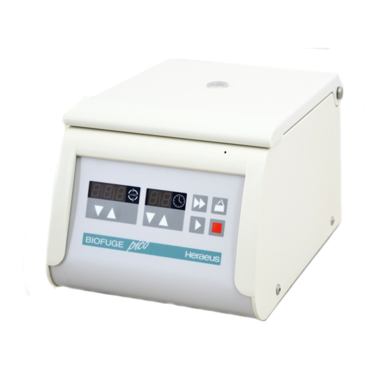
Summary of Contents for Heraeus biofuge pico
- Page 1 Biofuge Instructions for Use...
-
Page 2: How To Use This Manual
How to use this manual Use this manual to get acquainted with your centrifuge and its accessories. The manual helps you to avoid inappropriate handling. Overleaf you will find a graphic Make sure to keep it always close to the centrifuge. representation of the control panel with a survey of the most important A manual that is not kept handy cannot provide... - Page 3 speed quick run time rotor turns open lid stop start "set" keys back panel: socket for mains connection mains switch...
- Page 4 The control panel of the "Set" keys: stepwise increase/decrease of preset values, accelerated change when pres- Biofuge pico sed permanently Display Short pressing of any of the "set" keys: switch from current to preset value Speed Resting state: preselected speed During run: current speed;...
-
Page 5: Table Of Contents
Conformity to current standards....... 5 Removing the rotor..........22 Safety instructions in this manual ......5 Loading the rotor ............ 22 The Biofuge pico ........7 Maximum loading ..........22 Safety systems............7 Filling the centrifuge tubes ......... 23 Properties..............8 Aerosol-tight application......... - Page 6 Contents Maintenance and care ......31 Maintenance to be performed by the customer ..31 Cleaning.............. 31 Disinfection ............32 Decontamination..........34 Autoclaving ............35 Check whether autoclaving is permitted! ... 35 The Service of KENDRO........36 Warranty conditions ..........36 Troubleshooting ........
-
Page 7: For Your Safety
For your safety For your safety Proper use The centrifuge is designed to separate liquid- Heraeus centrifuges are manufactured according to suspended materials having different densities and current technical standards and regulations. Nonethe- particle size, respectively. The maximum sample den- less, centrifuges may pose dangers if sity is 1.2 g/cm... -
Page 8: Handling
For your safety • Do not centrifuge toxic or radioactive substances or • Changes in mechanical or electrical components pathogenic microorganisms unless you have taken may be carried out only by persons authorized to proper precautions. this effect by KENDRO Laboratory Products. •... -
Page 9: Conformity To Current Standards
For your safety Conformity to current standards Safety instructions in this manual Heraeus centrifuges are manufactured and tested This symbol denotes potential hazards to according to the following standards and regulations: persons. This symbol denotes potential damage to for all voltages: the centrifuge or parts in its immediate sur- •... - Page 10 For your safety for your notes...
-
Page 11: The Biofuge Pico
The Biofuge pico The Biofuge pico Safety systems The Biofuge pico is equipped with a number of safety The figure below shows the Biofuge pico with the lid systems. opened and the rotor put in place. • Connection rotor – motor •... -
Page 12: Properties
The Biofuge pico Properties „Quick run“ operation The Biofuge pico is a benchtop centrifuge for use in the As long as the "quick run" key ( ) is pressed, the ro- biochemical and medical laboratory. tor is accelerated with maximum power, potentially up to the maximum speed (overriding any preset speed The preset speed is reached in seconds. -
Page 13: Pieces Delivered
The Biofuge pico Pieces delivered The Biofuge pico is delivered complete with: • a special cap nut for fixing the rotor • 10-mm tubular socket wrench for fastening the cap nut • fixed-angle rotor 24 x 1,5 / 2 ml 7500 3328 •... - Page 14 The Biofuge pico for your notes...
-
Page 15: Accessories
Accessories Accessories The Biofuge pico is delivered complete with a fixed- angle rotor with 24 holes for placing microliter tubes with a volume of 1.5 or 2.0 ml. In addition you may order three sets of adapters con- taining 24 reduction sleeves each. With these adapters you can centrifuge all commercially available microliter tubes with a volume between 0.2 and 0.6 ml as well as... -
Page 16: Rotor Program
Accessories Rotor program Rotor designation Microliter rotor PCR-rotor 24 x 2 ml PP order no. 7500 3328 7500 3327 places / volume 24 x 1,5 / 2 ml 4 x PCR-Strip maximum permissible load [ g ] 24 x 4 4 x 4 ( 32 x 0,5 ) maximum speed n... -
Page 17: Adapters For Rotor Order No. 7500 3328
Accessories Adapters for rotor order no. 7500 3328 Adapter Dimensions Capacity Number per Color Order No. (∅ x H) reduction sleeve PCR 6,2 x 20 mm 0,2 ml gray 7600 3750 reduction sleeve 8 x 43,5 mm 0,5/0,6 ml turquoise 7600 3758 reduction sleeve 6 x 46 mm... - Page 18 Accessories for your notes...
-
Page 19: Before Use
• The location should be well ventilated. and remove the transport protection for the rotor. Check that the rotor moves freely by lightly turning it, and make sure the rotor is tightly screwed on. The Biofuge pico is now ready for use. - Page 20 Before use for your notes...
-
Page 21: Operation
Operation Operation Transport and installation type plate with voltage and frequency Damage to the centrifuge by jolts or jerky placement! mains switch Transport the centrifuge only in the upright position using the special socket for mains box provided with the instrument cable and secure it properly. -
Page 22: Opening The Lid
Operation In this example, the pre- Emergency lid release set speed is 5,000 rpm In case of a power failure you cannot open the lid nor- and the preset run time mally using the "open lid" key. To permit unloading is 10 min. - Page 23 Operation upper right of the front panel (see figure). Push the lock bolt back until the lid unlocks audibly. Remove the auxiliary tool and open the lid. 4. In case the rotor still turns, close lid immediately and wait until it has come to a complete stop. Emergency lid release Never brake the rotor using your...
-
Page 24: Inserting The Rotor
2. Turn the rotor so that the notch for engaging the Rotors which are allowed for use in a Biofuge pico cen- drive shaft points downward. trifuge are detailed in the chapter "Accessories", and 3. Place the rotor on top of the drive shaft so that the only these rotors are to be used in this centrifuge. -
Page 25: Permissible Rotor Temperature
Operation 5. If you have placed the rotor correctly, you can Permissible rotor temperature screw on the cap nut easily and secure it with the tubular socket wrench delivered with the instrument. The rotors are only to be used within the temperature range from - 6. -
Page 26: Removing The Rotor
The Biofuge pico can reach high rotational speeds im- Danger of irreparable motor damage! plying enormous centrifugal force. The rotors are de- signed in a way warranting sufficient residual strength Never tilt the rotor. -
Page 27: Filling The Centrifuge Tubes
Operation Filling the centrifuge tubes Please note that plastic sample vessels only have a limited service life - particularly when used at maximum rpm or temperature - and Check carefully whether your sam- must be replaced as necessary! ple vessels are permissible for the respective g value and reduce the speed if necessary. -
Page 28: Aerosol-Tight Application
Operation Aerosol-tight application Attention : Please check that your sample containers are suitable for the centrifugal application desired. not with open container lids! (16060 x g ; temperature in uncooled devices approx. 10 K above room temperature) The following steps have to be carried out: Please observe the permissible filling volumes! •... -
Page 29: Checking For Aerosol Tightness
Operation • Checking for aerosol tightness Check the paper strip under UV light (preferentially in a darkened room): If there is no detectable fluorescence, the test is Check the aerosol tightness of your considered passed. rotor whenever appropriate. • Finally rinse rotor, rotor lid and lid seal in running water and allow to dry. -
Page 30: Placing The Tubes In The Rotor
Operation Placing the tubes in the rotor Improper loading can in the worst The rotor must be loaded symmetrically. When loading case lead to damage to rotor and the rotor only partially, you must ensure that opposite centrifuge. Unbalance only bores always receive tubes of equal weight (when cen- causes a noisy run, but rapidly trifuging a single sample, place a centrifuge tube e.g. -
Page 31: Selecting The Speed
Operation Selecting the speed Selecting the run time The centrifuge can be set to a minimum of 2000 min You can select a run time between 1 and 99 min or and to a maximum of 13 000 min . The built-in micro- continuous operation. -
Page 32: Continuous Operation
Operation Continuous operation Changing the settings during the run To operate the Biofuge pico in the continuous mode, You can change the settings during a run. The respec- you must press the key until the display changes to tive altered setting flashes for a couple of seconds. -
Page 33: Short-Time Centrifugation
Operation Short-time centrifugation RCF value For short-term operation, the Biofuge pico is equipped The relative centrifugal force (RCF) is usually given in with a "quick run" function. multiples of the earth gravity g. It is a dimensionless number that allows one to compare the efficiency of... - Page 34 Operation The figure for the maximum RCF value is based on the maximum radius of the tube. Please note that this value becomes lower depending on the tubes and adapters used. You may take this into account when calculating the RCF value for your application.
-
Page 35: Maintenance And Care
Maintenance and care Maintenance and care Cleaning Maintenance to be performed by the Pull mains plug before cleaning the customer instrument! For the protection of persons, environment and mate- rial you are obliged to clean the centrifuge regularly Clean the casing, the rotor chamber, the rotor and the and to disinfect it if necessary. -
Page 36: Disinfection
Maintenance and care Disinfection If a centrifuge tube containing infectious material leaks During cleaning liquids and espe- during a run, you have to disinfect the centrifuge im- cially organic solvents should not mediately. come into contact with the drive shaft and the ball bearing. Organic solvents may decompose Infectious material could enter the centri- the lubricant of the motor bearing. - Page 37 Maintenance and care Rotor and rotor chamber must be treated with a neu- • You may disinfect the rotor and the accessories as tral, universal disinfectant. Best suited for this purpose described in the following section. Be sure to follow are disinfectant sprays, ensuring that all rotor and ac- the pertinent safety procedures for handling infec- cessory surfaces are covered evenly.
-
Page 38: Decontamination
Maintenance and care Disinfection with bleaching lye Decontamination For general radioactive decontamination, use a solu- These agents contain highly aggres- tion of equal parts of 70% ethanol, 10% SDS and wa- ter. Follow this with ethanol rinses, then de-ionized wa- sive hypochlorites and must not be ter rinses, and dry with a soft absorbent cloth. -
Page 39: Autoclaving
Maintenance and care Autoclaving Check whether autoclaving is permitted! Never exceed the maximum permis- sible values for autoclaving tem- You may autoclave the rotor and the adapters at perature and autoclaving time. 121 °C. Should the rotor show signs of Maximum permissible autoclaving cycle: wear, you must stop using it! 20 min at 121 °C. -
Page 40: The Service Of Kendro
Maintenance and care The Service of KENDRO Warranty conditions Kendro Laboratory Products recommends annual ser- The warranty period starts with the day of delivery. vicing of the centrifuge and the accessories by the au- Within the warranty period the centrifuge is repaired or thorized service or skilled personnel. -
Page 41: Troubleshooting
Troubleshooting Troubleshooting Problems you can handle yourself If problems other than those described in the following tables arise, you must consult your nearest authorized service. Error Behavior of the centrifuge Possible cause(s) and measures to be taken Displays remain The motor stops. Mains failure or not connected dark The rotor stops without braking. - Page 42 Troubleshooting Error Behavior of the centrifuge Possible cause(s) and measures to be taken Lid cannot be Pressing the "open lid" key has A) Lid not correctly engaged or lid warped. opened no effect 1. Check whether the mains supply is OK and the instrument is switched on (displays lit).
- Page 43 Troubleshooting Error Behavior of the centrifuge Possible cause(s) and measures to be taken Motor does not start Motor or rotor blocked. 1. Switch the instrument off and on again with the mains switch. 2. Open the lid. 3. Check whether the transport protection has been removed. If you cannot solve the problem, call nearest Service.
- Page 44 Troubleshooting Error Behavior of the centrifuge Possible cause(s) and measures to be taken Message "Lid" Motor stops. A) The lid was manually opened during the run. appears in the Rotor comes to a stop without 1. Press the lid shut. The instrument comes to a stop without display braking.
- Page 45 Troubleshooting...
-
Page 46: In Case You Must Call The Service
Troubleshooting In case you must call the Service Software number Should you require our Service, please tell us the order no. and serial number of the instrument. You find the Software version pertinent information at the back of the instrument near NV-RAM number the socket for the mains plug. - Page 47 Troubleshooting for your notes...
-
Page 48: Technical Data
Technical data Technical data Component parts and performance Part / function Description Body Sheet steel with fitted plastic chassis Keys and display panel Keys and display panel covered with easy care protective foil Operation "Easycontrol" system Rotor chamber Dimensions (diameter x height): 188 mm x 63 mm Rotor chamber Up to 48 ml of spilled liquids are retained in the rotor chamber and cannot enter the instrument. - Page 49 Technical data Function / parameter Value environmental conditions indoor use max. elevation 2000 m above sea level max. relative humidity 80 % up to 31 °C; linearly decreasing down to 50 % relative humidity at 40 °C. Permissible temperature of the environment +2 °C to +40 °C Maximum speed n 13 000 min...
- Page 50 Technical data...
-
Page 51: The "Easycontrol" User Interface
Technical data The "Easycontrol" user interface Function Performance Start Start key ( Stop Stop key ( Short-term start and stop, respectively „Quick run“ key ( ): short-term run when pressed permanently; stop when released Mode of operation display Turning rotor is signalled by rotating light (LED display) in the speed pa- nel. - Page 52 Technical data Function Performance Parameter memory • speed • time Function Performance Diagnostic messages • lid not properly closed: display „OP“ • general malfunction (ERROR Codes, see page 37) Testing standards 230V instruments Manufactured and tested in accordance with EN 61 010-1, EN 61 010-2-020 EN 61326 (+ EN 61000-3-2/A14:2000-6) EN 55011 B 120 / 100V instruments...
-
Page 53: Electrical Connections / Fuses
Technical data Electrical connections / fuses Order no. Voltage Frequency Nominal current Power consumption Fuses inside instrument * 7500 3235 230 V 50/60 Hz 1,1 A 150 W 2 x 2 A slow-blow (5 x 20 mm) 7500 3236 110/120 V 60 Hz 150 W 2 x 4 A slow-blow... - Page 54 Technical data for your notes...
-
Page 55: Index
Index Index during run 28 cleaning 31 conditions of warranty 36 contamination necessary measures 32 acceleration 8 continuous operation 28 accessories control panel cap nut 9 readings 8 rotor 11 corrosive substances tubular socket wrench 9 protective vessels for 4 aerosol tightness cycle counter 46 check 25... - Page 56 Index fuses 47 EC Guidelines 5 electrical connections 47 emergency lid release 7 hazardous substances 3 emergency release hazards lid 7 symbols used for 5 error messages hints „br“ 38 symbol for 5 „E-0“ 39 „E-10“ 39 „E-11“ 39 „E-8“ 39 „lid 40 „OP“...
- Page 57 Index general operation 8 opening the lid 18 operation continuous 28 preselected run time 27 blockage 38 short-time 29 lid lock mechanism 7 organic solvents lid open during run not allowed for cleaning 32 warning 7 original parts lid opening 18 mandatory use 4 lid release overloading...
- Page 58 Index quick run function 29 safety instructions 3, 4 quick run key 8 safety measures 3 safety standards 5 safety systems built-in 7 safety zone 3 30 cm around centrifuge 15 radius of centrifugation sample density for calculation of RCF value 29 maximum 3 RCF value 29 service contracts 36...
- Page 59 Index stopping 28 volume range 11 substructure 15 symbols for hazards and dangers 5 unbalance 23 temperature of the environment permissible 44 temperature range for rotor voltage 15 permissible 44 toxins protection against 4 transport precautions for 17 warning tube lid open during run 7 breakage with infectious material 32 warranty conditions 36...
- Page 60 Index...
-
Page 61: Autoclaving Protocol
Autoclaving protocol Autoclaving protocol Date Remark Operator Signature... -
Page 62: Speed / Rcf Diagrams
Speed / RCF diagrams for PCR-Rotor 7500 3327 100000 13000 10000 1000 = 4,7 cm = 6,8 cm 1000 10000 100000 12846 RCF [x g]... - Page 63 Speed / RCF diagrams for 24 x 2ml Rotor 7500 3328 100000 13000 10000 1000 = 5,9 cm = 8,5 cm 1000 10000 100000 16060 RCF [x g]...
- Page 65 Heraeus S.A. · Massamá · Tel. +351 (0) 214-387 630 · Fax +351 (0) 214-387 636 · heraeus@mail.telepac.pt Spain Heraeus S.A. · Madrid · Tel. +34 (0) 91-358 19 96 · Fax +34 (0) 91-358 20 67 · laboratorio@heraeus.es Sweden Axeb AB ·...
Need help?
Do you have a question about the biofuge pico and is the answer not in the manual?
Questions and answers