Table of Contents
Advertisement
Advertisement
Table of Contents

Summary of Contents for Teseq NSG 437
- Page 1 NSG 437 ESD SIMULATOR USER MANUAL 601-272C...
- Page 2 NSG 437 ESD SIMULATOR USER MANUAL 601-272C NSG 437 ESD simulator...
-
Page 3: Table Of Contents
CONTENTS Explanation of the symbols used in this manual Safety Introduction of ESD phenomenon Electrostatic discharge (ESD) Simulation Effects on the EUT NSG 437 The simulator 4.1.1 Function modules 4.1.2 Block diagram 4.1.3 Operating elements System components 4.2.1 Power supply unit 4.2.2... - Page 4 Maintenance 10.1 Calibration 10.2 Exchanging the R / C network 10.2.1 Reduction of pulse repetition rate through higher capacity 10.3 Repairs 10.4 NSG 437 system error messages 10.5 Disposal 10.6 Declaration of conformity CE Technical specifications ESD standards Warranty Accessories Addresses...
-
Page 5: Explanation Of The Symbols Used In This Manual
1 EXPLANATION OF THE SYMBOLS USED IN THIS MANUAL Please take note of the following explanations of the symbols used in order to achieve the optimum benefi t from this manual and to ensure safety during operation of the equipment. The following symbol draws your attention to a circumstance where non- observation of the warning could lead to inconvenience or impairment in the performance. -
Page 6: Safety
The NSG 437 simualtor is not a toy! It is a professional tool and belongs only in the hands of specialists and appropriately trained personnel. The instrument must not be switched on unless a correctly connected earth or earth cable (pulse current return path) is in place. - Page 7 The instrument‘s housing and the cable have both an insulating and a screen- ing function, which can only be assured while the housing is intact. Return a damaged simulator to a Teseq service centre immediately for repair. Teseq Luterbach, Switzerland and the associated sales organization accept no responsibility for personal or material damage nor for any consequential damage that results from irresponsible operation of this instrument.
-
Page 8: Introduction Of Esd Phenomenon
The high equalizing current that fl ows, and the associated large electromagnetic fi eld that hence results, can cause electronic devices (computers, terminals, process controllers, vehicle electronics, solid state devices, credit or memory cards, etc.) to malfunction or even be destroyed. NSG 437 ESD simulator... -
Page 9: Simulation
3.2 Simulation A systematic investigation of electronic equipment and installations to deter- mine their electromagnetic compatibility (EMC) is, today, a necessity if one is not prepared to suffer the economic disadvantages that could otherwise ensue. As a logical consequence, appropriate testing is now a legal requirement for the sale of electronic products within the EU. - Page 10 The ESD simulator NSG 437 fulfils the requirements of numerous applications in an ideal manner, thus: Ergonomic shape For non-tiring use Operation Operating elements and display always in view of the user. Constant check on the test values. Microprocessor- All the functions are ”on-board”, including a pre-...
-
Page 11: Effects On The Eut
ESD testing usually shows up all the weak spots in the HF-range of a piece of equipment simultaneously. The uses to which the NSG 437 ESD simulator can be put hence go way beyond those called for in standard-conform applications. -
Page 12: Nsg 437
Both the operating elements and the display window remain in view of the user while work is in progress. NSG 437 offers optimal freedom of movement around the workplace and is an ideal test instrument not just for the development engineer but also for quality control purposes, system tests and for investigations in the field. -
Page 13: The Simulator
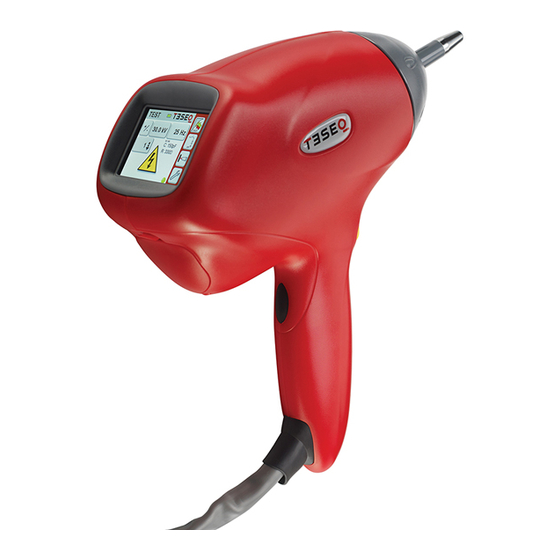
4.1 The simulator The NSG 437 simulator is modularly constructed from a number of discrete function units. 4.1.1 Function modules The base station contains the high voltage generator. Base station Pistol Display and touch-panel Discharge network (exchangeable) on / off... -
Page 14: Block Diagram
The various function units are shown in the block diagram: Block diagram of the base station: High voltage active µP control unit Buzzer Communication to Meas. discharge pistol circuit High voltage generator + / - High voltage to discharge pistol Power on Power NSG 437 ESD simulator... - Page 15 Block diagram of the pistol: Display with touch - panel Buzzer µP control unit Discharge High voltage network relay The microprocessor controls and monitors all the simulator functions: Touch-panel entries are checked for plausibility. Unacceptable entries are rejected and an acoustic warning notifies the user of the error. Values entered are clearly shown on the large display screen.
-
Page 16: Operating Elements
NSG 437 is switched on and off with the power button. Further information can be found in section "Operation". All operations are performed via touch-panel. -
Page 17: System Components
4.2 System components The basic ESD simulator set NSG 437 includes: Pistol Base station Discharge network 150 pF / 330 Ω / IEC / EN 61000-4-2 (2001) 1 test finger for air-discharges 1 test finger for contact-discharges Power supply unit... -
Page 18: Discharge Networks
Networks conforming to other standards can be built upon request. The specifications of the standard must be fully defined. Exchanging the discharge network is described in section "Exchanging the R / C network". NSG 437 ESD simulator... -
Page 19: Measurement Adapters
4.2.4 Measurement adapters The measurement adapter type MD 101 as per IEC / EN 61000-4-2 (2001) serves to verify pulse amplitudes and pulse shapes. It is designed for mounting in the side wall of a Faraday cage in which an oscilloscope has been installed. This measurement adapter has the flat impedance curve to well over 1 GHz that is necessary for the purpose. -
Page 20: Commissioning
Before putting the instrument into operation: Study the manual Take the necessary safety precautions Connect the earth cable correctly (NSG 437 must never be switched on without a solid earth connection being made) Allow the instrument to dry out if any condensation has occurred 5.1 Function test... - Page 21 High voltage generation is activated by pushing the trigger button and keeping it depressed. By bringing the test finger close to the earthing point an arc discharge occurs which is acknowledged acoustically and the display shows the preset discharge voltage in a frame.
-
Page 22: Operation
6 OPERATION This section of the manual provides a guide through the numerous operating possibilities of the NSG 437. The operation hierarchically arranged, is therefore easy to remember. The display shows unmistakable information about the parameters that have been set and the operating status of the simulator. Equally, the instrument refuses to accept any invalid entries. -
Page 23: Operation And Settings
The instrument is ready for use immediately after self-test and calibration pro- cedures have been completed. High voltage generation is activated by pressing and holding the trigger button. The active high voltage state is indicated on the base station by a blinking red LED. Should a parameter need changing the operator has only to press on the rel- evant field in order to call up the appropriate menu. -
Page 24: Display
Preset counter on / off. In the "on" state the counter content can be set. When the generator is in operation the preset counter counts down until it reaches 0, which then terminates the selected test sequence. NSG 437 ESD simulator... - Page 25 To use the continous operation mode the preset counter has to be switched off and the number has to be 0. - - - - means continuous operation without any preset counter function. Pressing the trigger button starts the generator operating;...
-
Page 26: Repetition
Changing the relevant test parameters will cause a new entry into the log to be created. The Log is in volatile RAM and will be reset each time the gun is switched off! NSG 437 ESD simulator... -
Page 27: Threshold
6.3.4 Threshold This function permits to switch the threshold to "normal" or "off". Normal: Arcing is detected and is indicated by the kV symbol on the display blinking provided 20% (or more) of the charge voltage is dissi- pated. Off: This means in contact-discharge mode, the arcing detection is disregarded and the counter counts up / down as per settings in the repetition or counter menu respectively. -
Page 28: Continuous Operation
ESD radiates electro- magnetic disturbance the effect of which on the environment must be taken into consideration. The test area should be made out of bounds for unauthorized personnel. The test must be monitored throughout its duration. NSG 437 ESD simulator... -
Page 29: Test Procedures
EUT itself and the documentation. 7.1 Standard-compliant procedures The ESD simulator system type NSG 437 is constructed in accordance with the requirements called for in the standard and is calibrated in a standard-conform manner. - Page 30 Earth connection Base station Bleeder resistor Earth wire Insulation Example of test set-up for floor-standing equipment – laboratory tests Cabinet earthed via protective earth Mains connection Base station Earth connection Insulation pallet Earth wire Ground reference plane NSG 437 ESD simulator...
-
Page 31: Verification Of The Pulse Data
The calibration and verifi cation of the pulse data requires a specialist test and measurement laboratory for which the IEC standard sets out certain minimal requirements. Teseq uses the following instruments for calibration purposes: Oscilloscope with an analogue bandwidth of min. 1 GHz Coaxial measurement adapter MD 101 Pellegrini-target as per IEC / EN 61000-4–2 (2001) or MD 103 according to latest draft... -
Page 32: Typical Pulse Data
0.8 ns) current at 30 ns and 60 ns Reference fi gure quoted in IEC / EN 61000-4-2 (2001) 100% I at 30 ns I at 60 ns 30 ns 60 ns = 0.7 to 1.0 ns NSG 437 ESD simulator... -
Page 33: Maintenance
The instrument contains no fuses that are accessible to the user. 10.1 Calibration Trimming procedures in the NSG 437 are carried out digitally and automatically. The instrument contains no elements that are foreseen for adjustment by the user. A component defect must be suspected if the calibration measurements differ from the published technical data and the instrument is to be returned to an authorized Teseq service centre. -
Page 34: Exchanging The R / C Network
These values are valid only for the discharge network that conforms to IEC / EN 61000-4-2. Remark Teseq offers an accredited service for this kind of work! 10.2 Exchanging the R / C network If a network needs to be exchanged, the test has to be stopped first, followed by a waiting time of at least 5 s to ensure the voltage being internally discharged. -
Page 35: Reduction Of Pulse Repetition Rate Through Higher Capacity
No other limiting effects occur, however. 10.3 Repairs Repair work is to be carried out exclusively by an authorized Teseq repair department. Voltages in excess of 30 kV are generated within the instrument: LETHAL DANGER! Only original replacement parts and accessories are to be used. -
Page 36: Nsg 437 System Error Messages
10.4 NSG 437 system error messages Text Explanation Action HV SUPPLY The HV cannot be HV voltage module has detected TIMEOUT loaded in the specified during measurement an uncertain- time. ty. Switch off the base station wait for 10 s, switch on again. -
Page 37: Disposal
1h. 10.5 Disposal The following list shows the principal materials used in the construction of the NSG 437. The relevant national regulations are to be observed when disposing of the instrument. Component material listing Pistol housing... -
Page 38: Declaration Of Conformity Ce
10.6 Declaration of conformity CE NSG 437 ESD simulator... -
Page 39: Technical Specifications
TECHNICAL SPECIFICATIONS Description Compact ESD simulator with microprocessor-based, large touch-sensitive LCD panel, built-in HV relay for contact-discharge, mains operation Basic set Package with: Discharge pistol High voltage base unit Mains power supply adapter (100 to 250 VAC) Discharge network 150 pF / 330 Ω Air- and contact-discharge tips Grounding cable User manual... - Page 40 Counter / preselect counter content Weight Discharge pistol (w / o cable): 1.2 kg (2.6 lbs) approx. Base unit: 5.7 kg (12.6 lbs) approx. Ambient Operation: conditions +5 to +40°C 20 to 80% r.h. (non-condensing) 68 to 106 kPa NSG 437 ESD simulator...
-
Page 41: Esd Standards
ESD STANDARDS The IEC / EN 61000-4-2 standard can be taken as a working basis. This has been renamed from IEC 801-2, 1991 into IEC 1000-4-2 as well as IEC / EN 61000-4-2 (2001) and will be accepted into national standards as part of the European harmonization. -
Page 42: Warranty
WARRANTY Teseq grants a warranty of 2 years on this instrument, effective from the date of purchase. During this period, any defective component part will be repaired or replaced free of charge or, if necessary, the instrument will be replaced by another of equivalent value. -
Page 43: Accessories
ACCESSORIES NSG 437 Basic set (see technical specifi cations) Accessories NSG 437 Part number Discharge network ISO 10605, 150 pF / 2 kΩ INA 4381 Discharge network ISO 10605, 330 pF / 2 kΩ INA 4382 Discharge network ANSI C63.16, 150 pF / 330 Ω... - Page 44 T + 44 845 074 0660 F + 886 2 2917 2626 F + 44 845 074 0656 uksales @ teseq.com taiwansales @ teseq.com © March 2014 Teseq ® Teseq Inc. Specifications subject to change T + 1 732 417 0501 without notice.
Need help?
Do you have a question about the NSG 437 and is the answer not in the manual?
Questions and answers