Advertisement
Manual
Functional inspection
Visual inspection
Inspect lift functions regularly. Check to ensure that material is free from damage.
Always read the instructions
Read instructions for all assistive devices used in connection with transfers.
Keep the instruction manual where it is accessible to users of the product.
Do not leave the patient unattended during a lifting situation.
Before use:
Ensure that the product is correctly assembled.
Ensure that lifting accessories are appropriate in relation to the patient's needs and functional ability.
Check slingbar connection and safety latch function.
Check lifting function and base-width adjustment.
Under no circumstances may the lift be used by persons who have not received instruction in the operation of the lift.
Manual no: 00884En ver. 1 090713
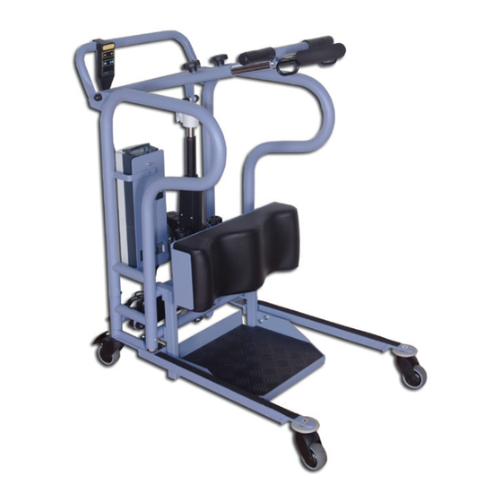
The MiniLift125 is an electric sit-to-stand lift for people with
impaired mobility. For indoor use and in combination with
the right accessories, it is designed to assist a patient com-
fortably and conveniently to a standing position. It provides
support under the feet, against the shins and behind the
back. The MiniLift125 is appropriate for patients who have
a degree of stability while standing. The MiniLift125 helps to
train the patient's leg muscles and sense of balance.
RoMedic's slings and lifts are part of the SystemRoMedic
concept, which takes a holistic approach to patient
transfers. SystemRoMedic has four categories of transfers:
transfer, positioning, support and lifting.
Max load: 125 kg/275 lbs
1 5
Advertisement
Table of Contents

Related Manuals for RoMedic MiniLift125


Summary of Contents for RoMedic MiniLift125
- Page 1 Manual The MiniLift125 is an electric sit-to-stand lift for people with impaired mobility. For indoor use and in combination with the right accessories, it is designed to assist a patient com- fortably and conveniently to a standing position. It provides support under the feet, against the shins and behind the back.
-
Page 2: Table Of Contents
M A N U A L Table of contents Technical information ................Important information ................. Max. load ....................Detailed description ................Assembly instructions for MiniLift125 ............. Dimensions, MiniLift125 ................. Final inspection ..................Operation/trial use ................. Control box and battery features ............ -
Page 3: Technical Information
• MiniLift125must be assembled in accordance with the assembly instructions provided by RoMedic. • Warranty does not apply if repairs or alterations are made by personnel who are not authorized by RoMedic. • Batteries, control unit and actuators on MiniLift125 must not come in direct contact with water. -
Page 4: Max. Load
The lowest allowable maximum load always determines the maximum load of the assembled system. Always check the maximum loads for the lift and accessories before use. Contact RoMedic if you have any questions. Detailed description... - Page 5 M A N U A L Assembly of MiniLift125 Check to ensure that all components are included: Lift unit, control box and battery pack. Undercarriage and base-width adjustment motor. Footrest and leg support. Handset and cord. Instructions, charging cable and power supply cord for charging.
- Page 6 M A N U A L Dimensions All dimensions are in mm. Tolerance +/- 5mm Base (undercarriage) length 870 mm Inner measurement undercarriage min. 430 mm Inner measurement undercarriage max. 750 mm Outer measurement undercarriage min. 590 mm Outer measurement undercarriage max. 890 mm Height 985 mm...
-
Page 7: Final Inspection
M A N U A L Final inspection Inspect the lift for signs of wear and damage. Check all four castor wheels and castor wheel locks. Check all connections and fixtures including screws and bolts. Check the packaging for any loose bolts and screws. -
Page 8: Operation/Trial Use
M A N U A L Operation/trial use Select a lift vest that is the correct size for the patient. Place the lift vest behind the patient’s lower back. Fasten the clasp and tighten the belt. Place the lift close to the patient and place the patient’s feet far in on the footrest. -
Page 9: Charging
M A N U A L The control box and battery have the following features: Emergency stop Electrical emergency lowering Display showing battery charge level Charging cable Outlet for base-width adjustment motor Outlet for lift mast actuator Outlet for handset LED lamp for charging Handle for lifting battery... - Page 10 M A N U A L Emergency stop Emergency stop To activate emergency stop: Press the red emergency stop button on the control box. Resetting: Turn the button in the direction of the arrows until the button pops out. Emergency lowering Mechanical emergency lowering Load must be applied to the slingbar before it can be lowered.
-
Page 11: Trouble-Shooting
Try to locate the source of the sound, take the lift out of operation and contact RoMedic. Other maintenance details: The lift must undergo thorough inspection at least once per year. This must be done by authorized RoMedic service personnel and in accordance with RoMedic’s service manual. - Page 12 “We love easy transfers” RoMedic’s lifts and lifting accessories are part of SystemRoMedic. This means they are part of a holistic approach to lifting and transferring. SystemRoMedic includes four transfer segments: transfer, repositioning, support and lifting. RoMedic’s products are developed on an ongoing basis, which is why we reserve the right to modify product designs without prior notice.
Need help?
Do you have a question about the MiniLift125 and is the answer not in the manual?
Questions and answers