
Related Manuals for Yamaha SR400


Summary of Contents for Yamaha SR400
- Page 1 Read this manual carefully before operating this vehicle. OWNER’S MANUAL SR400 2RD-28199-E0...
- Page 2 EAU46091 Read this manual carefully before operating this vehicle. This manual should stay with this vehicle if it is sold.
- Page 3 Yamaha a reputation for dependability. Please take the time to read this manual thoroughly, so as to enjoy all advantages of your SR400. The Owner’s Manual does not only instruct you in how to operate, inspect and maintain your motorcycle, but also in how to safeguard yourself and oth- ers from trouble and injury.
-
Page 4: Important Manual Information
IMPORTANT MANUAL INFORMATION EAU10134 Particularly important information is distinguished in this manual by the following notations: This is the safety alert symbol. It is used to alert you to potential personal injury hazards. Obey all safety messages that follow this symbol to avoid possible injury or death. - Page 5 IMPORTANT MANUAL INFORMATION EAU10201 SR400 OWNER’S MANUAL ©2013 by Yamaha Motor Co., Ltd. 1st edition, October 2013 All rights reserved. Any reprinting or unauthorized use without the written permission of Yamaha Motor Co., Ltd. is expressly prohibited. Printed in Japan.
-
Page 6: Table Of Contents
TABLE OF CONTENTS SAFETY INFORMATION ....1-1 FOR YOUR SAFETY – Spoke wheels ........ 6-16 PRE-OPERATION CHECKS ..... 4-1 Adjusting the clutch lever free DESCRIPTION ........2-1 play..........6-16 Left view .......... 2-1 OPERATION AND IMPORTANT Adjusting the brake lever free Right view ........ - Page 7 TABLE OF CONTENTS Replacing the fuses ....... 6-29 Replacing the headlight bulb ..6-31 Replacing the tail/brake light bulb ..........6-32 Replacing a turn signal light bulb ..........6-33 Replacing the auxiliary light bulb ..........6-34 Front wheel........6-35 Rear wheel ........6-37 Troubleshooting......
-
Page 8: Safety Information
SAFETY INFORMATION EAU1028B Take a training course. Beginners • Use extra caution when you are should receive training from a cer- approaching passing tified instructor. Contact an autho- through intersections, since in- Be a Responsible Owner rized motorcycle dealer to find out tersections are the most likely As the vehicle’s owner, you are respon- about the training courses nearest... - Page 9 SAFETY INFORMATION tice riding your motorcycle with both hands and keep both control levers, footrests, or wheels where there is no traffic until you feet on the passenger footrests. and cause injury or an accident. have become thoroughly famil- Never carry a passenger unless Always wear protective clothing iar with the motorcycle and all of...
- Page 10 Yamaha accessories, which are avail- to minimize imbalance or instabili- of the motorcycle is changed. To avoid able only from a Yamaha dealer, have the possibility of an accident, use ex- been designed, tested, and approved ...
- Page 11 Yamaha, even if sold and limit suspension travel, steering not recommended. installed by a Yamaha dealer.
- Page 12 SAFETY INFORMATION Check that the fuel cock (if equipped) is in the “OFF” position and that there are no fuel leaks. Point the front wheel straight ahead on the trailer or in the truck bed, and choke it in a rail to pre- vent movement.
-
Page 13: Description
DESCRIPTION EAU10411 Left view 1, 2 5, 6 1. Engine oil dipstick (page 6-9) 2. Engine oil filler cap (page 6-9) 3. Fuel tank cap (page 3-7) 4. Fuel cock (page 3-10) 5. Battery (page 6-28) 6. Fuse (page 6-29) 7. -
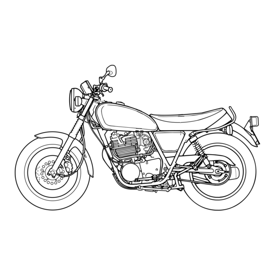
Page 14: Right View
DESCRIPTION EAU10421 Right view 1. Air filter element (page 6-12) 2. Kickstarter (page 3-10) 3. Kick indicator (page 5-1) 4. Headlight (page 6-31) 5. Brake pedal (page 3-6) 6. Owner’s tool kit (page 6-2) 7. Shock absorber assembly spring preload adjusting ring (page 3-12) -
Page 15: Controls And Instruments
DESCRIPTION EAU10431 Controls and instruments 1. Clutch lever (page 3-5) 9. Throttle grip (page 6-13) 2. Left handlebar switches (page 3-4) 10.Decompression lever (page 3-11) 3. Speedometer unit (page 3-3) 4. Main switch/steering lock (page 3-1) 5. Tachometer (page 3-4) 6. -
Page 16: Instrument And Control Functions
INSTRUMENT AND CONTROL FUNCTIONS EAU10462 EAU10662 To lock the steering Main switch/steering lock All electrical systems are off. The key can be removed. EWA10062 WARNING Never turn the key to “OFF” or “LOCK” while the vehicle is moving. Otherwise the electrical systems will LOCK be switched off, which may result in loss of control or an accident. -
Page 17: Indicator Lights And Warning Lights
INSTRUMENT AND CONTROL FUNCTIONS To unlock the steering may cause the battery to discharge. EAU49395 Indicator lights and warning lights 1. Push. 2. Turn. 1. Engine trouble warning light “ ” Push the key in, and then turn it to 2. -
Page 18: Speedometer Unit
If the warning light does not come on initially when the key is turned to “ON”, or if the warning light remains on, have EAU11354 a Yamaha dealer check the electrical Fuel level warning light “ ” circuit. This warning light comes on when the fuel level drops below approximately 2.2 L (0.58 US gal, 0.48 Imp.gal). -
Page 19: Tachometer
INSTRUMENT AND CONTROL FUNCTIONS EAU11882 EAU1234F Right Tachometer Handlebar switches Left 1. Engine stop switch “ ” 2. Hazard switch “ / ” 1. Tachometer 2. Tachometer red zone 1. Dimmer switch “ ” EAU12351 2. Pass switch “ ” The tachometer allows the rider to Pass switch “... -
Page 20: Clutch Lever
INSTRUMENT AND CONTROL FUNCTIONS lights, push the switch in after it has re- tery may discharge. EAU12821 Clutch lever turned to the center position. EAU12501 Horn switch “ ” Press this switch to sound the horn. EAU12661 Engine stop switch “ ”... -
Page 21: Shift Pedal
INSTRUMENT AND CONTROL FUNCTIONS EAU12872 EAU12892 EAU12942 Shift pedal Brake lever Brake pedal 1. Shift pedal 1. Brake lever 1. Brake pedal The shift pedal is located on the left The brake lever is located on the right The brake pedal is on the right side of side of the motorcycle and is used in side of the handlebar. -
Page 22: Fuel Tank Cap
INSTRUMENT AND CONTROL FUNCTIONS EAU13125 EAU13222 Fuel tank cap Fuel Make sure there is sufficient gasoline in To remove the fuel tank cap the tank. EWA10882 WARNING Gasoline and gasoline vapors are extremely flammable. To avoid fires and explosions and to reduce the risk of injury when refueling, follow 1. - Page 23 Gasoline is poisonous and can as well as to the exhaust system. cause injury or death. Handle gaso- Your Yamaha engine has been de- line with care. Never siphon gaso- signed to use regular unleaded gaso- line by mouth. If you should swallow...
-
Page 24: Fuel Tank Breather/Overflow Hose
INSTRUMENT AND CONTROL FUNCTIONS EAU39453 EAU13434 pairable damage to the catalytic Fuel tank breather/overflow Catalytic converter converter. hose This model is equipped with a catalytic converter in the exhaust system. EWA10863 WARNING The exhaust system is hot after op- eration. To prevent a fire hazard or burns: ... -
Page 25: Fuel Cock
INSTRUMENT AND CONTROL FUNCTIONS EAU59490 EAU13651 Fuel cock Kickstarter The fuel cock regulates and filters the fuel supply from the fuel pump to the fuel injector. The fuel cock has two positions: 1. Arrow mark positioned over “OFF” 1. Kickstarter With the lever in this position, fuel will To start the engine, fold out the kick- not flow. -
Page 26: Decompression Lever
INSTRUMENT AND CONTROL FUNCTIONS EAU13701 EAU13961 Decompression lever Seat To remove the seat Remove the bolts, and then pull the seat off. 1. Seat holder 2. Projection 1. Decompression lever 2. Place the seat in the original posi- When this lever is pulled, the exhaust tion, and then tighten the bolts. -
Page 27: Adjusting The Shock Absorber Assemblies
(a). To de- in a possible loss of control. Yamaha’s ignition circuit cut-off crease the spring preload and thereby system has been designed to assist soften the suspension, turn the adjust-... -
Page 28: Ignition Circuit Cut-Off System
INSTRUMENT AND CONTROL FUNCTIONS Yamaha dealer repair it if it does not EAU59340 Ignition circuit cut-off system function properly. The ignition circuit cut-off system (com- prising the sidestand switch, clutch switch and neutral switch) has the fol- lowing functions. ... - Page 29 2. Make sure that the engine stop switch is set to “ ”. stand during this inspection. 3. Turn the key on. If a malfunction is noted, have a Yamaha 4. Shift the transmission into the neutral position. dealer check the system before riding. 5. Push the kick starter lever down.
-
Page 30: For Your Safety - Pre-Operation Checks
• If necessary, add recommended oil to specified level. • Check vehicle for oil leakage. • Check operation. • If soft or spongy, have Yamaha dealer bleed hydraulic system. • Check lever free play. • Adjust if necessary. Front brake •... - Page 31 • Make sure that operation is smooth. • Check throttle grip free play. Throttle grip 6-13, 6-24 • If necessary, have Yamaha dealer adjust throttle grip free play and lubricate cable and grip housing. • Make sure that operation is smooth. Control cables 6-24 •...
-
Page 32: Operation And Important Riding Points
a lean angle sensor to stop the en- understand, ask your Yamaha dealer. The transmission is in the neutral gine in case of a turnover. In this EWA10272 position. -
Page 33: Starting Trouble
OPERATION AND IMPORTANT RIDING POINTS Yamaha dealer to check the elec- EAU59470 EAU16672 Starting trouble Shifting trical circuit. If the engine fails to start after 4 to 5 3. Completely close the throttle and kicks, clear out the combustion cham- apply the decompression lever. -
Page 34: Tips For Reducing Fuel Consumption
OPERATION AND IMPORTANT RIDING POINTS ECA10261 EAU16811 EAU16842 Tips for reducing fuel Engine break-in NOTICE consumption There is never a more important period Even with the transmission in in the life of your engine than the period Fuel consumption depends largely on the neutral position, do not between 0 and 1600 km (1000 mi). -
Page 35: Parking
Do not park on a slope or on soft Yamaha dealer check the vehi- ground, otherwise the vehicle cle. may overturn, increasing the risk of a fuel leak and fire. -
Page 36: Periodic Maintenance And Adjustment
– possibly leading to pending on the weather, terrain, geo- that is certified (if applicable). Yamaha death. See page 1-2 for more in- graphical location, and individual use, dealers are trained and equipped to... -
Page 37: Owner's Tool Kit
If you do not have the tools or experi- 1. Unlock. ence required for a particular job, have 2. Lock cover a Yamaha dealer perform it for you. 1. Owner’s tool kit The owner’s tool kit is located inside the tool box. -
Page 38: Periodic Maintenance Chart For The Emission Control System
From 50000 km (30000 mi), repeat the maintenance intervals starting from 10000 km (6000 mi). Items marked with an asterisk should be performed by a Yamaha dealer as they require special tools, data and technical skills. EAU46911 Periodic maintenance chart for the emission control system... -
Page 39: General Maintenance And Lubrication Chart
PERIODIC MAINTENANCE AND ADJUSTMENT EAU1770K General maintenance and lubrication chart ODOMETER READING ANNUAL ITEM CHECK OR MAINTENANCE JOB 1000 km 10000 km 20000 km 30000 km 40000 km CHECK (600 mi) (6000 mi) (12000 mi) (18000 mi) (24000 mi) Air filter element •... - Page 40 PERIODIC MAINTENANCE AND ADJUSTMENT ODOMETER READING ANNUAL ITEM CHECK OR MAINTENANCE JOB 1000 km 10000 km 20000 km 30000 km 40000 km CHECK (600 mi) (6000 mi) (12000 mi) (18000 mi) (24000 mi) • Check bearings for looseness or ...
- Page 41 PERIODIC MAINTENANCE AND ADJUSTMENT ODOMETER READING ANNUAL ITEM CHECK OR MAINTENANCE JOB 1000 km 10000 km 20000 km 30000 km 40000 km CHECK (600 mi) (6000 mi) (12000 mi) (18000 mi) (24000 mi) • Change. ...
-
Page 42: Removing And Installing The Panel
PERIODIC MAINTENANCE AND ADJUSTMENT EAU59460 EAU19152 Removing and installing the Panel A panel To remove the panel The panel shown needs to be removed Remove the bolt, and then pull the pan- to perform some of the maintenance el off as shown. jobs described in this chapter. -
Page 43: Checking The Spark Plug
0.7–0.8 mm (0.028–0.031 in) ating improperly. Do not attempt to diagnose such problems yourself. In- To install the spark plug stead, have a Yamaha dealer check 1. Spark plug cap 1. Clean the surface of the spark plug the vehicle. -
Page 44: Engine Oil And Oil Filter Element
PERIODIC MAINTENANCE AND ADJUSTMENT spark plug wrench, and then tight- EAU59622 ing the oil filler cap. [EWA17640] Engine oil and oil filter en it to the specified torque. element The engine oil should be between the Tightening torque: The engine oil level should be checked minimum and maximum level marks. - Page 45 PERIODIC MAINTENANCE AND ADJUSTMENT To change the engine oil (with or 6. Remove the oil filter element drain without oil filter element replace- bolt to drain the oil from the oil filter ment) element. 1. Start the engine, warm it up for several minutes, and then turn it Skip steps 7–9 if the oil filter element is off.
- Page 46 PERIODIC MAINTENANCE AND ADJUSTMENT tem have cooled down. Tightening torque: Oil filter element cover bleed bolt: ECA11621 5 Nm (0.5 m·kgf, 3.6 ft·lbf) NOTICE In order to prevent clutch slip- 13. Install the engine oil drain bolts page (since the engine oil also and their new gasket, and then lubricates the clutch), do not tighten the bolts to the specified...
-
Page 47: Replacing The Air Filter Element
Replace the air filter element so it will not seize. If this occurs, more frequently if you are riding in un- have a Yamaha dealer repair the usually wet or dusty areas. vehicle. ... -
Page 48: Checking The Engine Idling Speed
To prevent this necessary, have it corrected by a from occurring, the valve clearance Yamaha dealer. must be adjusted by a Yamaha dealer Engine idling speed: at the intervals specified in the periodic 1200–1400 r/min maintenance and lubrication chart. -
Page 49: Tires
* Total weight of rider, passenger, car- glass fragments in it, or if the sidewall is go and accessories Operation of this vehicle with im- cracked, have a Yamaha dealer re- proper tire pressure may cause se- place the tire immediately. EWA10512... - Page 50 After extensive tests, only the tires list- and brake-related parts, includ- ed below have been approved for this ing the tires, should be left to a model by Yamaha Motor Co., Ltd. Yamaha dealer, who has the necessary professional knowl- edge and experience.
-
Page 51: Spoke Wheels
4. Clutch lever free play adjusting bolt ride. If any damage is found, have The clutch lever free play should mea- a Yamaha dealer replace the sure 5.0–10.0 mm (0.20–0.39 in) as wheel. Do not attempt even the shown. Periodically check the clutch le- smallest repair to the wheel. -
Page 52: Adjusting The Brake Lever Free Play
After adjusting the brake lever clutch does not operate correctly, have free play, check the free play a Yamaha dealer check the internal and make sure that the brake is clutch mechanism. working properly. ... -
Page 53: Adjusting The Brake Pedal Height And Free Play
2. Brake pedal height adjusting bolt WARNING pedal free play and, if necessary, adjust 3. Tighten the locknut. it as follows. It is advisable to have a Yamaha EWA11232 To increase the brake pedal free play, dealer make these adjustments. WARNING turn the brake pedal free play adjusting nut at the brake rod in direction (a). -
Page 54: Checking The Shift Pedal
Checking the shift pedal Brake light switches The operation of the shift pedal should be checked before each ride. If opera- tion is not smooth, have a Yamaha dealer check the vehicle. 1. Brake pedal free play adjusting nut EWA10681 1. -
Page 55: Checking The Front Brake Pads And Rear Brake Shoes
To check the brake pad wear, check the wear limit line, have a Yamaha Insufficient brake fluid may al- the wear indicator grooves. If a brake... -
Page 56: Changing The Brake Fluid
Clean the filler cap before re- brake system for leakage. If the brake Have a Yamaha dealer change the moving. Use only DOT 4 brake fluid level goes down suddenly, have a brake fluid at the intervals specified in fluid from a sealed container. -
Page 57: Drive Chain Slack
50 N (5.0 kgf, 11 lbf). 6. Brake torque rod To adjust the drive chain slack 4. Measure drive chain slack as Consult a Yamaha dealer before ad- 3. Loosen the drive chain puller lock- shown. justing the drive chain slack. -
Page 58: Cleaning And Lubricating The Drive Chain
PERIODIC MAINTENANCE AND ADJUSTMENT gine as well as other vital parts down. EAU23026 Cleaning and lubricating the of the motorcycle and can lead 7. Tighten both drive chain puller drive chain to chain slippage or breakage. locknuts, and then tighten the axle To prevent this from occurring, nut and brake torque rod nut to The drive chain must be cleaned and... -
Page 59: Checking And Lubricating The Cables
Yamaha dealer at the intervals speci- ed if necessary. If a cable is damaged fied in the periodic maintenance chart. -
Page 60: Checking And Lubricating The Brake And Clutch Levers
PERIODIC MAINTENANCE AND ADJUSTMENT EAU23144 Clutch lever EAU23184 Checking and lubricating the Checking and lubricating the brake and clutch levers brake pedal The operation of the brake and clutch The operation of the brake pedal levers should be checked before each should be checked before each ride, ride, and the lever pivots should be lu- and the pedal pivot should be lubricat-... -
Page 61: Checking And Lubricating The Centerstand And Sidestand
The operation of the centerstand and The swingarm pivots must be lubricat- sidestand should be checked before ed by a Yamaha dealer at the intervals each ride, and the pivots and met- specified in the periodic maintenance al-to-metal contact surfaces should be and lubrication chart. -
Page 62: Checking The Front Fork
2. Hold the lower ends of the front have a Yamaha dealer check or re- tion. WARNING! To avoid injury, fork legs and try to move them for- pair it. -
Page 63: Checking The Wheel Bearings
WARNING To charge the battery Electrolyte is poisonous and Have a Yamaha dealer charge the bat- dangerous since it contains sul- tery as soon as possible if it seems to furic acid, which causes severe have discharged. Keep in mind that the burns. -
Page 64: Replacing The Fuses
PERIODIC MAINTENANCE AND ADJUSTMENT if the vehicle is equipped with optional ECA16531 EAU59441 Replacing the fuses NOTICE electrical accessories. The main fuse is located inside the bat- ECA16522 Always keep the battery charged. NOTICE tery coupler. (See page 6-28.) Storing a discharged battery can To charge a VRLA (Valve Regulated cause permanent battery damage. - Page 65 3. Ignition fuse 4. Disconnect the battery coupler. 10. If the fuse immediately blows 4. Backup fuse again, have a Yamaha dealer 5. Fuel injection system fuse check the electrical system. 6. Parking lighting fuse The fuse box, which contains the fuses 7.
-
Page 66: Replacing The Headlight Bulb
5. If a fuse immediately blows again, cohol or thinner. have a Yamaha dealer check the Headlight lens electrical system. Do not affix any type of tinted film or stickers to the headlight lens. -
Page 67: Replacing The Tail/Brake Light Bulb
2. Remove the burnt-out bulb by 6. Install the headlight unit by install- ing the screws. pushing it in and turning it counter- 7. Have a Yamaha dealer adjust the clockwise. headlight beam if necessary. 1. Headlight coupler 2. Headlight bulb cover 3. -
Page 68: Replacing A Turn Signal Light Bulb
PERIODIC MAINTENANCE AND ADJUSTMENT EAU60010 Replacing a turn signal light bulb 1. Remove the turn signal light lens, turn signal light rim and gasket by removing the screws. 1. Tail/brake light bulb 1. Turn signal light lens 2. Turn signal light rim 3. -
Page 69: Replacing The Auxiliary Light Bulb
PERIODIC MAINTENANCE AND ADJUSTMENT EAU33416 2. Remove the socket (together with Replacing the auxiliary light the bulb) by pushing it in and turn- bulb ing it counterclockwise. If the auxiliary light bulb burns out, re- place it as follows. 1. Remove the headlight unit by re- moving the screws. -
Page 70: Front Wheel
PERIODIC MAINTENANCE AND ADJUSTMENT 4. Insert a new bulb into the socket, EAU24361 Front wheel push it in, and then turn it clock- wise until it stops. EAU59600 5. Install the socket (together with the bulb) by pushing it in and turning it clockwise until it stops. - Page 71 PERIODIC MAINTENANCE AND ADJUSTMENT 6. Pull the wheel axle out, and then legs. axle holder nuts to their specified remove the collar and wheel. torques NOTICE: Do not apply the brake Make sure that there is enough space Tightening torques: after the wheel and brake disc between the brake pads before insert- Axle nut:...
-
Page 72: Rear Wheel
PERIODIC MAINTENANCE AND ADJUSTMENT EAU25081 swingarm. Rear wheel EAU59611 To remove the rear wheel EWA10822 WARNING To avoid injury, securely support the vehicle so there is no danger of it 1. Brake rod falling over. 2. Brake camshaft lever 1. Drive chain slack adjusting bolt 3. - Page 73 PERIODIC MAINTENANCE AND ADJUSTMENT 4. Install the washer and axle nut. brake light. 5. Install the brake rod onto the brake camshaft lever, and then install the brake pedal free play adjusting nut onto the brake rod. 6. Connect the brake torque rod to the brake shoe plate by installing the bolt, washer and nut.
-
Page 74: Troubleshooting
However, should your motorcycle require any repair, take it to a Yamaha dealer, whose skilled technicians have the necessary tools, experience, and know-how to service the motorcycle properly. -
Page 75: Troubleshooting Chart
Remove the spark plug and check the electrodes. The engine does not start. Have a Yamaha dealer check the vehicle. Check the compression. 4. Compression The engine does not start. There is compression. -
Page 76: Motorcycle Care And Storage
Rust and corrosion can develop matte colored finished parts. Be Cleaning even if high-quality components are sure to consult a Yamaha dealer for ECA10773 NOTICE used. A rusty exhaust pipe may go un- advice on what products to use be- noticed on a car, however, it detracts fore cleaning the vehicle. - Page 77 MOTORCYCLE CARE AND STORAGE off any detergent residue using Test the product on a small hid- remain well into spring. plenty of water, as it is harmful den part of the windshield to 1. Clean the motorcycle with cold wa- to plastic parts.
-
Page 78: Storage
EWA11132 WARNING ECA10811 Consult a Yamaha dealer for ad- NOTICE vice on what products to use. Contaminants on the brakes or tires Storing the motorcycle in a Washing, rainy weather or humid can cause loss of control. - Page 79 MOTORCYCLE CARE AND STORAGE 2. Fill up the fuel tank and add fuel 4. Lubricate all control cables and the stabilizer (if available) to prevent pivoting points of all levers and the fuel tank from rusting and the pedals as well as of the sidestand/ fuel from deteriorating.
-
Page 80: Specifications
SPECIFICATIONS Dimensions: EAU5091H Engine oil: Fuel tank capacity: 12.0 L (3.17 US gal, 2.64 Imp.gal) Overall length: Recommended brand: Fuel reserve amount: 2085 mm (82.1 in) YAMALUBE 2.2 L (0.58 US gal, 0.48 Imp.gal) Overall width: Type: Fuel injection: 750 mm (29.5 in) SAE 10W-30, 10W-40, 10W-50, 15W-40, Overall height: 20W-40 or 20W-50... - Page 81 SPECIFICATIONS 4th: Front: Front suspension: 0.917 (22/24) 175 kPa (1.75 kgf/cm , 25 psi) Type: 5th: Rear: Telescopic fork 0.778 (21/27) 200 kPa (2.00 kgf/cm , 29 psi) Spring/shock absorber type: Chassis: Loading condition: Coil spring/oil damper 90–150 kg (198–331 lb) Frame type: Wheel travel: Front:...
- Page 82 SPECIFICATIONS Rear turn signal light: 12 V, 21.0 W 2 Auxiliary light: 12 V, 4.0 W 1 Meter lighting: 12 V, 1.7 W 4 Neutral indicator light: 12 V, 1.7 W 1 High beam indicator light: 12 V, 1.7 W ...
-
Page 83: Consumer Information
These identification numbers are needed when registering the vehicle with the authorities in your area and when ordering spare parts from a Yamaha dealer. VEHICLE IDENTIFICATION 1. Vehicle identification number 1. Engine serial number NUMBER:... - Page 84 1. Model label The model label is affixed to the frame under the seat. (See page 3-11.) Re- cord the information on this label in the space provided. This information will be needed when ordering spare parts from a Yamaha dealer.
-
Page 85: Index
INDEX Engine serial number ........ 9-1 Parking............5-4 Engine stop switch ........3-5 Part locations ..........2-1 Air filter element, replacing ......6-12 Engine trouble warning light ...... 3-3 Pass switch ..........3-4 Auxiliary light bulb, replacing ....6-34 Front fork, checking......... 6-27 Safety information........1-1 Battery .............6-28 Fuel ............ - Page 86 INDEX Vehicle identification number .....9-1 Wheel bearings, checking......6-28 Wheel (front) ..........6-35 Wheel (rear) ..........6-37 Wheels .............6-16 10-2...
- Page 88 Original instructions PRINTED ON RECYCLED PAPER PRINTED IN JAPAN 2013.12-0.1×1 !
Need help?
Do you have a question about the SR400 and is the answer not in the manual?
Questions and answers