Table of Contents
Advertisement
Quick Links
USER'S MANUAL
Revision H
STORED ENERGY RESISTANCE WELDING
990-280
March 2004
250DP DUAL PULSE
POWER SUPPLIES
Model
250DP
250DP/208
250DP/230
250DP/100
250DPS
250DPS/208
250DPS/230
250DPS/100
NOTE: Units with the built-in Weld Sentry
Option also require User's Manual No. 990-291.
Stock No.
1-250-XX
1-250-XX-01
1-250-XX-02
1-250-XX-03
1-254-XX
1-254-XX-01
1-254-XX-02
1-254-XX-03
Advertisement
Table of Contents

Related Manuals for Miyachi Unitek 250DPS

Summary of Contents for Miyachi Unitek 250DPS
- Page 1 250DP DUAL PULSE STORED ENERGY RESISTANCE WELDING POWER SUPPLIES Model Stock No. 250DP 1-250-XX 250DP/208 1-250-XX-01 250DP/230 1-250-XX-02 250DP/100 1-250-XX-03 250DPS 1-254-XX 250DPS/208 1-254-XX-01 250DPS/230 1-254-XX-02 250DPS/100 1-254-XX-03 NOTE: Units with the built-in Weld Sentry Option also require User's Manual No. 990-291.
-
Page 2: Revision Record
Copyright © 1998, 2002, 2004 Miyachi Unitek Corporation The engineering designs, drawings and data contained herein are the proprietary work of MIYACHI UNITEK CORPORATION and may not be reproduced, copied, exhibited or otherwise used without the written authorization of MIYACHI UNITEK CORPORATION. -
Page 3: Table Of Contents
3 Wire Firing Switches ......................2-4 Air Actuated Weld Head Connections.................... 2-5 Air Valve Driver ........................2-6 Non Miyachi Unitek Air Actuated Weld Heads ............... 2-7 Air Actuated Weld Heads without Force Firing Switches............2-7 Second Air Head ........................2-7 Footswitch ............................ - Page 4 CHAPTER 4: GETTING STARTED ....................4-1 Powering Up ........................... 4-1 Adjusting an Air Actuated Weld Head ................... 4-1 CHAPTER 5: OPERATING INSTRUCTIONS ................5-1 Successful Welding......................... 5-1 Resistance Welding Parameters...................... 5-1 Weld Schedule Development......................5-1 Weld Head Parameters......................5-2 250DP Power Supply Parameters ..................... 5-4 Making a Weld..........................
- Page 5 Line Voltage Changes ......................... 7-2 Calibration ........................... 7-8 Troubleshooting ..........................7-10 Repair Service ..........................7-11 Telephone Service ........................7-11 Factory Service Repair ......................7-11 APPENDIX A: TECHNICAL SPECIFICATIONS ...............A-1 250DP Power Supply ........................A-1 Power Requirements ........................A-1 Capacitor Bank ..........................A-1 Output Pulse Characteristics ....................A-1 Weld Fire Lockout ........................A-2 Line Voltage Regulation ......................A-2 Turndown Circuit ........................A-2...
- Page 6 Optical Firing Switch Connector .....................A-11 Initiation Switch ..........................A-12 Manual Head Operation ......................A-12 Air Head Operation ........................A-12 Chain Schedules Feature ........................A-12 Step Count ..........................A-12 Next Schedule ..........................A-13 Audible Buzzer ..........................A-13 End of Cycle Buzzer ON/OFF ....................A-13 Key Click ..........................A-13 Weld Counter ..........................A-14 Alarms ............................A-14 Air Valve Driver ..........................A-14...
- Page 7 ILLUSTRATIONS Figure Title Page 250DP Dual Pulse Resistance Welding Power Supply ............... 1-1 Cable Routing Examples ..................2-2 Terminal Connection Examples ..................2-2 Rear Panel Components ..................2-3 Typical Solenoid Air Valve Assembly with a Single egulator ........... 2-6 250DP Equipment Interconnection Diagram ................2-9 Front Panel Controls ..................
- Page 8 TABLES Table Title Page Recommended Electrode Materials ..................5-3 Causes of Imperfect Welds ..................5-5 Power Supply Voltage Range Specifications ................7-9 Pulse Characteristics ..................A-2 Welding Speed ..................A-4 Binary Codes for Remote Weld Schedule Selection ............... A-17 Input Power Specifications ..................
-
Page 9: Contact Us
Should questions arise, or if you have suggestions for improvement of this manual, please contact us at the above location/numbers. Miyachi Unitek Corporation is not responsible for any loss due to improper use of this product. MODEL 250DP DUAL PULSE... -
Page 10: Safety Notes
SAFETY NOTES This instruction manual describes how to operate, maintain and service the Model 250DP Dual Pulse Resistance Welding Power Supply, and provides instructions relating to its SAFE use. Procedures described in this manual MUST be performed, as detailed, by QUALIFIED and TRAINED personnel. For SAFETY, and to effectively take advantage of the full capabilities of the tester, please read these instruction manuals before attempting to use the workstation. - Page 11 MODEL 250DP DUAL PULSE RESISTANCE WELDING POWER SUPPLY 990-280...
-
Page 13: Chapter 1: System Description
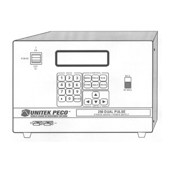
CHAPTER 1 SYSTEM DESCRIPTION Applications The 250DP (figure 1-1) is a versatile, 250 watt-second stored energy, capacitor discharge, dual pulse power supply which can effectively solve most precision, small parts, resistance welding problems. Its exclusive, context sensitive, user help screens quickly guide you through even the most complex program. Figure 1-1. -
Page 14: Features
CHAPTER 1: SYSTEM DESCRIPTION You can program up to 128 weld schedules and save them in battery backup memory. A built-in schedule protection feature protects weld schedules from unauthorized or inadvertent changes. Schedule 0 serves as a scratch-pad which anyone can use to perform occasional jobs without jeopardizing the integrity of the production line. - Page 15 CHAPTER 1: SYSTEM DESCRIPTION You can specify the polarity of the output pulse for each weld schedule. CAUTION: If weld schedules are chained together, do NOT change polarity. All schedules in the chain must have the same polarity or the relay contacts may be damaged. An optional built-in Weld Sentry monitors the process, signals reject alarms, calculates statistical and SPC data, displays graphs and charts and transmits, via an RS-232 interface, to a printer or PC.
- Page 16 CHAPTER 1: SYSTEM DESCRIPTION The foot switch weld abort safety feature causes the 250DP to abort the welding process if you release the foot switch, on an air actuated system, before the end of the welding sequence. The line failure turndown safety feature discharges the capacitor bank when input power is interrupted. The 250DP is protected from radio frequency interference and electromagnetic interference, resulting in reliable operation even in high electrical noise environments.
-
Page 17: Chapter 2: Installation
CHAPTER 2 INSTALLATION Location Install the 250DP in a well-ventilated area that is free from dirt and moisture. Allow sufficient clearance around the sides and rear of the unit so that cooling air may flow properly. Position the 250DP as close as practical to the weld head. -
Page 18: Cable Routing Examples
CHAPTER 2: INSTALLATION Tape cables together to minimize the inductive losses. A separation of weld cables surrounding an area of one square foot could result in losses of up to 65% (figure 2-1). DON’T Cables taped together and routed away from steel structure and Weld electromagnetic field Head... -
Page 19: Rear Panel Components
CHAPTER 2: INSTALLATION Rear Panel Components The input and output connections located on the rear panel of the 250DP (figure 2-3) are listed below. CB 1 CB 2 CO NT RO L SIG NA L ;S ACC ESSO R Y PO R T O P TIC AL FI RING SW IT CH ME CH ANICAL AIR VA LV E D RIVER 1 F OO T SW IT CH... -
Page 20: Firing Switch Connections
CHAPTER 2: INSTALLATION F FOOTSWITCH: This receptacle is used to connect either a 1-level or 2-level Unitek Peco footswitch. Footswitches are only used with air or electrically actuated weld heads. G MECHANICAL FIRING SWITCH: 4-foot cable is used to connect the 250DP to the force firing switch in all Unitek Peco weld heads and hand-pieces. -
Page 21: Air Actuated Weld Head Connections
CHAPTER 2: INSTALLATION Air Actuated Weld Head Connections Solenoid valve/regulator assemblies which are not mounted on the weld head should be located as close as possible to the weld head. Use the shortest air lines possible to obtain the fastest mechanical response. Connect the inlet port on the air valve (solenoid) to a properly filtered air supply (100 psig maximum). -
Page 22: Air Valve Driver
CHAPTER 2: INSTALLATION Figure 2-4. Typical Solenoid Air Valve Assembly with a Single Regulator Air Valve Driver Connect the solenoid air valve to the AIR VALVE DRIVER 1 receptacle located on the rear panel of the 250DP. Weld heads with 4-pin 24/115 VAC connectors can be plugged directly into the power supply. Weld Heads with standard 115 volt plugs (NEMA 5-15P) require an adapter, Unitek Peco Model VDAC, Valve Driver Adapter Cable. -
Page 23: Air Actuated Weld Heads Without Force Firing Switches
CHAPTER 2: INSTALLATION Non Unitek Peco Air Actuated Weld Heads Users of air actuated weld heads not manufactured by Unitek Peco should connect the air solenoid valve on the head or regulator valve assembly to either the appropriate 24 volt or 115 volt pins of the receptacle on the rear of the 250DP. -
Page 24: 2-Level Footswitch
CHAPTER 2: INSTALLATION 2-Level Footswitch When a 2-level footswitch is pressed to the first level, the weld head will close and apply force to the workpiece. At this point, if the operator does not press further (harder) and actuate the second level, the footswitch can be released so that the workpiece can be re-positioned. -
Page 25: Interconnection Diagram
CHAPTER 2: INSTALLATION Interconnection Diagram Refer to figure 2-5 for a wiring diagram of the 250DP as it is interconnected with external equipment. MODEL 250DP DUAL PULSE RESISTANCE WELDING POWER SUPPLY 990-280... -
Page 27: Chapter 3: Operating Controls And Screens
CHAPTER 3 OPERATING CONTROLS AND SCREENS Operating Controls Figure 3-1 illustrates the layout of the operating controls on the front panel of the 250DP. Figure 3-1. Front Panel Controls MODEL 250DP DUAL PULSE RESISTANCE WELDING POWER SUPPLY 990-280... - Page 28 CHAPTER 3: OPERATING CONTROLS AND SCREENS The controls on the front panel are identified as follows: NOTE: Instructions in the manual to “press [ ]” means that you are to press the key or button described inside the brackets. For example, “Press [PROG]” means that you should press the key labeled PROG on the front panel.
-
Page 29: Screen Formats
CHAPTER 3: OPERATING CONTROLS AND SCREENS DESCRIPTION [MENU] In either the run or program state, [MENU] will provide you with a menu which allows you to select or change options which are common to all schedules. [HELP] The 250DP contains a built-in operation manual. Press this key whenever you need HELP or additional information from the built-in manual. - Page 30 CHAPTER 3: OPERATING CONTROLS AND SCREENS Schedule number (0 - 127) Weld Sentry program lines – Program (A-E), Polarity of output welding pulses last weld results, measurement unit, upper/lower Energy of Weld Pulse 1 limits, Sentry status Energy of Weld Pulse 2 (dual pulse) Weld function: basic, repeat or roll-spot Type of weld head and foot switch Weld counter step count for next schedule...
-
Page 31: Screen Flow Chart
CHAPTER 3: OPERATING CONTROLS AND SCREENS Figure 3-2. Screen Flow Chart MODEL 250DP DUAL PULSE RESISTANCE WELDING POWER SUPPLY 990-280... -
Page 33: Chapter 4: Getting Started
CHAPTER 4 GETTING STARTED Powering Up 1 Set the front panel POWER Switch to ON. 2 To prevent the 250DP from firing until you are ready to weld, select [NO WELD]. 3 Press [ ] to change the weld schedule number. 4 Press [CHNG] to change the format of the RUN state screen. - Page 34 CHAPTER 4: GETTING STARTED 1 Refer to the appropriate weld head manual instructions on how to install the welding electrodes. 2 To adjust the pressure regulators and flow controls, refer to the following instructions or those which are printed on the side of the weld head. 3 To prevent the 250DP from firing until you are ready to weld, select [NO WELD].
-
Page 35: Typical Solenoid Air Valve System With A Single Regulator
CHAPTER 4: GETTING STARTED Figure 4-2. Typical Solenoid Air Valve System with a Single Regulator 5 Unlock the regulator(s) by pulling the red ring up. Set the air gauge(s) for 25 psig. Fully open both flow controls. 6 The operational sequence with an air head is as follows: The first level of a 2-Level foot switch actuates the weld head, moving the electrodes together. -
Page 36: Measuring Preset Firing Force Of The Weld Head With A Force Gauge
CHAPTER 4: GETTING STARTED 7 Adjust the upspeed flow control on the top of the cylinder so that the upper arm of the weld head moves at a reasonable rate but does not slam against the up-stop. This adjustment is made by pressing, then quickly releasing, the foot switch. -
Page 37: Results Of Excessive Air Pressure
CHAPTER 4: GETTING STARTED CAUTION: Resist the temptation to increase the downspeed by increasing the regulator setting since this increases the force applied to the workpiece by the electrodes (see figure 4-4). Illustration (a) in figure 4-4 shows the correct air pressure adjustment – the actual force equals the firing force setting. Illustration (b) shows the result of excessive air pressure –... - Page 38 CHAPTER 4: GETTING STARTED 15 If appropriate, modify the Weld Sentry program. To develop a Weld Sentry program, use the Weld Sentry basic setup option, which is accessed by pressing [MENU] and selecting WELD SENTRY followed by BASIC SETUP. 16 If you want to see a graphical representation of a weld schedule, select DISPLAY GRAPH OF LAST WELD from the Weld Sentry print utility menu.
-
Page 39: Chapter 5: Operating Instructions
CHAPTER 5 OPERATING INSTRUCTIONS Successful Welding This chapter is a guide to be used in establishing the parameters required to make a successful weld, then making and evaluating a weld. The development of an optimum weld schedule will aid in achieving a repeatable, reliable process. -
Page 40: Weld Head Parameters
CHAPTER 5: OPERATING INSTRUCTIONS HEAT TIME PROBLEM CAUSE PROBLEM CAUSE Parts Overheating Excessive Parts Overheating Excessive Weak Weld Weak Weld Insufficient Nugget Insufficient Nugget Metal Expulsion Metal Expulsion Warping Warping Discoloration Discoloration Electrode Damage Insufficient Electrode Damage Insufficient FORCE PROBLEM CAUSE Parts Overheating Excessive... -
Page 41: Recommended Electrode Materials
CHAPTER 5: OPERATING INSTRUCTIONS Table 5-1. Recommended Electrode Materials Electrode Electrode Electrode Electrode Material RWMA Material RWMA Material RWMA Material RWMA Type Type Type Type Alumel Evanohm Kulgrid Palladium Aluminum Gold Magnesium Rhenium Aluminum Gold Plated Manganin Silver Alloys Dumet Beryllium Gold Plated Molybdenum... -
Page 42: 250Dp Power Supply Parameters
CHAPTER 5: OPERATING INSTRUCTIONS 250DP Power Supply Parameters You can develop weld schedules using Schedule 0, then copy it to any other schedule number. Single Pulse Operation. Select pulse width and % energy as follows: Pulse Width: Short % Energy, Pulse 1: % Energy, Pulse 2: Dual Pulse Operation. -
Page 43: Weak Weld
CHAPTER 5: OPERATING INSTRUCTIONS Weak Weld If the parts pull apart easily, or there is little or no residual material pulled, the weld is weak. Increase the %ENERGY in increments of 1% to 2%. The actual weld strength is a user defined specification. Electrode Sticking Electrode sticking includes burning, sparking, and "blown welds."... -
Page 44: Polarity
CHAPTER 5: OPERATING INSTRUCTIONS The higher the electrode force, the greater the energy (current and/or time) required to produce a given weld. Low force usually results in lower bond strength. Increased force requires higher energy but usually results in a stronger bond. Energy is proportional to time and the square of the welding current. Polarity Users of stored energy equipment have found that the direction of current flow can have a marked effect on the weld characteristics of some material combinations. -
Page 45: Weld Strength Profiles
CHAPTER 5: OPERATING INSTRUCTIONS Weld Strength Profiles Electrode Force A = 8 lbs Weld strength profiles are graphic presentations B = 10 lbs of the varying effects of %ENERGY and C = 12 lbs electrode force. To make a weld strength D = 14 lbs profile, start at an initial energy setting, make four or five welds, and perform pull tests for... -
Page 46: Electrode Maintenance
CHAPTER 5: OPERATING INSTRUCTIONS Electrode Maintenance Depending on use, periodic tip resurfacing is required to remove oxides and welding debris from electrodes. On the production line, you should use No.400-600 grit electrode polishing disks. For less critical applications, you can use a file to clean a badly damaged tip. After filing, however, use polishing disks to ensure that the electrode faces are smooth and parallel. -
Page 47: Chapter 6: Process Definitions And Weld Functions
CHAPTER 6 PROCESS DEFINITIONS AND WELD FUNCTIONS 250DP States The 250DP has seven states: RUN, NO WELD, PROGRAM, MENU, HELP, STANDBY and FIRE. The [MENU], [RUN], and [PROG] keys cause the 250DP to change to the state defined by that key. RUN State In this state, the 250DP is ready to make a weld. -
Page 48: Standby State
CHAPTER 6: PROCESS DEFINITIONS AND WELD FUNCTIONS (c) Run State showing Weld 1 Energy Level. (d) Run State with the Weld Sentry Air Head using Rollspot Weld Function. Installed and Sentry Status Displayed STANDBY State The 250DP is waiting for a mandatory event to occur such as: The force firing switch in an air head to close, or The schedule number information to be placed on the terminals of the CONTROL SIGNALS connector, or... -
Page 49: Menu State
CHAPTER 6: PROCESS DEFINITIONS AND WELD FUNCTIONS Use the cursor to move to the field you wish to change. After you have made the changes, press [SAVE] to exit to the RUN state and save the changes. MENU State In this state, the 250DP will display a menu which allows you to select options which are common to all weld schedules, to access the Weld Sentry option, and obtain general information. -
Page 50: Help State
CHAPTER 6: PROCESS DEFINITIONS AND WELD FUNCTIONS HELP State The 250DP offers you context sensitive help when running or programming. Press [HELP] whenever you have a question. Press [HELP] again to return to the original screen. For example, if you press [HELP] from the RUN state, information on the function of the 250DP keys will be displayed as illustrated below: Typical HELP screens. -
Page 51: Basic Function
CHAPTER 6: PROCESS DEFINITIONS AND WELD FUNCTIONS Basic Function This function makes a simple spot weld. It provides the solution for the majority of the resistance welding applications. It is designed for both air actuated weld heads and manually actuated weld heads. -
Page 52: Repeat Function
CHAPTER 6: PROCESS DEFINITIONS AND WELD FUNCTIONS When the 250DP is initiated, or After Pulse 1, or After Pulse 2, or During the cool or off periods, or When the 250DP is in the RUN state waiting for the welding sequence to start. The status of each relay, shown on Lines 6 and 7, is set in the PROGRAM state and is confirmed, in real time, in the RUN state. -
Page 53: Rollspot Function
CHAPTER 6: PROCESS DEFINITIONS AND WELD FUNCTIONS Rollspot Function While the force firing switch remains closed, the weld/cool sequence will be repeated. The cool time and the rotational speed of the wheel electrodes determines the distance between spots. Assuming a reasonable wheel speed, the cool period could be reduced so that the spots would overlap. -
Page 55: Chapter 7: Maintenance
CHAPTER 7 MAINTENANCE Modification and Calibration Unless you are a skilled technician, we suggest you telephone the Unitek Miyachi Repair Department at the telephone number shown in the Foreword of this manual for advice before attempting calibration and/or modification. WARNING: Contact with voltages present in this power supply may cause serious or fatal injuries. Cover Removal It will be necessary to remove the outside cover to perform calibration or modifications. -
Page 56: Line Voltage Changes
CHAPTER 7: MAINTENANCE Figure 7-1. Line Voltage and Capacitor Bank Jumpering 1. Display units should be set to % Energy not Watt-Seconds. 2. Set the front panel POWER switch to OFF. 3. Remove the cover. 4. Remove Jumper A connecting the center terminals. 5. - Page 57 CHAPTER 7: MAINTENANCE 2. Remove the cover. 3. Select the schematic of the primary circuit for the required voltage, figures 7-2 through 7-5. Check the connections and reconfigure the following components: Jumpers E3 and E4, located in the top center area of the control printed circuit board. Bead Pins BP1-BP14 and Terminals E2 and E3, located along the top edge of the control printed circuit board.
-
Page 58: Vac Line Voltage Configuration
CHAPTER 7: MAINTENANCE Figure 7-2. 100 VAC Line Voltage Configuration MODEL 250DP DUAL PULSE RESISTANCE WELDING POWER SUPPLY 990-280... -
Page 59: Vac Line Voltage Configuration
CHAPTER 7: MAINTENANCE Figure 7-3. 115 VAC Line Voltage Configuration MODEL 250DP DUAL PULSE RESISTANCE WELDING POWER SUPPLY 990-280... -
Page 60: Vac Line Voltage Configuration
CHAPTER 7: MAINTENANCE Figure 7-4. 208 VAC Line Voltage Configuration MODEL 250DP DUAL PULSE RESISTANCE WELDING POWER SUPPLY 990-280... -
Page 61: Vac Line Voltage Configuration
CHAPTER 7: MAINTENANCE Figure 7-5. 230 VAC Line Voltage Configuration MODEL 250DP DUAL PULSE RESISTANCE WELDING POWER SUPPLY 990-280... -
Page 62: Calibration
CHAPTER 7: MAINTENANCE Calibration The 250DP should not require any regular adjustments. Use the following procedure as a guideline to check the calibration. Take care not to make unnecessary adjustments; however, if any components or software are replaced, check the calibration. Do not hesitate to call the Unitek Miyachi Repair Department with any questions. -
Page 63: Power Supply Voltage Range Specifications
CHAPTER 7: MAINTENANCE Table 7-1. Power Supply Voltage Range Specifications Power Supply Test Point Acceptable Range (V) +15V C 21 (+) +14.25 to +15.75V -15v C 23 (-) -14.25 to -15.75V C 26 (+) +4.75 to +5.25V Commutation Supply CR 35 Cathode +101.5 to +106.5* +5V Reference U19, Pin 6... -
Page 64: Troubleshooting
CHAPTER 7: MAINTENANCE To adjust the trimpots, press [ENTER] to display the calibration screen listing the trimpot adjustments. Adjust the trimpots as instructed on the screen. NOTE: The current measured at TP5 must not drift more than ±1.5?A. µA. Replace the cover and top screws. Securely tighten all screws. Troubleshooting If the circuit breaker trips repeatedly, one of the following is probably the cause: Overload - Exceeding the duty cycle. -
Page 65: Repair Service
CHAPTER 7: MAINTENANCE Repair Service Telephone Service Call the Unitek Miyachi Repair Department at the telephone number shown in the Foreword of this manual. Before calling, please obtain the model number and serial number from the identification plate on the rear panel. Factory Service Repair Unitek Miyachi provides a repair service for both warranty and non-warranty repairs. -
Page 67: Appendix A: Technical Specifications
APPENDIX A TECHNICAL SPECIFICATIONS 250DP Power Supply 1.5 to 250 watt-second (joules) stored energy power supply which can operate in a single or dual pulse mode. Is capable of operating with air or manually actuated weld heads. Compatible with 1-level or 2-level footswitches. -
Page 68: Weld Fire Lockout
APPENDIX A: TECHNICAL SPECIFICATIONS Table A-1. Pulse Characteristics Pulse Transformer Capacitor Rise Pulse Pulse Height Connections Bank Time Width SHORT (Parallel) 1.6 ms 6.7 ms 6.7 V - 7.4 V MEDIUM 3000 μF 2.1 ms 7.8 ms 5.7 V - 6.4 V LONG (Series) 2.6 ms 10.7 ms... -
Page 69: Over-Voltage Lockout
APPENDIX A: TECHNICAL SPECIFICATIONS Over-Voltage Lockout Protects the capacitor bank from damage due to circuit malfunction or improper calibration. The circuit breaker opens, removing primary power, and the line failure turndown circuit automatically discharges the capacitor bank. The circuit is adjusted to operate when 440 ± 1 volts is placed across the capacitor bank. - Page 70 APPENDIX A: TECHNICAL SPECIFICATIONS Table A-2. Welding Speed 1500 μF Capacitor 3000 μF Capacitor BANK Rep Rate Hit Rate Rep Rate Hit Rate Percent Full Energy (welds/min) (welds/min) (welds/min) (welds/min) 100% Conditions: 25 C Ambient, Nominal Line Voltage, 60 Hz. In dual pulse operation, the repetition rate or hit rate for each individual pulse may be calculated as follows: = First Pulse Rep Rate (Hit Rate) = Second Pulse Rep Rate (Hit Rate)
- Page 71 APPENDIX A: TECHNICAL SPECIFICATIONS % ENERGY INTERMITTENT AND CONTINUOUS REP RATE WATT-SECONDS Figure A-1. Rep/Hit Rate with 1500 μF Capacitor Bank % ENERGY INTERMITTENT REP RATE CONTINUOUS REP RATE WATT-SECONDS Figure A-2. Rep/Hit Rate with 3000 μF Capacitor Bank MODEL 250DP DUAL PULSE RESISTANCE WELDING POWER SUPPLY 990-280...
-
Page 72: Weld Schedules
APPENDIX A: TECHNICAL SPECIFICATIONS Weld Schedules You can save (write) 127 different weld schedules in SRAM (Static Random Access Memory.) In this manual, SRAM is referred to as permanent memory. Weld schedules are numbered 1 through 127. Weld Schedule Definition A weld schedule is defined as the following information: Schedule number (0 - 127) g Energy of Pulse 1 and Pulse 2... -
Page 73: Schedule Number At Power-Up
APPENDIX A: TECHNICAL SPECIFICATIONS Schedule Number at Power-Up This option determines which schedule will be used when the 250DP is switched to ON. The option will be either Schedule Number 0 - 127 or the schedule which was selected just before the power was switched to OFF. -
Page 74: System Setup
APPENDIX A: TECHNICAL SPECIFICATIONS System Setup Default System Parameters are: Head Type = Auto g Power-Up Schedule = 0 b Footswitch = Auto h End Cycle Buzzer = Off Footswitch Weld Abort = On i Chain Schedule Feature = Off d Force Firing Switch = 2-Wire j Switch Debounce = 0.01 sec Display Units = % Energy... -
Page 75: Cool Time
APPENDIX A: TECHNICAL SPECIFICATIONS Cool Time Cool time is the time between welds. In the rollspot function, the electrodes are wheels. The cool time and the rotational speed of the wheels determine the distance between welds. An air head will not open until the footswitch is released. -
Page 76: Footswitch Weld Abort Feature
APPENDIX A: TECHNICAL SPECIFICATIONS Footswitch Weld Abort Feature The footswitch weld abort feature is controlled from the options menu. Footswitch Weld Abort On With FOOTSWITCH WELD ABORT ON selected, the welding sequence is initiated by the closure of the initiation switch, and continues to its conclusion as long as the initiation switch remains closed. If the initiation switch or the force firing switch open during the welding sequence, the sequence will terminate. -
Page 77: Switch Debounce Time
APPENDIX A: TECHNICAL SPECIFICATIONS Switch Debounce Time Single pole mechanical firing switch contacts 'bounce' when they close. The switch debounce time feature allows you to specify that the firing switch must remain closed for 0, 10, 20 or 30 milliseconds before the weld period can be initiated. -
Page 78: Initiation Switch
APPENDIX A: TECHNICAL SPECIFICATIONS Initiation Switch Manual Head Operation If the 250DP is connected to a manual head, the initiation switch is the force firing switch located in the weld head. Air Head Operation If the 250DP is connected to an air actuated head, the initiation switch is the footswitch. The first level of a 2-level footswitch instructs the 250DP to: Switch the valve driver to ON, which causes the upper electrode of the weld head to apply force, as determined by the air regulator connected to the top of the air cylinder on the weld head, to the... -
Page 79: Next Schedule
APPENDIX A: TECHNICAL SPECIFICATIONS Next Schedule NEXT SCHEDULE is the number of the weld schedule to be used when the step count reaches zero. Any schedule number from 001 to 127 can be used and any number of schedules can be chained together, with some exceptions as follows: Next Schedule = 0: Can only be used at the beginning of a chain. -
Page 80: Weld Counter
APPENDIX A: TECHNICAL SPECIFICATIONS Weld Counter A seven-digit weld counter automatically increments after each complete weld sequence. This counter can be reset back to 0 at any time unless the system security is in the protected state. The Weld Sentry option allows you to set upper and lower limits for each Weld Sentry program. To implement this feature, there are three additional counters which keep track of the number of welds: under the lower limit (999,999), over the upper limit (999,999), and within these limits (9,999,999). -
Page 81: Air Valve Driver 2
APPENDIX A: TECHNICAL SPECIFICATIONS Air Valve Driver 2 Rear of Unit The output of the AIR VALVE DRIVER 2 receptacle provides 24 VAC to power a second air actuated weld head. Jumpers E10 and E11, located near the lower right hand corner of the control board must be moved to the correct Jumpers Jumpers... -
Page 82: Emergency Stop
APPENDIX A: TECHNICAL SPECIFICATIONS The CONTROL SIGNALS connector ( figure A-5) is a Viking DMRST15RA05CG (Unitek Peco PN 250- 195). The mating connector, which included in the shipping kit, is a TRW Cinch Connector comprised of a DA-15P (Unitek Peco PN 250-199) male connector and a DE-51210-1 (Unitek Peco PN 250-200) plastic junction shell. -
Page 83: Charge (Process) Inhibit
APPENDIX A: TECHNICAL SPECIFICATIONS Charge (Process) Inhibit Shorting Pin 9 to Pin 11 will close the charge (process) inhibit line and prevent recharging of the capacitor bank. The charge inhibit line is used during remote schedule selection to prevent the capacitors from recharging to a higher energy schedule when loading a lower energy schedule. -
Page 84: Binary Schedule Selection Code
APPENDIX A: TECHNICAL SPECIFICATIONS Binary Schedule Selection Code To select a schedule, connect the pin(s) corresponding to the schedule number to Pin 11. The schedules listed below are selected using the pin indicated by the 1 marked under the pin number. To select any other schedule number, select the schedule numbers whose sum equals the desired schedule, then connect all of the corresponding pins. -
Page 85: Relay Outputs
APPENDIX A: TECHNICAL SPECIFICATIONS Relay Outputs Two output relays can be used to provide status (timing) signals to external devices. They can also provide an on (closed) state during a Run state or if there is an alarm. Relay 1 can also be used to control a second 24 VAC air actuated weld head. (Refer to Air Actuated Weld Head Connections for the appropriate hook-up connections and figure A-3 for appropriate jumper connections.) Relay 2 can provide a 5 to 50 VDC signal. -
Page 86: Accessory Port
APPENDIX A: TECHNICAL SPECIFICATIONS Accessory Port A 25-pin, sub-miniature D-type connector, located on the rear panel, is provided to control other devices contemplated for the future. Input/Output Cable Connectors and Fusing Input Line Power The 250DP may be connected to any 100, 115, 208, or 230 volt outlet that is capable of supplying the peak currents specified in table A-4. -
Page 87: Front Panel Switches
APPENDIX A: TECHNICAL SPECIFICATIONS Table A-4. Input Power Specifications Nominal Line Line Peak Input Circuit Circuit Line Voltage Voltage Frequency Current * Breaker Breaker (Volts RMS) Range (Hz) (Amps) Size Quantity (Volts (Amps) RMS) 87 - 113 50/60 100 - 130 50/60 180 - 235 50/60... -
Page 88: Physical Characteristics
APPENDIX A: TECHNICAL SPECIFICATIONS Physical Characteristics Figure A-7. 250DP Dimensions NOTE: Dimensions are inches/centimeters Weight is 99 Pounds/45 Kilograms MODEL 250DP DUAL PULSE RESISTANCE WELDING POWER SUPPLY A-22 990-280... -
Page 89: Index
Index -C- (continued) Accessory port ........A-20 Optical firing switch ....... 2-4 Air actuated weld head: Second air head....... 2-7 Adjustments ........4-1 Controls, front panel ......3-1 Connections ........2-5 CONTROL SIGNALS connector..A-15 Excessive air pressure results ..4-5 Cool time definition...... - Page 90 INDEX -F- (continued) Firing switch specifications ....A-10 Main menu information ......A-7 Footswitch connections......2-7 Main menu utilities ....... A-7 1-Level ........2-7 Maintenance: 2-Level ........2-8 Electrodes ........5-8 Footswitch specifications...... A-9 Power supply ........7-2 Footswitch weld abort......A-10 Manual Revision Record ......
- Page 91 INDEX -S- (continued) Rear panel components ......2-3 Step count ........A-12 Recommended electrode materials ..5-3 Sticking electrodes........ 5-5 Relay outputs ........2-8, A-19 Switch debounce time......A-11 Remote schedule selection....2-8, A-17 System: Removing the cover ......7-1 Default parameters......
- Page 92 INDEX -W- (continued) -W- (continued) Weld Sentry options and utilities..A-7 Welding considerations ......5-1 Weld strength profiles......5-7 Welding parameters ......5-1 Welding ........5-4 Welding schedule specifications ..A-6 Welding cable installation ....2-1 Welding speed specifications ....A-3 Wiring diagram, interconnection ..
Need help?
Do you have a question about the 250DPS and is the answer not in the manual?
Questions and answers