Toshiba 2000 User Manual
Integrated controller
Hide thumbs
Also See for 2000:
- User manual (214 pages) ,
- Quick reference manual (2 pages) ,
- User manual (49 pages)
Table of Contents
Advertisement
Quick Links
Download this manual
See also:
User Manual
Advertisement
Table of Contents

Related Manuals for Toshiba 2000


Summary of Contents for Toshiba 2000
- Page 1 6F8C1147 odel 2000 PROFIBUS Module User's Manual for S2T/S2E...
- Page 2 Important Information No patent liability is assumed by TOSHIBA Corporation with respect to use of information, illustrations, circuits, equipment or examples of application in this publication. TOSHIBA Corporation reserves the right to make changes and improvements to this publication and/or related products at any time without notice.
- Page 3 Safety Precautions This manual contains important information for the operator to operate this product safely and correctly and avoid bodily injury and property damage. Grasp the meanings of the following marks and their descriptions before reading this manual. Hazard Classifications Indicates a potentially hazardous situation which, if not avoided, could result in WARNING serious injury or death.
- Page 4 Markings used on the model 2000 and in this Manual Make sure warning markings are attached on the model 2000. If any of them are missing or the wording is illegible, contact Toshiba’s Service Department model 2000 PROFIBUS Module User’s Manual for S2T/S2E...
- Page 5 2. Precautions on Installation WARNING Mandatory Operation without grounding may cause accidental fire or shock. CAUTION Mandatory Mandatory Avoid the following locations when installing or Install this module at a place where storaging this module. maintenance and inspection are easy to do. •...
- Page 6 Be sure to turn off power before wiring. Otherwise, it can cause electric shock or malfunction of this module. CAUTION Mandatory It is assumed that the users have general knowledge of industrial electrical control systems. model 2000 PROFIBUS Module User’s Manual for S2T/S2E...
- Page 7 Mandatory This module is dedicated to the model 2000. When you attempt to perform program Mount them on the bases of the model 2000. change, forced output, RUN/HALT controls, Do not use them by themselves for other etc during operation, carefully check for purposes.
- Page 8 Otherwise it can cause failure, malfunction, installing. electrical shock or injury. Otherwise it can cause failure, malfunction or electrical shock. model 2000 PROFIBUS Module User’s Manual for S2T/S2E...
- Page 9 CAUTION Forbidden Mandatory Be careful not to hit or fall off this module by Place this modules removed from the unit on a accident. conductive mat or conductive bag (containing Excess shock can cause failure. a spare board, etc.) on an grounded desk. Otherwise, static electricity can damage components of the module.
- Page 10 Do not disassemble or modify this module and equipment. related equipment. Also, do not insert metal parts into them. Otherwise, it can cause malfunction or failure. They can cause fire or accidents . viii model 2000 PROFIBUS Module User’s Manual for S2T/S2E...
- Page 11 7. Safety Precautions on Disposal CAUTION Mandatory Mandatory Observe local regulations for disposal of the Following information is only for EU-member this module. states: The use of the symbol indicates that this product may not be treated as household waste. By ensuring this product is disposed of correctly, you will help prevent potential negative consequences for the environment...
- Page 12 Toshiba’s engineers. Immunity Toshiba is not liable for any loss caused by fire, earthquake, action by a third party, or other accidents, or the operator’s intentional or accidental misuse, incorrect use, or use under abnormal condition.
- Page 13 This manual presents the specifications of the data communication network "PROFIBUS" master module PF611 and slave module PF612 for the Integrated Controller V Series model 2000, and describes its operating procedures. Be sure to read this manual in order to use the module correctly.
- Page 14 (5) Where humidity is high or where there is condensation. 3. If the device internal or external temperature becomes abnormally high or if there is a malfunction, stop operation, turn off the power and contact the nearest Toshiba service station.
-
Page 15: Table Of Contents
CONTENTS ăăăăăăăăăăăăăăăăăăăăăăăăă Safety Precautions ăăăăăăăăăăăăăăăăăăăăăăăăăăăăăăăăăă Preface Chapter 1 Module Overview ăăăăăăăăăăăăăăăăă1 ăăăăăăăăăăăăăăăăăăăăăăăăăăăăăăăăăăăăăăăăăă 1.1 General Chapter 2 Configuration ăăăăăăăăăăăăăăăăăăăă3 2.1 System Configuration Exampleăăăăăăăăăăăăăăăăăăăăăă ăăăăăăăăăăăăăăăăăăăăăăăăăăăă 2.2 PF611 Module External ăăăăăăăăăăăăăăăăăăăăăăăăăăăă 2.3 PF612 Module External ăăăăăăă 2.4 Name of PF611 Module Components and Parts ăăăăăăă... - Page 16 8.2 PF611 DP system Informationăăăăăăăăăăăăăăăăăăăăăă ăăăăăăăăăăăăăăăăăăăăăăăăăăă 8.3 PF612 RAS Information Chapter 9 Appendixăăăăăăăăăăăăăăăăăăăăăăă ăăăăăăăăăăăăăăăăăăăăăăăăăăăăăăăăăă 9.1 Error Inspection ăăăăăăăăăă 9.2 Installing modules and Transmission Cable ăăăăăăăăăăăăăăăăăăăăăăăăăăăăăăăăăăăăăă 9.3 Connectors ăăăăăăăăăăăăăă 9.4 Sample Application Programs (T-PDS) model 2000 PROFIBUS Module User’s Manual for S2T/S2E...
-
Page 17: Chapter 1 Module Overview Ăăăăăăăăăăăăăăăăă1
For model 2000 (master) GPF611**S For model 2000 (slave) GPF612**S Summary of PROFIBUS module. Connected device Integrated Controller V Series model 2000 S2T and S2E. Engineering Tool PROSEC T-Series engineering tool T-PDS. Number of transmission 122 (maximum) stations (32 in each segment, expandable with repeater (up to 3)) Transmission speed 9.6 Kbps to 12 Mbps. - Page 18 Chapter 1 Module Overview The following module is used as the PROFIBUS-DP transmission controller for this module. Master module (PF611): HMS AnyBus Profibus DP Master (ABM-PDP) Slave module (PF612): HMS AnyBus Profibus DP Slave (ABS-PDP) model 2000 PROFIBUS Module User’s Manual for S2T/S2E...
-
Page 19: Chapter 2 Configuration Ăăăăăăăăăăăăăăăăăăăă3
Chapter 2 Configuration 2.1 System Configuration Example model 2000 S2T/S2E PF611 Configurator (PC) Terminating Shielded twisted pair cable resistor Terminating Motor drive unit Motor drive unit resistor Slave equipment Figure 2-1 System configuration example (1) model 2000 S2T/S2E PF611 Configurator (PC) -
Page 20: Pf611 Module External
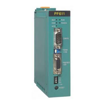
Chapter 2 Configuration 2.2 PF611 Module External Figure 2-3 PF611 appearance drawing model 2000 PROFIBUS Module User’s Manual for S2T/S2E... -
Page 21: Pf612 Module External
2.3 PF612 Module External 2.3 PF612 Module External Figure 2-4 PF612 appearance drawing 6F8C1147... -
Page 22: Name Of Pf611 Module Components And Parts
Resumes transmission using the transmission data prior to error. Resume 2 Resumes transmission using 0 as transmission data. Setting other than above will result in module failure. MD4 to 7 are all set to "OFF" at shipment. model 2000 PROFIBUS Module User’s Manual for S2T/S2E... - Page 23 2.4 Name of PF611 Module Components and Parts • Status LED Table 2-2 Status LED Transmission module normal Cyclic flash Firmware not stored. (1 Hz) RDY (green) Cyclic flash Hardware error or system error or in (4 Hz) downloading firmware configuration data Hardware failure Communicating Cyclic flash...
-
Page 24: Name Of Pf612 Module Components And Parts
Table 2-3 Mode 1 setup switch MODE1 I/O byte (word) count IN/OUT 2Byte(1Word) Set the same number of words for transmit and IN/OUT 4Byte(2Word) receive. IN/OUT 8Byte(4Word) IN/OUT 16Byte(8Word) IN/OUT 32Byte(16Word) IN/OUT 64Byte(32Word) IN/OUT 128Byte(64Word) IN/OUT 208Byte(104Word) model 2000 PROFIBUS Module User’s Manual for S2T/S2E... - Page 25 2.5 Name of PF612 Module Components and Parts MODE1 Input byte (word) count INPUT 2Byte(1Word) Set only transmit word count. INPUT 4Byte(2Word) INPUT 8Byte(4Word) INPUT 16Byte(8Word) INPUT 32Byte(16Word) INPUT 64Byte(32Word) INPUT 128Byte(64Word) INPUT 244Byte(122Word) MODE1 Output byte (word) count OUTPUT 2Byte(1Word) only receive...
- Page 26 The above figure is set to node address "00". (Actual setting should be between 1 and 99.) Align the notch side of the knob with the desired value. Figure 2-7 Node address setting model 2000 PROFIBUS Module User’s Manual for S2T/S2E...
- Page 27 2.5 Name of PF612 Module Components and Parts • Status LED Table 2-6 Status LED Communicating (green) Other than communicating Non-communicating (red) Other than non-communicating DIAG Cyclic flash Setup (configuration information) error (red) (1 Hz) Cyclic flash Setup (user parameter) error (2 Hz) Cyclic flash PROFIBUS ASIC initialization error...
-
Page 28: Configurator
RS232C connector of the PC with the CONFIG connector (9 pin male) of the PF611. Cable : Cross cable with 9-pin male connectors at both ends (Cross-cable for IBM-AT compatible PC) Transmission station 9-pin D -SUB Cable Figure 2-8 Configurator connection model 2000 PROFIBUS Module User’s Manual for S2T/S2E... -
Page 29: Chapter 3 Specifications
Chapter 3 Specifications 3.1 System Specification Table 3-1 System specification Item Description Transmission path configuration Number of transmission 122 (maximum) stations (32 in each segment, expandable with repeater (up to 3)) Transmission cable RS-485 Shielded twisted pair cable Transmission speed 9.6 K to 12 Mbps Transmission code Manchester... -
Page 30: Pf611/Pf612 Module Specification
45°C. External dimensions G2 I/O, occupies 1 slot EN50170 (DPV0) Conforming standard Profibus Class 1 Master Profibus-DP Slave • Module status RAS function • Healthy counter • PROFIBUS-DP status model 2000 PROFIBUS Module User’s Manual for S2T/S2E... -
Page 31: Chapter 4 Operation And Function
Chapter 4 Operation and Function 4.1 Cyclic Transmission The PF611 master cyclically reads input information from the slaves and cyclically writes output information to the slaves. The I/O area of the PF611 to the slaves are shown in the following table. Communication with slaves is performed by reading or writing to the specific address from the controller. -
Page 32: Operation And Function
Slave (PF612) Controller 100h 200h Input Input Area Output Output Area Area Area 200h 100h Output Output Input Input Area Area Area Area PROFIBUS-DP Figure 4-2 Cyclic transmission (PF611 and PF612 combination) model 2000 PROFIBUS Module User’s Manual for S2T/S2E... -
Page 33: Cyclic Transmission Time
4.2 Cyclic Transmission Time 4.2 Cyclic Transmission Time The cyclic transmission time depends on the transmission speed, number of slaves, and the number of transmitted words. The time required to read from the PF611 output area, transmit to slave, receive from slave, and write to PF611 input area is shown in the following table. - Page 34 PF612...ONL, ACC on, OFL, DIAG off See section 2.4, 2.5 Check the transmission data with each controller. • Check that expected data is transmitted on the master and slave side. Figure 4-4 Startup procedure example model 2000 PROFIBUS Module User’s Manual for S2T/S2E...
-
Page 35: Application Program (Start Procedure)
4.4 Applicaton program (start procedure) 4.4 Application Program (Start Procedure) It explains the PF611/PF612 start procedure by the application program. These requests are done by a special command for PF611/PF612. Please refer to Chapter 8 for details. Start procedure start When the power supply is turned Reading PF611/PF612 on, PF611/PF612 executes the... -
Page 36: Access For Pf611/Pf612 Controller Interface
Rw105: Number of words written in output area. 16 words are specified. D0080: It is a storage register of the written data. The writing data of 16 words is stored from "D0080" R0002: It is a start condition of this WRITE instruction. model 2000 PROFIBUS Module User’s Manual for S2T/S2E... - Page 37 Chapter 5 Transmission Parameter Setup When using this module, you must set the transmission parameters using the PROFIBUS configurator, in addition to the controller setup and registration. Use the following PROFIBUS configurator: Name: PROFIBUS SYSTEM CONFIGURATOR HMS SYCON Manufacturer: HMS INDUSTRIAL NETWORKS AB Supported OS: Windows95, Windows98, WindowsNT4.0 with Service Pack3 or higher, Windows2000 The basic setup procedure is described below.
-
Page 38: Chapter 5 Transmission Parameter Setup
Chapter 5 Transmission Parameter Setup model 2000 PROFIBUS Module User’s Manual for S2T/S2E... -
Page 39: Chapter 6 Operation Mode
Chapter 6 Operation Mode This chapter describes the PF611/PF612 operation mode and mode transition. 6.1 Operation mode Table 6-1 Operation mode Operation mode Explanation Initialize mode (a) Initializing hardware and software of PF611/PF612. When the power supply is turned on, it becomes this mode. When the reset request is issued from S2T/S2E, it becomes this mode. - Page 40 Standby mode Start request Initialization Reset request error detection S2T/S2E Transmission beginning is HALT waiting mode or ERROR Error detection Transmission beginning Down mode Online mode Error detection Figure 6-1 Operation mode transition model 2000 PROFIBUS Module User’s Manual for S2T/S2E...
-
Page 41: Chapter 7 Module Control
Chapter 7 Module Control This chapter explains the interface memory area of PF611/PF612 seen from S2T/S2E application program. PF611/PF612 allocates the sending and receiving data of the cyclic transmission to this memory area. Also, the request/response text area between S2T/S2E and PF611/PF612 is allocated on this memory area. - Page 42 Do not use 200h-279h Read data Input area from PF612 (122 words) 27Ah-17FFh Unused Do not use The address is the offset address (word address) from the beginning of the PF612 interface memory. model 2000 PROFIBUS Module User’s Manual for S2T/S2E...
-
Page 43: Module Control Information
7.2 Module Control Information 7.2 Module Control Information The information to control the PF611 or PF612 module is shown below. Table 7-3 Module control information (PF611) Address 0040h PF module control enable flag (1W) 0041h PF module control code (1W) Table 7-4 Module control information (PF612) Address 0040h... -
Page 44: Reset Pf Module
If resume transmission (resume transmission with 0 data or data prior to error occurrence) is selected for PF module operation setting when there is a controller error, activate PF module request is ignored and transmission is started when controller error is resolved. model 2000 PROFIBUS Module User’s Manual for S2T/S2E... -
Page 45: Pf612 Transmission Word Count Setup
7.5 PF612 Transmission Word Count Setup 7.5 PF612 Transmission Word Count Setup This procedure is used to set the PF612 module transmission word count. It is valid only when setup from the controller is selected with the MODE2 setup switch (MD7, MD6=ON, ON). - Page 46 Chapter 7 Module Control model 2000 PROFIBUS Module User’s Manual for S2T/S2E...
-
Page 47: Chapter 8 Ras Information
Chapter 8 RAS Information 8.1 PF611 RAS Information PF611 RAS information is referenced with READ instruction. Table 8-1 PF611 RAS Information Address 0000h PF module status (1W) 0001h Healthy counter (1W) 0002h Device error (1W) 0010h PROFIBUS-DP status (32W) The address is the offset address (word address) from the beginning of the PF611 interface memory. - Page 48 Error causing remote address 0012h Bus error counter 0013h Timeout counter 0018h Slave setting status (bit for each slave) 0020h Slave operating status (bit for each slave) 0028h Slave diagnostic (bit for each slave) model 2000 PROFIBUS Module User’s Manual for S2T/S2E...
- Page 49 8.1 PF611 RAS information (a) Global error bit Indicates the PF module internal transmission control error status. Table 8-6 Global error bit Reserved(0) No data Auto clear Control → No data 1: 1 or more remote node is not exchanging data or is in error 0: Operating normally →...
- Page 50 Setup data read error Master Download setup information once more System error Master Contact Toshiba Others Unprescribed error Contact Toshiba (e) Bus error counter Table 8-10 Bus error counter Bus_Error_count Severe bus error counter model 2000 PROFIBUS Module User’s Manual for S2T/S2E...
- Page 51 8.1 PF611 RAS information (f) Timeout counter Table 8-11 Timeout counter Time_out_count PROFIBUS telegram exclusion count One reason for incrementing the counter might be bus cable short. (g) Slave setup state Table 8-12 Slave setup states 0018h 001Fh The numbers in the above table are node numbers. →...
-
Page 52: Pf611 Dp System Information
56 30 31 2E 30 30 30 20 04.06.97 30 34 2E 30 36 2E 39 37 (3) Master recognition Table 8-18 Master recognition Master recognition → Master module → Non-zero Slave module model 2000 PROFIBUS Module User’s Manual for S2T/S2E... - Page 53 8.2 PF611 DP system information (4) Data exchange mode Table 8-19 Data exchange mode Data Exchange Mode → Bus synchronous, device controlled → Bus asynchronous, device controlled → Standard, uncontrolled → Bus asynchronous, host controlled → Bus synchronous, host controlled Set to 5xh for PF611 module.
-
Page 54: Pf612 Ras Information
Indicates the normal operating status of the PF module. Table 8-26 Healthy counter 0001h Healthy Counter Indicates that the PF module is operating normally. A 16-bit counter that is updated every 100 ms. Returns to 0 after FFFFh. model 2000 PROFIBUS Module User’s Manual for S2T/S2E... -
Page 55: Error Inspection
No error detected ACC(green) Controller accessing Controller not accessing The acyclic flashing pattern is as follows. If the error is not resolved after repeatedly downloading configuration parameters from the configurator, please contact Toshiba. Start 1 Start 2 LED-on LED-off 6F8C1147... - Page 56 Controller accessing (green) Controller not accessing (3) Configurator diagnostic information The following diagnostic information can be checked using HMS SYCON. Refer to the configurator manual for more details. Figure 9-1 Configurator diagnostic information model 2000 PROFIBUS Module User’s Manual for S2T/S2E...
- Page 57 9.1 Error Inspection (4) Periodic check Please execute the following check by units of 1 month or several months. Table 9-2 Periodic check item Check item Method Judgment condition Processing in abnormal circumstances State of wiring Watching Is the fixation of the cable The cable is fixed by of cable loose?
-
Page 58: Installing Modules And Transmission Cable
When routing transmission cable were noise condition is poor, device error may occur due to noise. Installing the following ferrite core to the connector may improve the situation in this case. Product no.: E04SR200935A Manufacturer: Seiwa Electric Mfg. Co., Ltd. model 2000 PROFIBUS Module User’s Manual for S2T/S2E... -
Page 59: Connectors
9.3 Connectors 9.3 Connectors (1) Configurator connector (only PF611) Table 9-6 Configurator connector Signal name Description INPUT Receive data OUTPUT Transmit data OUTPUT Data terminal ready Ref. Ground OUTPUT Request to send INPUT Clear to send Case Protective ground (2) PROFIBUS-DP connector Table 9-7 PROFIBUS-DP connector Signal name Description... -
Page 60: Sample Application Programs (T-Pds)
| /* compare send data and receive data */ 12|[W0000 MOV YW000][D1300 MOV YW001]------------------------------------- | | /* compare error counter (W0000) copy to YW001 */ 13|[END ]-------------------------------------------------------------------------------------------- | Figure 9-3 Sample program of PF611 model 2000 PROFIBUS Module User’s Manual for S2T/S2E... - Page 61 9.3 Connectors (2) Sample program of PF612 In this sample program, PF612 is mounted on basic unit and slot 7 of S2T/S2E. Sample program issues the start request to PF612, reads from “Read data” area, and writes that data in “Write data” area. This program is registered in S2T/S2E.
- Page 62 Chapter 9 Appendix model 2000 PROFIBUS Module User’s Manual for S2T/S2E...
- Page 63 Integrated Controller series model 2000 PROFIBUS Module User’s Manual for S2T/S2E 1st edition 24 March, 2006 1147.1.0603 INDUSTRIAL AND POWER SYSTEMS & SERVICES COMPANY Electrical Apparatus & Measurement Division Overseas Sales & Marketing Department - Group 3 TEL.: +81-3-3457-4894 1-1, Shibaura 1-chome, Minato-ku, Tokyo 105-8001, Japan Microelectronics &...
- Page 66 6F8C1147 ROFIBUS Module User's Manual for S2T/S2E 1147.1.0603...