Yamaha CD-C600 Service Manual
Hide thumbs
Also See for CD-C600:
- Owner's manual (140 pages) ,
- Communications manual (4 pages) ,
- Owner's manual (23 pages)
Table of Contents
Advertisement
This manual has been provided for the use of authorized YAMAHA Retailers and their service personnel.
It has been assumed that basic service procedures inherent to the industry, and more specifi cally YAMAHA Products, are already known
and understood by the users, and have therefore not been restated.
WARNING:
IMPORTANT:
The data provided is believed to be accurate and applicable to the unit(s) indicated on the cover. The research, engineering, and service
departments of YAMAHA are continually striving to improve YAMAHA products. Modifications are, therefore, inevitable and
specifi cations are subject to change without notice or obligation to retrofi t. Should any discrepancy appear to exist, please contact the
distributor's Service Division.
WARNING:
IMPORTANT:
■ CONTENTS
TO SERVICE PERSONNEL ........................................2-3
FRONT PANEL ...............................................................5
REAR PANELS ...........................................................5-6
REMOTE CONTROL PANEL ..........................................7
SPECIFICATIONS ...........................................................8
INTERNAL VIEW ............................................................9
DISASSEMBLY PROCEDURES ............................. 10-14
STANDARD OPERATION CHART ......................... 15-16
TEST MODE .................................................................. 17
1 0 1 1 4 5
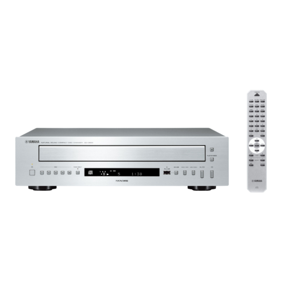
COMPACT DISC PLAYER
CD-C600
SERVICE MANUAL
IMPORTANT NOTICE
Failure to follow appropriate service and safety procedures when servicing this product may result in personal injury,
destruction of expensive components, and failure of the product to perform as specifi ed. For these reasons, we advise
all YAMAHA product owners that any service required should be performed by an authorized YAMAHA Retailer or
the appointed service representative.
The presentation or sale of this manual to any individual or fi rm does not constitute authorization, certifi cation or
recognition of any applicable technical capabilities, or establish a principle-agent relationship of any form.
Static discharges can destroy expensive components. Discharge any static electricity your body may have
accumulated by grounding yourself to the ground buss in the unit (heavy gauge black wires connect to this buss).
Turn the unit OFF during disassembly and part replacement. Recheck all work before you apply power to the unit.
FACTORY MODE .......................................................... 18
UPDATING FIRMWARE .......................................... 19-23
DISPLAY DATA .............................................................24
IC DATA ...................................................................25-33
PIN CONNECTION DIAGRAMS .............................34-35
BLOCK DIAGRAM ........................................................37
PRINTED CIRCUIT BOARDS .................................38-46
SCHEMATIC DIAGRAMS .......................................47-52
REPLACEMENT PARTS LIST ................................53-61
REMOTE CONTROL .....................................................62
Copyright © 2009
This manual is copyrighted by YAMAHA and may not be copied or
redistributed either in print or electronically without permission.
All rights reserved.
P.O.Box 1, Hamamatsu, Japan
'09.09
Advertisement
Table of Contents

Related Manuals for Yamaha CD-C600


Summary of Contents for Yamaha CD-C600
-
Page 1: Table Of Contents
This manual has been provided for the use of authorized YAMAHA Retailers and their service personnel. It has been assumed that basic service procedures inherent to the industry, and more specifi cally YAMAHA Products, are already known and understood by the users, and have therefore not been restated. -
Page 2: To Service Personnel
CD-C600 ■ TO SERVICE PERSONNEL AC LEAKAGE 1. Critical Components Information WALL EQUIPMENT TESTER OR OUTLET UNDER TEST EQUIVALENT Components having special characteristics are marked must be replaced with parts having specifications equal to those originally installed. 2. Leakage Current Measurement (For 120V Models Only) - Page 3 CD-C600 Laser Emitting conditions: 1) When the Top Cover is removed, and the STANDBY/ON SW is turned to the “ON” position, the laser component will emit a beam for several seconds to detect if a disc is present. During this time (5-10 sec.) the laser may radiate through the lens of the laser pick-up unit.
-
Page 4: Prevention Of Electrostatic Discharge
CD-C600 ■ PREVENTION OF ELECTROSTATIC DISCHARGE Some semiconductor (solid state) devices can be damaged easily by static electricity. Such components commonly are called Electrostatically Sensitive (ES) Devices. Examples of typical ES devices are integrated circuits and some field-effect transistors and semiconductor “chip” components. The following techniques should be used to help reduce the incidence of component damage caused by electrostatic discharge (ESD). -
Page 5: Front Panel
CD-C600 ■ FRONT PANEL U, C, R, A, G, L models ■ REAR PANELS U, C models R, L models... - Page 6 CD-C600 A model G model...
-
Page 7: Remote Control Panel
CD-C600 ■ REMOTE CONTROL PANEL CDC9... -
Page 8: Specifications
CD-C600 ■ SPECIFICATIONS ■ Audio Section Output Level (1 kHz, 0 dB) “iPod” is a trademark of Apple Inc., registered in U.S. and other countries...................2.0 ±0.3 V “Made for iPod” means that an electronic accessory has been designed Signal to Noise Ratio to connect specifically to iPod and has been certified by the developer to ................. -
Page 9: Internal View
CD-C600 ■ INTERNAL VIEW OPERATION (13) P.C.B. (R, L models) OPERATION (10) P.C.B. CM-230B UNIT CLAMP ASS’Y OPERATION (6) P.C.B. MAIN P.C.B. OPERATION (9) P.C.B. OPERATION (14) P.C.B. TRAY ASS’Y OPERATION (5) P.C.B. OPERATION (8) P.C.B. OPERATION (7) P.C.B. OPERATION (11) P.C.B. -
Page 10: Disassembly Procedures
CD-C600 ■ DISASSEMBLY PROCEDURES (Remove parts in the order as numbered.) 1. Removal of Top Cover Remove 4 screws ( ① ) and 3 screws ( ② ). (Fig. 1) b. Lift the top cover at the rear and move it rearward slantingly. - Page 11 CD-C600 • Precaution for installation of the Disc Tray Ass’y. CM-230B unit can not be removed without removing the Front Panel Unit. On disc tray ass’y setting. Check the direction of marking “ ” on gear according ▲ 5-A. Removal of Front Panel Unit to this drawing.
- Page 12 CD-C600 5-B. Removal of CM-230B Unit 6. Removal of PU Mechanism Unit Remove 2 push rivets and remove the barrier main. Remove 2 screws ( ⑩ ) and then remove the PU unit (Fig. 8) ass’y. (Fig. 10) b. Remove 2 push rivets and remove the barrier cable.
- Page 13 CD-C600 • Operation Check Procedure Disassembly 1) Remove the top cover. 2) Remove the clamp ass’y. 3) Unlock and remove the stabilizer from the holder. Turn the plate clockwise by 30° while holding the stabilizer, and the plate will come off. Remove the stabilizer from the holder.
- Page 14 CD-C600 g. Spread a cloth over the chassis. (Fig. 2) Put the MAIN, OPERATION (9) and (11) P.C.B.s on end. (Fig. 2) Ground point (PJ601) Remove 2 screws ( ⑤ ) and 3 screws ( ⑥ ). (Fig. 3) Remove the front panel unit from the chassis.
-
Page 15: Standard Operation Chart
CD-C600 ■ STANDARD OPERATION CHART Press the "OPEN/CLOSE" key. "OPEN" is displayed. Forced feed return operation. TRV signal is output until detection of FEED LIMIT switch. Proceeds to next step after detection of CLAMP switch. (SW501) Clamp down operation. Disc table reset. - Page 16 CD-C600 Focus gain adjustment. Tracking gain adjustment. *TOC READ * ~ Data fetch cycle ~ Track No. "1" is searched. : MUTE OFF = "L" → "H", "0:00" is displayed. After searching the beginning, Mute is cancelled. (IC305, pin 7) ~ PLAY ~ Set to search by means of "...
-
Page 17: Test Mode
CD-C600 ■ TEST MODE ● Starting Test Mode When starting the test mode, check the FL display and indicators for display/indication condition. 1. While pressing the “DISC 3”, “PURE DIRECT” and “ ” (Stop) keys of this unit as shown in the figure below, press the “POWER ON/OFF”... -
Page 18: Factory Mode
CD-C600 ■ FACTORY MODE ● Starting Factory Mode While pressing the “PURE DIRECT” and “ / ” (Play/Pause) keys of this unit as shown in the figure below, press the “POWER ON/OFF” switch to turn on the power. The Factory Mode is activated. -
Page 19: Updating Firmware
CD-C600 ■ UPDATING FIRMWARE After replacing the following parts with the replacement parts, update the latest firmware according to the following procedure. MAIN P.C.B. Microprocessor (IC305) of MAIN P.C.B. ● Required tools ● Connection • Program down loader program Turn off the power of this unit and disconnect the ............ - Page 20 CD-C600 3. Short circuit between both terminals of CB311 of the MAIN P.C.B.. (Fig. 2) Note) Be sure to return the shorted terminals to their original condition after updating firmware. CB311 CB311 (2P) MAIN P.C.B. Short Fig. 2 4. Connect the RS-232C terminal located on the rear panel of this unit to the serial port (RS232C) of the PC with RS232C cross cable as shown below.
- Page 21 CD-C600 ● Operation procedure 1. Connect the power cable of this unit to the AC outlet. 2. Press the “POWER ON/OFF” switch of this unit to turn on the power. 3. Start up FlashSta.exe. The screen appears as shown below. (Fig. 4) 4.
- Page 22 CD-C600 6. Click [Setting], and set the baud rate. (Fig. 6) Select 115200 bps for the baud rate and 40 ms for the program intervals. Reduce the baud rate if a transmission error occurs frequently. Fig. 6 7. Click [E.P.R.], then the “Erase” screen appears. (Fig. 7) 8.
-
Page 23: Updating Firmware
CD-C600 9. When writing of the firmware is completed, the screen appears as shown below. (Fig. 8) Click [OK]. (Fig. 8) 10. Click [Exit] to end FlashSta.exe. (Fig. 8) Fig. 8 11. Check that the firmware version is the same as written one by using the factory mode. -
Page 24: Display Data
CD-C600 ■ DISPLAY DATA ● V701: 14-ST-68GINK (OPERATION P.C.B.) ● PIN CONNECTION Pin No. Connection VFL VDDH VDD OSC RESET Pin No. Connection Pin No. Connection Q14G Q13G Note: 1) F1, F2 ..Filament 2) NP ..No pin 3) NX ..No extended pin 4) GND ..GND pin 5) VFL ..VFD driving voltage sink pin 6) VDD .. -
Page 25: Ic Data
CD-C600 ■ IC DATA IC2: LC786922E-01UY-E (MAIN P.C.B.) CMOS LSI compact disc player IC CLOCK GENERATOR EFMIN LRSY PCN Output Control RFOUT DATACK Audio Output DATA 8FS DIGITAL FILTER/ SLICE Control 1 bit DAC LEVEL PHLPF TEST CONTROL Stream Control/Audio Input... - Page 26 CD-C600 Function State During a Reset Detail of Function Name 1 EFMlN Input RF signal input 2 RFOUT Undefined RF signal output 3 LPF Undefined RF signal DC level detection low-pass filter capacitor connection 4 PHLPF Undefined Defect detection low-pass filter capacitor connection...
- Page 27 CD-C600 Function State During a Reset Detail of Function Name 69 DOUT Monitor pin / Digital audio data output (EIAJ format) 70 CONT4 Input (Low) General purpose input/output 4 (Initial : Input, internal pull-down resistor ON) 71 XVSS — —...
- Page 28 CD-C600 IC7: LC87F1HC8A (MAIN P.C.B.) CMOS LSI Interrupt control Standby control FROM USB PLL Clock generator X’tal SIO0 Bus interface Port 0 SIO1 B register Port 1 SIO4 C register SIO9 Port 2 Timer 0 Port 3 Timer 1 Port 7...
- Page 29 CD-C600 Pin No. Function Name Detail of Function Option 5, 20, 40 VSS1, VSS2, VSS3 – - power supply 8, 19 VDD1, VDD2 – + power supply VDD3 – USB reference voltage 21, 22, 23, 24, 25, 26, 27, 28 I/O •...
- Page 30 CD-C600 Pin No. Function Name Detail of Function Option 1, 46, 47, 48 Port 7 I/O • 4-bit I/O port P70 to P73 • I/O specifiable in 1-bit units • Pull-up resistors can be turned on and off in 1-bit units •...
- Page 31 CD-C600 IC305: R5F212CASNFP (MAIN P.C.B.) Single chip 16-bit microprocessor I/O ports Port P0 Port P1 Port P2 Port P3 Port P4 Port P5 Peripheral functions UART or System clock clock synchronous serial I/O generation circuit (8 bits x 3) Timers...
- Page 32 CD-C600 Pin No. Function Name Detail of Function EEP_WP Wright protection of EEPROM (IC304) EEP_SDA Serial data to EEPROM (IC304) DAC_/CS Chip select to audio DAC (IC302) DAC_SCL Serial clock to audio DAC (IC302) DAC_SDA Serial data output to audio DAC (IC302) OCD_MODE Input High -->...
- Page 33 CD-C600 Pin No. Function Name Detail of Function DSP_/RST Reset signal to CD-DSP REG_READY0 Input R_RDY signal from CD-DSP SUB_READY0 Input S_RDY signal from CD-DSP KEY_O/C Detect [O/C] KEY on front-panel KEY_USB Detect [CD/USB] KEY on front-panel KEY_PLAY Detect [PLAY/PAUSE] KEY on front-panel...
-
Page 34: Pin Connection Diagrams
CD-C600 ■ PIN CONNECTION DIAGRAMS • ICs BD5229G-TR BD9870FPS-E2 KIA7805API KIA79M05PI-U LA6510 OUTPUT INPUT LA6565-TE-L-E LC786922E-01UY-E LC87F1HC8A-F5AL1-E LE24C023M-TLM-E MAX3232CDWR MFI341S2161 NJM2068D-D PCM1780DBQR R1154N033B-TR-F R1172S331B-E2-F R5523N001A-TR-F R5F212CASNFP TA7291P TC74VHC126FT TC7SH08F TC7SH08FU... - Page 35 CD-C600 • Diodes 1SS355 2A02-05 XO MAZ8047GHL 4.9V Anode Anode Anode Anode Cathode Cathode Cathode Cathode MTZJ5.6B 5.6V RB050LA-40TR TP S1NB20 1A 200V MTZJ6.2B 6.2V RB501V-40 MTZJ7.5B 7.5V MTZJ8.2A 8.2V Anode Anode MTZJ30A 30V – Cathode Cathode • Transistors 2SA1037K...
- Page 36 CD-C600 MEMO...
-
Page 37: Block Diagram
CD-C600 ■ BLOCK DIAGRAM Analog Output Section Front Section OPERATION (9) → MAIN → OPERATION (1) – (4) DIGITAL OUT REMOTE CONTROL SCHEMATIC DIAGRAM SCHEMATIC DIAGRAM → OPTICAL RS-232C SCHEMATIC DIAGRAM ANALOG OUT U301 CB308 JK301 JK302 IC308 Q601-604 Photo... -
Page 38: Printed Circuit Boards
CD-C600 ■ PRINTED CIRCUIT BOARDS POINT A XL1 (Pin 73 of IC2) POINT B XL2 (Pin 6 of IC7) POINT C XL301 (Pin 10 of IC305) POINT D 1 / IC306 (2 pin), 2 / IC306 (1 pin) MAIN P.C.B. - Page 39 CD-C600 MAIN P.C.B. (Side B) IC304 • Semiconductor Location Ref no. Location D301 D303 D304 D305 D309 IC304 Q301 Q303 Q305 Q306...
- Page 40 CD-C600 OPERATION (1) P.C.B. (Side A) MAIN (CB304) • Semiconductor Location Ref no. Location D701 D702 D703 D752 CB702 OPERATION (11) (CB809) FLGND ACFL1 ACFL2 PURE DIRECT iPod/USB PLAY indicator indicator CHANGE PURE CD/USB DIRECT DISC DGND DGND DGND KEY2 LED_POWER OPERATION (2) P.C.B.
- Page 41 CD-C600 OPERATION (1) P.C.B. (Side B) • Semiconductor Location Ref no. Location IC701 Q701 Q702 Q703 Q704 Q705 Q706 OPERATION (2) P.C.B. OPERATION (3) P.C.B. OPERATION (4) P.C.B. (Side B) (Side B) (Side B)
- Page 42 CD-C600 OPERATION (5) P.C.B. OPERATION (6) P.C.B. OPERATION (7) P.C.B. OPERATION (9) P.C.B. (Side A) (Side A) (Side A) (Side A) ANALOG OUT IC501 CLAMP-UP/DOWN switch LOADING switch CB501 W501 CB502 IC601 IC602 LOADING MOTOR OPERATION (8) P.C.B. DISC CLAMP MOTOR...
- Page 43 CD-C600 OPERATION (5) P.C.B. OPERATION (6) P.C.B. OPERATION (7) P.C.B. OPERATION (9) P.C.B. (Side B) (Side B) (Side B) (Side B) OPERATION (8) P.C.B. (Side B) • Semiconductor Location Ref no. Location Q601 Q602 Q603 Q604...
- Page 44 CD-C600 Circuit No. U, C, A, G R, L J801, 803 OPERATION (10) P.C.B. (Side A) J802 U, C, A, G models R, L models GRAY W805B YELLOW ORANGE RED BROWN STBY W804B W803B W802B W801B S+33 MAIN (CB302) AC IN...
- Page 45 CD-C600 OPERATION (10) P.C.B. (Side B) R, L models OPERATION (12) P.C.B. (Side B) OPERATION (13) P.C.B. (Side B) R, L models • Semiconductor Location Ref no. Location D853 D854 D855 D856 OPERATION (14) P.C.B. (Side B) IC851 Q851...
- Page 46 CD-C600 OPERATION (11) P.C.B. OPERATION (11) P.C.B. (Side A) (Side B) OPERATION (10) (CB805) CB806 PGND OPERATION (8) (W502) • Semiconductor Location Ref no. Location D801 D802 D803 D804 IC802 IC801 D805 IC803 M2GND D806 D807 M1GND D808 DGND D809...
-
Page 47: Schematic Diagrams
CD-C600 SCHEMATIC DIAGRAMS MAIN 1/2 DIGITAL OUT ANALOG OUT CURRENT LIMIT SWITCH iPod/USB IN To PU mechanism unit Page 49 to OPERATION (4)_W703 CD CONTROLLER USB INTERFACE iPod/USB IN CD IN No replacement part available. IC1: LA6565-TE-L-E IC2: LC786922E-01UY-E IC7: LC87F1HC8A-F5AL1-E... - Page 48 CD-C600 MAIN 2/2 Page 49 Page 50 to OPERATION (1)_CB702 to OPERATION (8)_CB509 DIGITAL OPTICAL DC/DC CONVERTER SW BUFFER 11.9 IC301 IC309 IC309 IC309 IC309 IC309 232C DRIVER MICROPROCESSOR CB301 11.9 IC303 IC305 IC307 Page 52 to OPERATION (11)_CB807 -5.0 -4.4...
- Page 49 CD-C600 OPERATION 1/4 OPERATION (1) Page 52 to OPERATION (11)_CB809 -21.2 -21.2 -27.7 W701 -26.2 -26.2 -26.1 -26.1 iPod/USB CB705 IC701 Page 47 to MAIN_CB6 OPERATION (4) CB702 PURE DIRECT indicator Page 48 PLAY to MAIN_CB304 CHANGE W702A W702B iPod/USB...
- Page 50 CD-C600 OPERATION 2/4 OPERATION (5) OPERATION (8) W501 CB503 IC501 OPERATION (6) CB501 CB504 CLAMP-UP/DOWN SW TRAY OPEN/CLOSE DRIVER CB509 IC502 OPERATION (7) CB502 CB505 LOADING SW Page 48 to MAIN_CB306 CB506 LOADING MOTOR -13.5 W502 11.7 CB507 -13.5 Page 52...
- Page 51 CD-C600 OPERATION 3/4 OPERATION (9) 3 dB AMP L.P.F. IC601 IC601 -5.0 -4.5 -4.5 CB601 -5.0 Page 48 to MAIN_CB303 ANALOG OUT ANALOG OUT L -5.0 -4.5 -4.5 IC602 IC602 IC601, 602: NJM2068D-D Dual operational amplifier 2, 6 OUTPUT –INPUT –IN...
-
Page 52: Schematic Diagrams
CD-C600 OPERATION 4/4 OPERATION (10) CB851 Page 48 to MAIN_CB302 IC851: R1154N033B-TR-F Voltage regulator Thermal Shutdown 4 NC Vref Pin No. Symbol Description Short Current Output Pin for Voltage Regulator Protection Limit Ground Circuit Circuit Power Supply Pin AC8.1 B Version No Connection Chip Enable Pin (active at "H") -
Page 53: Replacement Parts List
CD-C600 ■ REPLACEMENT PARTS LIST • ELECTRICAL COMPONENT PARTS WARNING ● Components having special characteristics are marked and must be replaced with parts having specifications equal to those originally installed. ABBREVIATIONS IN THIS LIST ARE AS FOLLOWS: C.A.EL.CHP : CHIP ALUMI.ELECTROLYTIC CAP L.EMIT... - Page 54 CD-C600 P.C.B. MAIN Ref No. Part No. Description Markets Ref No. Part No. Description Markets WS180800 P.C.B. MAIN WJ881200 C.CE.CHP VB390200 CN.BS.PIN UF418100 C.EL.CHP 100uF 6.3V V2731000 CN.FMN C74-75 US135100 C.CE.CHP 0.1uF VB390100 CN.BS.PIN WJ881200 C.CE.CHP CB301 VK217300 CN WG251600 C.CE.CHP 4.7uF...
- Page 55 CD-C600 P.C.B. MAIN and P.C.B. OPERATION Ref No. Part No. Description Markets Ref No. Part No. Description Markets * IC1 YA727A00 IC LA6565 C609-610 UU238100 C.EL 100uF * IC2 YA748A00 IC.CD LC786922 (MASKROM) C611-612 WQ331800 C.EL 100uF XR680A00 IC TC7SH08FU(TE85L,JF C614-615 WJ608900 C.MYLAR...
- Page 56 CD-C600 P.C.B. OPERATION Ref No. Part No. Description Markets Ref No. Part No. Description Markets D805-810 VS997800 DIODE * T851 YA881A00 TRANS.PWR D811 VG443200 DIODE.ZENR MTZJ30A * T851 YA880A00 TRANS.PWR D812-813 VT332900 DIODE 1SS355 * TE801 WR903000 INLET.AC 2P HJC-036AP D814 VG438600 DIODE.ZENR MTZJ7.5B 7.5V...
- Page 57 CD-C600 Carbon Resistors Value 1/4W Type Part No. 1/6W Type Part No. Value 1/4W Type Part No. 1/6W Type Part No. 1.0 Ω HJ35 3100 HF85 3100 11 kΩ HF45 7110 HF45 7110 ✻ 1.8 Ω 3180 12 kΩ 7120...
- Page 58 CD-C600 • OVERALL ASS'Y 5-10 6-10 200-1 5-10 PU unit ass'y 5-10 CM-230B unit 3-30 3-19 3-30 11 (12) 11 (10) 3-30 11 (3) 3-13 3-30 11 (14) 3-30 3-16 11 (2) 11 (1) 3-30 3-11 3-30 3-14 3-18 3-30...
- Page 59 CD-C600 Ref No. Part No. Description Remarks Markets Ref No. Part No. Description Remarks Markets MF120350 FLEXIBLE FLAT CABLE 20P 350mm P=1.25 WE774100 BIND HEAD BONDING B-T. SCREW MFZN2B3 * 3-11 WR786000 FRONT PANEL V6509600 JACK SCREW SS6-A47511848 * 3-11...
- Page 60 CD-C600 • CM-230B UNIT 1-14 Ref No. Part No. Description Remarks Markets 1-29 MF114200 FLEXIBLE FLAT CABLE 14P 200mm P=1.25 1-19 V3175700 CONNECTOR ASS'Y 3P 220mm 1-21 V3175900 CONNECTOR ASS'Y 3P 220mm 1-18 1-10 VZ760500 CHASSIS B type 1-30 1-11...
- Page 61 CD-C600 • PU UNIT ASS'Y • GREASE APPLICATION DIAGRAM Apply the grease Molykote PG-663 (Part No. AAX01170) PG-663 PU MECHANISM UNIT 7-20 7-20 PG-663 7-13 7-11 7-11 7-12 7-12 PG-663 7-10 PG-663 Ref No. Part No. Description Remarks Markets * 7-1...
-
Page 62: Remote Control
CD-C600 ■ REMOTE CONTROL SCHEMATIC DIAGRAM PANEL KEY LAYOUT KEY CODE Customer Function Data Code Code STANDBY/ON CD/USB 3.3 ohms PURE DIRECT OPEN/CLOSE PROGRAM REPEAT IR-LED RANDOM DIMMER DISPLAY 47 uF/ 10 V TRKTC8050S 220 ohms 0.1 uF 15 pF... - Page 63 CD-C600 MEMO...
- Page 64 CD-C600...