Hytera TC-508 Service Manual
Hide thumbs
Also See for TC-508:
- Owner's manual (23 pages) ,
- Manual (23 pages) ,
- Owner's manual (19 pages)
Table of Contents
Advertisement
Contents
Revision Records ---------------------------------------------------------------------------------------------------------1
Copyright Information -------------------------------------------------------------------------------------------1
Disclaimer------------------------------------------------------------------------------------------------------------------------1
Introduction-----------------------------------------------------------------------------------------------------------------------1
Radio Overview-----------------------------------------------------------------------------------------------------------------3
Software Specifications------------------------------------------------------------------------------------------------------6
Circuit Description------------------------------------------------------------------------------------------------------11
CPU Pins-------------------------------------------------------------------------------------------------------19
Part List 1---------------------------------------------------------------------------------------------------------23
Adjustment Description --------------------------------------------------------------------------------49
Troubleshooting Flow Chart--------------------------------------------------------------------------------------------58
Disassembly and Assembly-----------------------------------------------------------------------------------------------61
Exploded View------------------------------------------------------------------------------------------------------64
Part List 2--------------------------------------------------------------------------------------------------------65
PCB View-------------------------------------------------------------------------------------------------------66
Level Diagram------------------------------------------------------------------------------------------------------68
Block Diagram------------------------------------------------------------------------------------------------------69
Schematic Diagram--------------------------------------------------------------------------------------------------------70
Specifications-----------------------------------------------------------------------------------------------------------------73
Advertisement
Table of Contents

Related Manuals for Hytera TC-508


Summary of Contents for Hytera TC-508
-
Page 1: Table Of Contents
Contents Revision Records ---------------------------------------------------------------------------------------------------------1 Copyright Information -------------------------------------------------------------------------------------------1 Disclaimer------------------------------------------------------------------------------------------------------------------------1 Introduction-----------------------------------------------------------------------------------------------------------------------1 Radio Overview-----------------------------------------------------------------------------------------------------------------3 Software Specifications------------------------------------------------------------------------------------------------------6 Circuit Description------------------------------------------------------------------------------------------------------11 CPU Pins-------------------------------------------------------------------------------------------------------19 Part List 1---------------------------------------------------------------------------------------------------------23 Adjustment Description --------------------------------------------------------------------------------49 Troubleshooting Flow Chart--------------------------------------------------------------------------------------------58 Disassembly and Assembly-----------------------------------------------------------------------------------------------61 Exploded View------------------------------------------------------------------------------------------------------64 Part List 2--------------------------------------------------------------------------------------------------------65 PCB View-------------------------------------------------------------------------------------------------------66 Level Diagram------------------------------------------------------------------------------------------------------68 Block Diagram------------------------------------------------------------------------------------------------------69 Schematic Diagram--------------------------------------------------------------------------------------------------------70 Specifications-----------------------------------------------------------------------------------------------------------------73... -
Page 2: Copyright Information
The Hytera product described in this manual may include Hytera computer programs stored in memory or other media. Laws in PRC and/or other countries or areas protect the exclusive rights of Hytera with respect to its computer programs. The purchase of this product shall not be deemed to grant, either directly or by implication, any rights to the purchaser regarding Hytera computer programs. - Page 3 TC-508 Service Manual equipment. It contains all service information required for the equipment and is current as of the publication date.
-
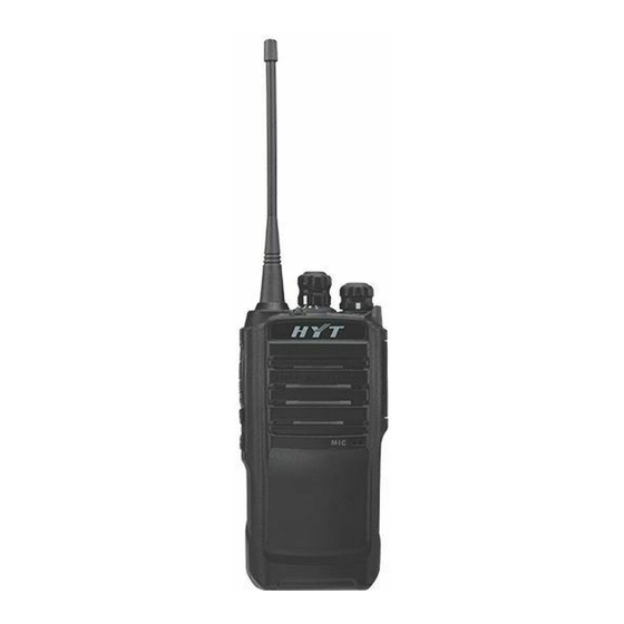
Page 4: Radio Overview
TC-508 Service Manual Radio Overview (1) PTT (Push-to-Talk) (2) SK1 (programmable) (3) SK2 (programmable) (4) Antenna Channel Selector Radio On-Off/Volume (7) Speaker (8) Microphone Knob Control Knob (11) Accessory Jack (9) LED Indicator (10) Battery Latch (12) Accessory Jack Cover... - Page 5 TC-508 Service Manual * PTT (Push-to-Talk) Key Press and hold down the PTT key to transmit, and release it to receive. * SK1 and SK2 The side keys (SK1 and SK2) can be programmed with long/short press functions by your dealer.
- Page 6 TC-508 Service Manual Status of the target radio in Wired The LED glows green during cloning process. Clone mode The green LED goes out once cloning is completed. When the radio is turned on, an alert tone sounds and the Status Indicator flashes orange once.
-
Page 7: Software Specifications
TC-508 Service Manual Software Specifications Description 1. Channel Capacity: 16 2. Channel Spacing: 25KHz/12.5KH 3. Channel Scan 4. RX/TX status indication (red/green LED) 5. CTCSS/CDCSS (38 groups of CTCSS, 83 groups of CDCSS, and CTCSS Tail Invert by 180 degrees.) 6. - Page 8 TC-508 Service Manual Squelch Off Squelch Off Momentary Power Adjust Battery Strength Indicator Voice-operated Transmit (VOX) Channel Lock Description of Modes User Mode It is a conventional communication mode. After the radio is turned on, it enters the User Mode.
- Page 9 TC-508 Service Manual 2. Process 1) The LED flashes red once after the source radio enters Wired Clone Mode. Press PTT to begin to clone data to the target radio. 2) During cloning, LED of the source radio solidly glows red, and LED of the target radio solidly glows green.
- Page 10 TC-508 Service Manual The Status Indicator solidly glows red when adjusting items CH1 to CH9. RX Group Items: CH10-CH13 stand for SQL Normal On, SQL Normal Off, RX Low Voltage Threshold and RX Bandpass Adjustment. Green LED solidly glows when adjusting items CH10 to CH13.
- Page 11 TC-508 Service Manual...
-
Page 12: Circuit Description
TC-508 Service Manual Circuit Description 1. General Diagram The general circuit is composed of TX section, RX section, Power Supply circuit, Control circuit and so on. See the block diagram as shown below: TC-500S Block Diagram B201 SP_JACK PJ-D3027D VR SW... - Page 13 TC-508 Service Manual RX Section: RF signals received via the antenna are fed to the band-pass filter to filter out undesired out-of-band interference signal. Then the remaining RF signals are amplified by LNA Q501. Afterwards, the amplified signal goes through the bandpass filter again to filter out undesired out-of-band interference signal.
- Page 14 TC-508 Service Manual LOCAL OSCILLATOR AMP Q104 2SC5108 BUFFER AMP Q105 2SC4226 T/R SW Q103 D105 LOOP FILTER DATA/STB/CK TX/RX U601 U102 Q102 MB15E03SL SRT3210 QT_MODE Crystal FILLER QT_OUT R103 XT 101 38.4MHz C132 Figure 2 The PLL circuit generates RF carrier signal for TX and the first local oscillator signal for Step frequency of PLL circuit is 6.25 KHz and 5 KHz.
- Page 15 TC-508 Service Manual VR SW POWER AMP POWER AMP D405 Q402 Q403 POWER AMP LOCAL OSCILLATOR AMP RD01 RD07 Q401 Q406 2SC4226 2SC4226 POWER ANT LPF MATCH VT SW D404 LOCAL OSCILLATOR AMP APC_SW Q104 Q404 2SC5108 DTC114YE U401 T/R SW...
- Page 16 TC-508 Service Manual Figure 4 RF signals received via the antenna are fed to the band-pass filter to filter out undesired out-of-band interference signal. Then the remaining RF signals are amplified by LNA Q501. Afterwards, the amplified signal goes through the bandpass filter again to filter out undesired out-of-band interference signal. After being filtered and amplified, the RF signals and first LO signals are mixed at Q502, and then the mixed signal is filtered by crystal filter XF501 to get 38.85MHz differential signals as the first IF signal.
- Page 17 TC-508 Service Manual Figure 5 1) MCU Control Circuit MCU control circuit is composed of MCU, EEPROM, keys and etc. This section has the following functions: to initialize data of the radio and save data to EEPROM; to detect battery voltage and signals from external keys, LD and VOX, and to make response;...
- Page 18 TC-508 Service Manual and transmit/receive data to/from PC. 2) Signal Processing Circuit a. TX Baseband Processing The audio signals input from MIC are divided into two parts. One part enters U601, and is then converted into digital signal by analog-to-digital conversion (ADC). Afterwards, the converted signal will go through a series of processing including low-pass filtering, AGC, companding, high-pass filtering, and pre-emphasizing, and then it will be output as baseband signal after digital-to-analog conversion (DAC).
- Page 19 TC-508 Service Manual VR SW Q604 Q305 U606 V_SAVE U602 U604 V_BAT Figure 6 Power Supply Section: the 7.4V battery voltage is converted to 5V via DC-DC module U604, and further converted via LDO U602 to 3V including two channels: VCC and VDD. VCC powers CPU and VDD powers PLL circuit.
-
Page 20: Cpu Pins
TC-508 Service Manual CPU Pins Port Name Pin Name Function UART TX UART Red APA_EN Control speaker (H: unmute; L: mute) SAVE_CTL Control Power Save; in non-Power-Save status, it is at high level. EXT MIC Check MIC connection (valid for high level) - Page 21 TC-508 Service Manual VSS_CLD Ground power supply for digital PA CLD_OUTM Reserve Negative output of digital PA VCC(3.0V) Vdd_CLD Power supply for digital PA Reserve Reserved P76/DAC1 APC/TU TX power control/RX bandpass control P75/VREF VCC(3.0V) Input pin of reference voltage of ADC and DAC...
- Page 22 TC-508 Service Manual P17/SEG7 Reserve Reserved P20/SEG8 To detect input from encoder switch P21/SEG9 P22/SEG10 P23/SEG11 P24/SEG12 Reserve Reserved P25SEG13 Reserve Reserved P26/SEG14 Reserve Reserved P27/SEG15 Reserve Reserved P30/SEG16 Reserve Reserved P31/SEG17 Reserve Reserved P32/SEG18 Reserve Reserved P33/SEG19 Reserve Reserved...
- Page 23 TC-508 Service Manual SW_P0 Reserve Reserved SW_P1 TX_CTRL Control power supply for TX (transmit at high level) RESET RESET Reset input Vssa Ground power supply for analog circuit Vdda VCC(3.0V) Power supply for analog circuit BG_REF To output reference voltage...
-
Page 24: List
TC-508 Service Manual TC-508 Parts List 1 TC-508 (400-420MHz) Part No. Description Qty. Ref No. Print No. 3001050000000 Chip resistor 0Ω J 1/16W 0402 (RoHS) R222 3001050000000 Chip resistor 0Ω J 1/16W 0402 (RoHS) R442 3001050000000 Chip resistor 0Ω J 1/16W 0402 (RoHS) - Page 25 TC-508 Service Manual Part No. Description Qty. Ref No. Print No. 3001051020000 Chip resistor 1KΩ F 1/16W 0402 (RoHS) R696 3001051020000 Chip resistor 1KΩ F 1/16W 0402 (RoHS) R697 3001051020000 Chip resistor 1KΩ F 1/16W 0402 (RoHS) R698 3001051030000 Chip resistor 10KΩ J 1/16W 0402 (RoHS)
- Page 26 TC-508 Service Manual Part No. Description Qty. Ref No. Print No. 3001052210000 Chip resistor 220Ω J 1/16W 0402 (RoHS) R519 3001052220010 Chip resistor 2.2KΩ F 1/16W 0402 (RoHS) R202 3001052220010 Chip resistor 2.2KΩ F 1/16W 0402 (RoHS) R216 3001052220010 Chip resistor 2.2KΩ F 1/16W 0402 (RoHS)
- Page 27 TC-508 Service Manual Part No. Description Qty. Ref No. Print No. 130 3001054730000 Chip resistor 47KΩ J 1/16W 0402 (RoHS) R312 131 3001054730000 Chip resistor 47KΩ J 1/16W 0402 (RoHS) R320 132 3001054730000 Chip resistor 47KΩ J 1/16W 0402 (RoHS)
- Page 28 TC-508 Service Manual Part No. Description Qty. Ref No. Print No. 174 3101050400010 Chip capacitor 4PF B 50V COG 0402 (RoHS) C568 175 3101050400010 Chip capacitor 4PF B 50V COG 0402 (RoHS) C573 176 3101050500010 Chip capacitor 5PF B 50V COG 0402 (RoHS)
- Page 29 TC-508 Service Manual Part No. Description Qty. Ref No. Print No. 218 3101051020010 Chip capacitor 1000PF K 50V X7R 0402 (RoHS) C126 219 3101051020010 Chip capacitor 1000PF K 50V X7R 0402 (RoHS) C133 220 3101051020010 Chip capacitor 1000PF K 50V X7R 0402 (RoHS)
- Page 30 TC-508 Service Manual Part No. Description Qty. Ref No. Print No. 262 3101051030020 Chip capacitor 0.01UF K 25V X7R 0402 (RoHS) C637 263 3101051030020 Chip capacitor 0.01UF K 25V X7R 0402 (RoHS) C648 264 3101051030020 Chip capacitor 0.01UF K 25V X7R 0402 (RoHS)
- Page 31 TC-508 Service Manual Part No. Description Qty. Ref No. Print No. 306 3101052230000 Chip capacitor 0.022UF K 16V X7R 0402 (RoHS) C642 307 3101052240010 Chip capacitor 0.22UF Z 10V Y5V 0402 (RoHS) C208 308 3101052240010 Chip capacitor 0.22UF Z 10V Y5V 0402 (RoHS)
- Page 32 TC-508 Service Manual Part No. Description Qty. Ref No. Print No. 350 3101054710010 Chip capacitor 470PF K 50V X7R 0402 (RoHS) C633 351 3101054710010 Chip capacitor 470PF K 50V X7R 0402 (RoHS) C636 352 3101054710010 Chip capacitor 470PF K 50V X7R 0402 (RoHS)
- Page 33 TC-508 Service Manual Part No. Description Qty. Ref No. Print No. 394 3104074750070 Tantalum capacitor 4.7UF M 10V P (RoHS) C149 395 3104074750070 Tantalum capacitor 4.7UF M 10V P (RoHS) C201 396 3104074750070 Tantalum capacitor 4.7UF M 10V P (RoHS)
- Page 34 TC-508 Service Manual Part No. Description Qty. Ref No. Print No. 438 3231351650000 Air-core inductor E2-0.35*1.6*5TL (RoHS) L519 439 3231351650000 Air-core inductor E2-0.35*1.6*5TL (RoHS) L520 440 3231351680000 Air-core inductor E2-0.35*1.6*8TR (RoHS) L409 441 3302030500020 Zener diode 18V 150℃ SOD-323 (RoHS)
- Page 35 TC-508 Service Manual Part No. Description Qty. Ref No. Print No. 482 3608015000000 Power management IC Regulators 5V (RoHS) U604 483 3608015000050 Power management IC LDO 4.5V&4.5V 150mA (RoHS) U606 484 3609006000000 Reset IC 2.7V (RoHS) U605 485 3609049000010 Power managementIC LDO 3V 300mA (RoHS)
- Page 36 TC-508 Service Manual 548 3101062700010 Chip capacitor 27PF J 50V COG 0603 (RoHS) C418 549 3104084750040 Tantalum capacitor 1206 4.7uF K 16V (RoHS) C442 550 3104084750040 Tantalum capacitor 1206 4.7uF K 16V (RoHS) C651 551 3104242250000 Tantalum capacitor 2.2UF K 16V A (RoHS)
- Page 37 TC-508 Service Manual TC-508 (450-470MHz) Part No. Description Qty. Ref No. Print No. 3001050000000 Chip resistor 0Ω J 1/16W 0402 (RoHS) R222 3001050000000 Chip resistor 0Ω J 1/16W 0402 (RoHS) R442 3001050000000 Chip resistor 0Ω J 1/16W 0402 (RoHS) R511 3001050000000 Chip resistor 0Ω...
- Page 38 TC-508 Service Manual Part No. Description Qty. Ref No. Print No. 3001051020000 Chip resistor 1KΩ F 1/16W 0402 (RoHS) R697 3001051020000 Chip resistor 1KΩ F 1/16W 0402 (RoHS) R698 3001051030000 Chip resistor 10KΩ J 1/16W 0402 (RoHS) R103 3001051030000 Chip resistor 10KΩ J 1/16W 0402 (RoHS) R107 3001051030000 Chip resistor 10KΩ...
- Page 39 TC-508 Service Manual Part No. Description Qty. Ref No. Print No. 3001052220010 Chip resistor 2.2KΩ F 1/16W 0402 (RoHS) R202 3001052220010 Chip resistor 2.2KΩ F 1/16W 0402 (RoHS) R216 3001052220010 Chip resistor 2.2KΩ F 1/16W 0402 (RoHS) R507 3001052220010 Chip resistor 2.2KΩ F 1/16W 0402 (RoHS) R510 3001052230010 Chip resistor 22KΩ...
- Page 40 TC-508 Service Manual Part No. Description Qty. Ref No. Print No. 132 3001054730000 Chip resistor 47KΩ J 1/16W 0402 (RoHS) R417 133 3001054730000 Chip resistor 47KΩ J 1/16W 0402 (RoHS) R553 134 3001054730000 Chip resistor 47KΩ J 1/16W 0402 (RoHS) R610 135 3001054730000 Chip resistor 47KΩ...
- Page 41 TC-508 Service Manual Part No. Description Qty. Ref No. Print No. 176 3101050400010 Chip capacitor 4PF B 50V COG 0402 (RoHS) C573 177 3101050500010 Chip capacitor 5PF B 50V COG 0402 (RoHS) C118 178 3101050590020 Chip capacitor 0.5PF B 50V C0G 0402 (RoHS) C109 179 3101050590020 Chip capacitor 0.5PF B 50V C0G 0402 (RoHS)
- Page 42 TC-508 Service Manual Part No. Description Qty. Ref No. Print No. 220 3101051020010 Chip capacitor 1000PF K 50V X7R 0402 (RoHS) C126 221 3101051020010 Chip capacitor 1000PF K 50V X7R 0402 (RoHS) C133 222 3101051020010 Chip capacitor 1000PF K 50V X7R 0402 (RoHS)
- Page 43 TC-508 Service Manual Part No. Description Qty. Ref No. Print No. 264 3101051030020 Chip capacitor 0.01UF K 25V X7R 0402 (RoHS) C637 265 3101051030020 Chip capacitor 0.01UF K 25V X7R 0402 (RoHS) C648 266 3101051030020 Chip capacitor 0.01UF K 25V X7R 0402 (RoHS) C649 267 3101051030020 Chip capacitor 0.01UF K 25V X7R 0402 (RoHS)
- Page 44 TC-508 Service Manual Part No. Description Qty. Ref No. Print No. 308 3101052200010 Chip capacitor 22PF J 50V C0G 0402 (RoHS) C526 309 3101052200010 Chip capacitor 22PF J 50V C0G 0402 (RoHS) C594 310 3101052230000 Chip capacitor 0.022UF K 16V X7R 0402 (RoHS) C572 311 3101052230000 Chip capacitor 0.022UF K 16V X7R 0402 (RoHS)
- Page 45 TC-508 Service Manual Part No. Description Qty. Ref No. Print No. 352 3101054710010 Chip capacitor 470PF K 50V X7R 0402 (RoHS) C626 353 3101054710010 Chip capacitor 470PF K 50V X7R 0402 (RoHS) C632 354 3101054710010 Chip capacitor 470PF K 50V X7R 0402 (RoHS)
- Page 46 TC-508 Service Manual Part No. Description Qty. Ref No. Print No. 396 3104074750070 Tantalum capacitor 4.7UF M 10V P (RoHS) C140 397 3104074750070 Tantalum capacitor 4.7UF M 10V P (RoHS) C149 398 3104074750070 Tantalum capacitor 4.7UF M 10V P (RoHS) C201 399 3104074750070 Tantalum capacitor 4.7UF M 10V P (RoHS)
- Page 47 TC-508 Service Manual Part No. Description Qty. Ref No. Print No. 440 3302030500020 Zener diode 18V (RoHS) D655 441 3303240000000 Switching diode 75V 200mA 1.25V 6ns (RoHS) D104 442 3303990000060 Switching diode 35V 100mA 1V (RoHS) D404 443 3303990000060 Switching diode 35V 100mA 1V (RoHS)
- Page 48 TC-508 Service Manual Part No. Description Qty. Ref No. Print No. 484 3609006000000 Reset IC 2.7V (RoHS) U605 485 3609049000010 Power management IC 3V 300mA (RoHS) U602 486 3610999000060 SCM 100Pin H7 (RoHS) U601 487 3612031000510 Memory EEPROM 16KB 1.8~5.5V (RoHS) U603 488 3701038450000 Crystal oscillator 38.4MHz ±3ppm 2.8V (RoHS)
- Page 49 TC-508 Service Manual Part No. Description Qty. Ref No. Print No. 528 3104084750040 Tantalum capacitor 1206 4.7uF K 16V (RoHS) C651 529 3104242250000 Tantalum capacitor 2.2UF K 16V A (RoHS) C115 530 3104242250000 Tantalum capacitor 2.2UF K 16V A (RoHS) C420 531 3210306820000 Multi-layer chip inductor 82nH J 300mA 0.85ohm 0603 (RoHS)
-
Page 50: Adjustment Description
TC-508 Service Manual Adjustment Description Required Test Instruments: Radio communication test set (HP8921) 1 set 10V/3A regulated DC power supply 1 set Digital Voltmeter 1 set Ammeter 1 set Preparation Place the board to be tested on the test fixture (please ensure good connection between each test point and the fixture), and connect the board to a power supply with DC voltage of 7.4V. - Page 51 TC-508 Service Manual (151.4Hz) CTCSS Deviation (high) (254.1Hz) TX Low Voltage Threshold Max. Deviation of TX Audio SQL Normal SQL Normal RX Low Voltage Threshold BPF Tune Y indicates frequencies available for tuning, and the rest are blank channels without tuning items.
- Page 52 TC-508 Service Manual frequency respectively. Make sure the antenna or load is connected before adjustment.) Test Adjustment Specification/ Item Condition Test Test Part Method Remarks Instrument point Adjust VR101 with ceramic Rotate the Channel tuning tool to TX Frequency Selector knob to...
- Page 53 TC-508 Service Manual Short press Selector PTT key to Knob to save switch among different frequencies (low, medium and high) Rotate Channel Press Selector Knob SK1/SK2 to CH1 and adjust select output power, frequency. and rotate the 2W±0.3W Short press I≤1A...
- Page 54 TC-508 Service Manual “wide until the bandwidth” CDCSS “low deviation frequency” meets the are selected. requirements. Short press PTT key to switch among different frequencies (low, medium and high) Long press PTT to enter the narrow Press band and SK1/SK2 to...
- Page 55 TC-508 Service Manual channel. On CH5, CH6 and CH7, long Press press SK1/SK2 to key to enter make slight “narrow adjustments Narrow bandwidth”, until the 350~550Hz Bandwidth short CDCSS press deviation key to switch meets the among requirements. different frequencies.
- Page 56 TC-508 Service Manual frequencies (low, medium and high). Rotate Channel Selector Knob to CH9, wide bandwidth frequency are selected; short press PTT to switch among Communication different Test Set frequencies Modulation Wide (low, medium BPF: Check 3.0KHz and high). Sensitivity Bandwidth <20Hz~15kHz...
- Page 57 TC-508 Service Manual Communicati Long press SK to enter on Test Set “narrow band”. Press SSG:-121dB Squelch level Narrow [+] and [-] key to adjust Same (Level 5): Bandwi MOD:1KHz -121±1dBm squelch level. Short above. DEV:1.5KHz press PTT key to Filter: 0.3~...
- Page 58 TC-508 Service Manual five-point adjustment. Appendix 1: Reference Value for TC-508 Source Radio Wide Bandwidth Narrow Bandwidth Tuning Item TX Power L TX Power H CDCSS Balance (DA port) Waveform CDCSS Deviation(mode port) CTCSS Deviation(67Hz) (low) CTCSS Deviation (151.4Hz)(medium) CTCSS Deviation (254.1Hz)...
-
Page 59: Troubleshooting Flow Chart
TC-508 Service Manual Troubleshooting Flow Chart Transmit Circuit Start Low TX LED fails to Replace No sound power Transmission glow/flash. D604. Normal TX Check the TX power supply? power supply. Check the voice channel (Output ports of LED of D604... - Page 60 TC-508 Service Manual Receiver Circuit...
- Page 61 TC-508 Service Manual Start Normal power-on alert? The speaker Replace the works normally? speaker. Normal VCC Check U601, (operating voltage of U602, U604, and MCU)? U606. Clock crystal (X601) of MCU works Replace X601. normally? Check the pins Other pins control...
-
Page 62: Disassembly And Assembly
TC-508 Service Manual Disassembly and Assembly Disassembling the Chassis Remove the Antenna , the Channel Selector knob and Radio On -Off/Volume Control knob ① ② ③ Use a spanner to remove the fixing nuts ④ Unfasten the two screws by a screwdriver ⑤... - Page 63 TC-508 Service Manual Screw 螺钉 Speaker fixing sheet 喇叭 压片 Figure 9 Disassembling the TX and RX Units 1. Power off the radio at first, and then remove the belt clip, battery and antenna one by one; 2. Unfasten the screws on the PCB in the direction of and on the PTT keyboard in the direction of ⑥...
- Page 64 TC-508 Service Manual Figure 10 Precautions for Re-assembly Assembling the Chassis and the Aluminum Chassis 1. Insert the speaker to the front case. 2. Attach the fixing sheet to the speaker with screw. 3. Make sure the waterproof ring surrounding the chassis is well fitted into the slot.
-
Page 65: Exploded View
TC-508 Service Manual Exploded View... -
Page 66: List
TC-508 Service Manual TC-508 Parts List 2 Part No Description (PCS). 6001139000000 Front case 6100312000010 Silicone rubber PTT key 6000842100010 Plastic PTT key 7101904020200 Self-tapping screw ST1.94.0mm PCB main board 6100542100000 Waterproof ring for radio 6300115000000 Aluminum chassis 7102508000010 Machine screw M2.58.0mm... -
Page 67: Pcb View
TC-508 Service Manual TC-508 PCB View TC-508 Level Diagram TC-508 Block Diagram TC-508 Schematic Diagram... -
Page 68: Specifications
TC-508 Service Manual Specifications General 400-420MHz, 450-470MHz Frequency Range 136-154MHz,146-174MHz Channel Capacity Channel Spacing 25 KHz /12.5KHz Operating Voltage 7.4V DC Operating Temperature -25℃~+60℃ Dimensions (H×W×D) 113*54*32mm (with standard battery, without antenna) 250g Weight (with antenna & battery) Frequency Stability ±2.5ppm...
Need help?
Do you have a question about the TC-508 and is the answer not in the manual?
Questions and answers