
Summary of Contents for Hornby R8213
- Page 1 Hornby Hobbies Limited, Margate, Kent CT9 4JX. Tel: +44 (0) 1843 233525 www.hornby.com ‘Select’ Unit - Operators Manual For more information visit: M4642E...
-
Page 2: Table Of Contents
Walkabout Mode Master Select Connected to Select ‘walkabout’ Units Welcome to the digital Hornby World of model railways.You are about to enjoy a new and exciting experience when it comes to controlling and operating a model railway. Speed Step Change Using the keypad that is on the Select unit locomotives can be “called up”... -
Page 3: About Dcc Select
Default loco 03. This is a system check to ensure that the Select is functioning correctly. Note: All Digital locomotives included in Hornby Digital sets are factory fitted with Decoders. These Decoders are programmed No. 3 as standard (default). Note: Hornby offer locomotive which are either DCC ready or DCC fitted. -
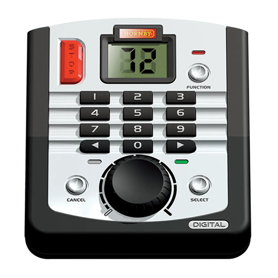
Page 4: Lcd Display
Select. Ensure the track and connecting fishplates are clean and all fishplates are secure. Display Display It is also advisable to secure the track using R207 Hornby Track Pins to prevent movement and loose connections. Connecting the Digital Control Unit... -
Page 5: Quick Start
The red LED will flash up to seven times during which the decoder will be accepting the new address. If the LED flashes eight times, it is advisable to reprog ramme the Decoder ag ain. 5.The locomotive is now programmed as No. 1. www.hornby.com For more information visit:... -
Page 6: Throttle Control
Choose the locomotives address on the keypad. The LCD will now flash the locomotives address. It is possible to have more than one locomotive running on the same track at the same time with the Hornby Press and release Direction button . -
Page 7: Emergency Stop
The locomotive will now move off in the corresponding direction. This procedure can be used when for operational reasons on a layout it would be more convenient if the lcomotve ran in the opposite direction from what is considered "default." www.hornby.com For more information visit:... -
Page 8: Double/Triple Heading
When the Consist is dissolved the levels of acceleration and deceleration will remain at the levels set instructions as per pag e 8. Note: When the Consist is dissolved the levels of acceleration and during the Consist. deceleration will remain at the levels set during Consist. www.hornby.com For more information visit:... -
Page 9: Analogue Locomotive Control
“FUNCTION” button. The function will turn ON or OFF depending on it's current state. The display will then show for about 3 seconds either “On” or “oF” confirming the function action you have just carried out. The display will then revert to loco address. www.hornby.com For more information visit:... -
Page 10: How Many Locos Can The Select Run
Press “SELECT” to confirm your choice. Please contact your Hornby dealer or Customer Care for more information regarding the use of Boosters and The RED LED will ash 5 times to con rm the setting s. how to connect them to your layout. -
Page 11: Walkabout Mode
“Stop” position. The Select may also be used with the Hornby ELITE advanced controller as a "walkabout." However, it should be remembered that the Select is preprogrammed with address ranges for locomotives (1-59) Operation 2 - Controlling two or more different locomotives and accessories (61-99) which may not be suitable for operations with your ELITE system and layout. -
Page 12: Master Select Connected To Select 'Walkabout' Units
Only connect power to the Master Controller. R8266 R8237 DO NOT CONNECT POWER TO ANY ‘walkabout’ SELECT Note: Only the designated "Master" Select is connected to the track. ‘walkabout’ Units ‘walkabout’ Units ‘walkabout’ Units ‘walkabout’ Units www.hornby.com For more information visit:... -
Page 13: Speed Step Change
The Select by default divides the full speed range for a locomotive decoder into 128 discrete speed steps. This When addressing locomotives and Hornby Point/Accessory Decoders it is important that all other locomotives are removed from the track. It is also important that all point decoders are disconnected from the layout. -
Page 14: Programming Track
The four function R8249 Hornby Digital Decoder features: The Hornby Select Digital Control is capable of operating up to 39 points or solenoid operated accessories when used in conjunction with the Hornby R8247 Points Decoder Module. The Point Decoder Module can Load compensation (Back EMF): Locomotive will run at a consistent speed either on the “flat”... -
Page 15: Making Points 'Live
It is possible to change the rate at which a locomotive accelerates via programming functions of the controller. Hornby points are self isolating therefore it is necessary to fit each point with 2 x R8232 Hornby DCC See page 10. -
Page 16: Glossary
Locomotive Decoders can be fitted to accessories that have a motor as a drive such as the R8131 Hornby motor is known as the ‘Stall Current’. -
Page 17: Trouble Shooting
Make sure that a locomotive has not been given a new address while other locomotives have been on the same track.To avoid this it is advisable to use a Programming Track to add new addresses to locomotives and Hornby Overload indication Select and 4 Amp power supply. -
Page 18: Safety Notes
Before use the transformer should be examined for damage to the casing, plug pins and cables. In the event of such The Select display is dim or looks wrong? damage, the Select unit should not be used until the transformer is replaced with a new Hornby recommended unit. Never attempt to open the unit yourself.
Need help?
Do you have a question about the R8213 and is the answer not in the manual?
Questions and answers