Advertisement
Quick Links
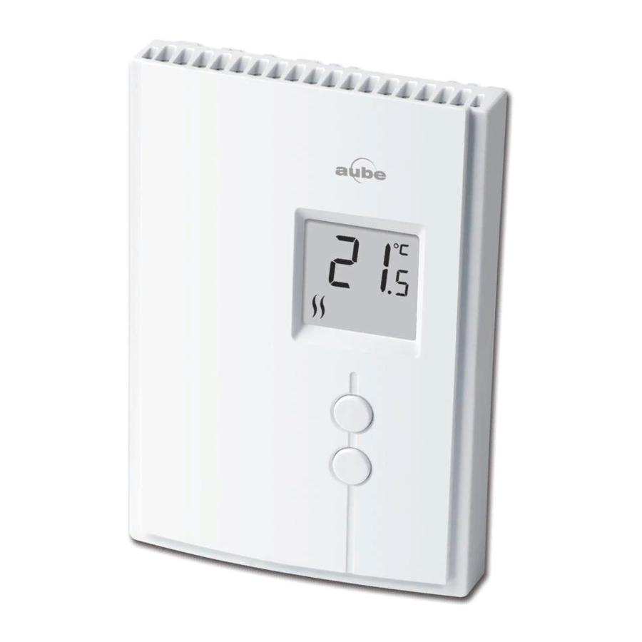
Heating intensity
indicator. No image
appears when
heating is off.
Description
This thermostat can be used to control an electric heating system
such as a baseboard heater, a radiant floor,a radiant ceiling, or a con-
vector.
The thermostat CANNOT be used with:
•
a resistive load under 0.83 A
•
a resistive load over 8.3 A
•
a system driven by a contactor or a relay (inductive load)
•
a fan-forced heating system (e.g. : fan-forced convector)
•
a central heating system
SUPPLIED PARTS
•
One (1) thermostat
•
Two (2) 6-32 mounting screws
•
Two (2) solderless connectors
Installation
TURN OFF POWER OF THE HEATING SYSTEM AT THE MAIN
POWER PANEL TO AVOID ELECTRIC SHOCK.
Loosen the screw holding the faceplate to the base. The screw can-
not be completely removed and remains captive on the base.
Remove the faceplate from the base by pulling the bottom half.
TH209
Temperature display
Temperature
}
Up button
adjustment
Down button
buttons
1.
2.
Connect any one of thermostat wires to the heater (load) wire and the
other one to the power supply wire using solderless connectors for
copper wires. (The thermostat wires are non-polarized; either wire
can be connected to the load or to the power supply.)
NOTE:
All cables and connections must conform to the local electri-
cal code. Special CO/ALR solderless connectors must be used when
connecting with aluminium conductors.
2-wire installation
4-wire installation
Install the base onto an electrical
box.
Reinstall the faceplate on the base
and secure it in place with the screw.
NOTE: Keep the air vents of thermo-
stat clean and unobstructed at all
times.
400-209-000-A
TH209
User Guide
Electronic Thermostat
2008-06-19
1/2
Advertisement

Related Manuals for Aube Technologies TH209


Summary of Contents for Aube Technologies TH209
-
Page 1: User Guide
Remove the faceplate from the base by pulling the bottom half. TH209 Connect any one of thermostat wires to the heater (load) wire and the other one to the power supply wire using solderless connectors for copper wires. (The thermostat wires are non-polarized; either wire Temperature display can be connected to the load or to the power supply.) -
Page 2: Troubleshooting
Press the Up and Down buttons for one second (or wait for one minute) to return to the normal display. Temperature Display and Setting The thermostat normally displays the actual (ambient) temperature. • To view the setpoint temperature, press once on either temperature adjustment button.
Need help?
Do you have a question about the TH209 and is the answer not in the manual?
Questions and answers
nº TH209|Nº UGS 1000536256 how to unlock ??