Table of Contents
Advertisement
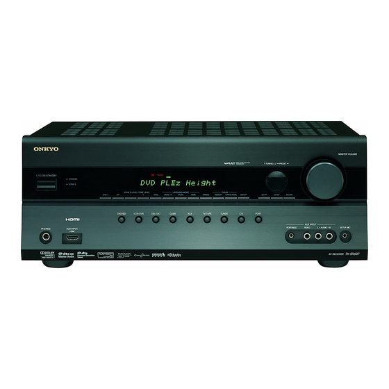
AV Receiver
TX-SR607
Instruction Manual
Thank you for purchasing an Onkyo AV Receiver.
Please read this manual thoroughly before making
connections and plugging in the unit.
Following the instructions in this manual will enable
you to obtain optimum performance and listening
enjoyment from your new AV Receiver.
Please retain this manual for future reference.
Contents
Introduction ...................................2
Connection ..................................15
Turning On & First Time Setup .....38
Basic Operations.........................51
Using the Listening Modes ........62
Advanced Setup ..........................69
Zone 2
.........................................85
Controlling Other Components ....89
Others.........................................100
E
n
Advertisement
Table of Contents

Related Manuals for Onkyo TX SR607


Summary of Contents for Onkyo TX SR607
- Page 1 AV Receiver TX-SR607 Instruction Manual Thank you for purchasing an Onkyo AV Receiver. Please read this manual thoroughly before making connections and plugging in the unit. Following the instructions in this manual will enable you to obtain optimum performance and listening enjoyment from your new AV Receiver.
-
Page 2: Important Safety Instructions
WARNING: TO REDUCE THE RISK OF FIRE OR ELECTRIC SHOCK, DO NOT EXPOSE THIS APPARATUS TO RAIN OR MOISTURE. CAUTION: TO REDUCE THE RISK OF ELECTRIC SHOCK, DO NOT REMOVE COVER (OR BACK). NO USER-SERVICEABLE PARTS INSIDE. REFER SERVICING QUALIFIED PERSONNEL. -
Page 3: Precautions
7. Never Touch this Unit with Wet Hands—Never handle this unit or its power cord while your hands are wet or damp. If water or any other liquid gets inside this unit, have it checked by your Onkyo dealer. 8. Handling Notes •... -
Page 4: Declaration Of Conformity
We, ONKYO EUROPE ELECTRONICS GmbH LIEGNITZERSTRASSE 6, 82194 GROEBENZELL, GERMANY declare in own responsibility, that the ONKYO product described in this instruction manual is in compliance with the corresponding technical standards such as EN60065, EN55013, EN55020 and EN61000-3-2, -3-3. GROEBENZELL, GERMANY... -
Page 5: Features
Audyssey 2EQ Audyssey Dynamic Volume are trademarks of Audyssey Laboratories. *8. Music Optimizer™ is a trademark of Onkyo Corporation. Apple and iPod are trademarks of Apple Inc., registered in the U.S. and other countries. “x.v.Color” is a trademark of Sony Corporation. -
Page 6: Multiroom Capability
Multiroom Capability You can use two speaker systems with this AV receiver—a surround-sound speaker system (up to 7.1 channels) in your main listening room, a stereo speaker system in a second room, or Zone 2, as we call it. And, you can select a different audio source for each room. -
Page 7: Table Of Contents
Connecting an RI Dock ... 36 Connecting a Dock with the Universal Port connector ... 36 Connecting Onkyo u Components ... 37 Connecting the Power Cord ... 37 Turning On & First Time Setup Turning On the AV Receiver ... 38 Turning On and Standby ... -
Page 8: Front & Rear Panels
Front & Rear Panels Front Panel North American/Taiwan models g h i j k l m n Other models The actual front panel has various logos printed on it. They are not shown here for clarity. -
Page 9: Aux Input
Front & Rear Panels—Continued The page numbers in parentheses show where you can find the main explanation for each item. a ON/STANDBY button (38) This button is used to set the AV receiver to On or Standby. b STANDBY indicator (38) This indicator lights up when the AV receiver is in Standby mode, and it flashes while a signal is being received from the remote controller. -
Page 10: Display
Front & Rear Panels—Continued Display For detailed information, see the pages in parentheses. a SLEEP indicator (53) Lights up when the Sleep function has been set. b MUTING indicator (53) Flashes while the AV receiver is muted. c Listening mode and format indicators (62) Show the selected listening mode and audio input signal format. -
Page 11: Rear Panel
Front & Rear Panels—Continued Rear Panel North American/Taiwan models a b c l m n o p q r s Other models a DIGITAL IN COAXIAL 1 and 2 These coaxial digital audio inputs are for connect- ing components with coaxial digital audio outputs, such as CD and DVD players. - Page 12 REMOTE CONTROL This u (Remote Interactive) jack can be con- nected to an u jack on another Onkyo AV compo- nent. The AV receiver’s remote controller can then be used to control that component. To use u, you...
-
Page 13: Remote Controller
Onkyo component without u connection, point the remote controller at the other component to use it. • When you want to operate an Onkyo component with u connection or an -compatible compo- nent connected via HDMI (page 93), point the remote controller at the AV receiver’s remote control sensor. -
Page 14: Controlling The Av Receiver
Used to select radio presets. Number buttons (54) Used to select radio stations directly in the Direct tuning mode. Also you can select a preset directly. Note: An Onkyo cassette recorder connected via u can also be controlled in Receiver mode (see page 99). -
Page 15: About Home Theater
With DVDs you can enjoy DTS and Dolby Digital. With analog or digital TV, you can enjoy Dolby Pro Logic IIx, DTS Neo:6, or Onkyo’s original DSP listening modes. -
Page 16: Connecting The Av Receiver
Connecting the AV Receiver Connecting Your Speakers Speaker Configuration For 7.1-channel surround-sound playback, you need seven speakers and a powered subwoofer. The following table indicates the channels you should use depending on the number of speakers that you have. Number of speakers: ✓... -
Page 17: Speaker Connection Precautions
Connecting the AV Receiver—Continued Speaker Connection Precautions Read the following before connecting your speakers: • North American/Taiwan models: You can connect speakers with an impedance of between 6 and 16 ohms. If you use speakers with a lower impedance, and use the amplifier at high volume levels for a long period of time, the built-in amp protection circuit may be activated. - Page 18 Connecting the AV Receiver—Continued The following illustration shows which speaker should be connected to each pair of terminals. If you’re using only one surround back speaker, connect it to the left (L) SURR BACK SPEAKERS terminals. ■ North American/Taiwan models ■...
-
Page 19: Bi-Amping The Front Speakers
Connecting the AV Receiver—Continued Bi-amping the Front Speakers The FRONT L/R and SURR BACK L/R terminal posts can be used with front speakers and surround back speakers respectively, or bi-amped to provide separate tweeter and woofer feeds for a pair of front speakers that support bi-amping, providing improved bass and treble performance. -
Page 20: Connecting Antenna
Connecting the AV Receiver—Continued Connecting Antenna This section explains how to connect the supplied indoor FM antenna and AM loop antenna, and how to connect commercially available outdoor FM and AM antennas. The AV Receiver won’t pick up any radio signals with- out any antenna connected, so you must connect the antenna to use the tuner. -
Page 21: Connecting An Outdoor Fm Antenna
Connecting the AV Receiver—Continued Connecting an Outdoor FM Antenna If you cannot achieve good reception with the supplied indoor FM antenna, try a commercially available out- door FM antenna instead. Notes: • Outdoor FM antennas work best outside, but usable results can sometimes be obtained when installed in an attic or loft. -
Page 22: About Av Connections
Connecting the AV Receiver—Continued About AV Connections • Before making any AV connections, read the manuals supplied with your other AV components. • Don’t connect the power cord until you’ve completed and double-checked all AV connections. Optical Digital Jacks The AV receiver’s optical digital jacks have shutter-type covers that open when an optical plug is inserted and close when it’s removed. -
Page 23: Connecting Components With Hdmi
■ Onkyo for System Control , which stands for Remote Interactive over HDMI, is the name of the system control function found on Onkyo components. The AV receiver can be used with CEC (Consumer Electronics Control), which allows system control over HDMI and is part of the HDMI standard. -
Page 24: Making Hdmi Connections
Connecting the AV Receiver—Continued Making HDMI Connections Step 1: Use HDMI cables to connect the AV receiver’s HDMI jacks to your HDMI-compatible Blu-ray player/DVD player, TV, projector, and so on. Step 2: Assign each HDMI IN to an input selector in the HDMI Input Setup (see page 40). ■... -
Page 25: Connecting Both Audio & Video
Connecting the AV Receiver—Continued Connecting Both Audio & Video By connecting both the audio and video outputs of your DVD player and other AV components to the AV receiver, you can select both the audio and video simultaneously simply by selecting the appropriate input source on the AV receiver. : Signal Flow Video Audio... - Page 26 Connecting the AV Receiver—Continued ■ Signal Selection If signals are present at more than one input, the inputs will be selected automatically in the fol- lowing order of priority: HDMI, component video, composite video. However, for component video only, regardless of whether a component video signal is actually present, if a component video input is assigned to the input selector, that component video input...
-
Page 27: Connecting A Tv Or Projector
Connecting the AV Receiver—Continued Connecting a TV or Projector See “Connecting Components with HDMI” on page 23 for HDMI connection information. Step 1: Video Connection Choose a video connection that matches your TV ( Step 2: Audio Connection Choose an audio connection that matches your TV ( , The onscreen setup menus appear only on a TV that is connected to the HDMI OUT. -
Page 28: Connecting A Dvd Player
Connecting the AV Receiver—Continued Connecting a DVD Player See “Connecting Components with HDMI” on page 23 for HDMI connection information. Step 1: Video Connection Choose a video connection that matches your DVD player ( You must connect the AV receiver to your TV via the same type of connection. Step 2: Audio Connection Choose an audio connection that matches your DVD player ( , •... -
Page 29: Connecting A Vcr Or Dvd Recorder For Playback
Connecting the AV Receiver—Continued Connecting a VCR or DVD Recorder for Playback With this hookup, you can use your VCR’s tuner to listen to your favorite TV programs via the AV Hint! receiver, useful if your TV has no audio outputs. Step 1: Video Connection Choose a video connection that matches your VCR or DVD recorder ( must connect the AV receiver to your TV via the same type of connection. -
Page 30: Connecting A Vcr Or Dvd Recorder For Recording
Connecting the AV Receiver—Continued Connecting a VCR or DVD Recorder for Recording Step 1: Video Connection Make the video connection type of connection. Step 2: Audio Connection Make the audio connection Connection VCR/DVR OUT V VCR/DVR OUT L/R Notes: • The AV receiver must be turned on for recording. Recording is not possible while it’s in Standby mode. •... -
Page 31: Connecting A Satellite, Cable, Terrestrial Set-Top Box, Or Other Video Source
Connecting the AV Receiver—Continued Connecting a Satellite, Cable, Terrestrial Set-top box, or Other Video Source With this hookup, you can use your satellite or cable receiver to listen to your favorite TV programs Hint! via the AV receiver, useful if your TV has no audio outputs. Step 1: Video Connection Choose a video connection that matches the video source ( You must connect the AV receiver to your TV via the same type of connection. -
Page 32: Connecting A Game Console
Connecting the AV Receiver—Continued Connecting a Game Console Step 1: Video Connection Choose a video connection that matches the game console ( You must connect the AV receiver to your TV with the same type of connection. Step 2: Audio Connection Choose an audio connection that matches the game console ( •... -
Page 33: Connecting A Camcorder Or Other Device
Connecting the AV Receiver—Continued Connecting a Camcorder or Other Device Step 1: Video Connection Make the connection Step 2: Audio Connection Make the connection Camcorder, etc. Connection AV receiver AUX INPUT VIDEO AUX INPUT L-AUDIO-R Connecting a Portable Audio player Step 1: Make the audio connection AUX INPUT PORTABLE... -
Page 34: Connecting A Cd Player Or Turntable
Connecting the AV Receiver—Continued Connecting a CD Player or Turntable ■ CD Player or Turntable (MM) with Built-in Phono Preamp Step 1: Choose a connection that matches your CD player ( , phono preamp. Connect one or the other Con- nection must be assigned... -
Page 35: Connecting A Cassette, Cdr, Minidisc, Or Dat Recorder
Connecting the AV Receiver—Continued Connecting a Cassette, CDR, MiniDisc, or DAT Recorder Step 1: Choose a connection that matches the recorder ( , OPTICAL IN 1 (GAME) COAXIAL IN 2 (CBL/SAT) Connect one or the other Connection must be assigned (see page 42) •... -
Page 36: Connecting An Ri Dock
Connect your RI Dock’s audio output jacks to the AV receiver’s GAME IN or VCR/DVR IN L/R jacks, and connect its video output jack to the AV receiver’s GAME IN or VCR/DVR IN V jack. (Onkyo DS-A2 hookup shown below.) GAME... -
Page 37: Connecting Onkyo U Components
• Some components have two u jacks. You can con- nect either one to the AV receiver. The other jack is for connecting additional u-capable components. • Connect only Onkyo components to u jacks. Con- necting other manufacturer’s components may cause a malfunction. -
Page 38: Turning On The Av Receiver
If you have, see “HDMI Input Setup” on page 40, “Component Video Setup” on page 41, or “Digital Input Setup” on page 42 respectively. ■ Have you connected an Onkyo MD recorder, CD recorder, or RI Dock? If you have, see “Changing the Input Display” on page 45. -
Page 39: First Time Setup
First Time Setup This section explains the settings that you need to make before using the AV receiver for the very first time. ENTER SETUP Using the Onscreen Setup Menus Carry out the settings for the AV receiver by using the Onscreen Setup Menu. -
Page 40: Video Input Setup
First Time Setup—Continued Video Input Setup HDMI Input Setup If you connect a video component to HDMI IN, you must assign that input to an input selector. For example, if you connect your DVD player to HDMI IN1, you must assign HDMI IN1 to the DVD/BD input selector. -
Page 41: Component Video Setup
First Time Setup—Continued Component Video Setup If you connect to a COMPONENT VIDEO IN, you must assign it to an input selector. For example, if you connect your DVD player to COMPONENT VIDEO IN 2, you should assign it to the DVD/BD input selector. Input selector Default assignment DVD/BD... -
Page 42: Digital Input Setup
First Time Setup—Continued Digital Input Setup If you connect a component to a digital input jack, you must assign that jack to an input selector. For example, if you connect your CD player to the OPTICAL IN1 jack, you should assign that jack to the CD input selector. By default, the COAXIAL IN1 jack is assigned to the DVD/ BD input selector, although this can be changed. -
Page 43: Speaker Settings
First Time Setup—Continued Speaker Settings If you change these settings, you must run the Audyssey 2EQ™ Room Correction and Speaker Setup again (see page 46). If the impedance of any speaker is 4 ohms or more but less than 6, set the minimum speaker impedance to 4 ohms. -
Page 44: Tv Format Setup (Not North American Models)
First Time Setup—Continued TV Format Setup (not North American models) For the onscreen setup menus to display properly, you must specify the TV system used in your area. Press the [RECEIVER] button fol- lowed by the [SETUP] button. The main menu appears onscreen. If the main menu doesn’t appear, make sure the appropriate external input is selected on your TV. -
Page 45: Changing The Input Display
[SETUP] button, arrow buttons, and [ENTER] button. Changing the Input Display If you connect an u-capable Onkyo MiniDisc recorder, CD recorder, or RI Dock to the TV/TAPE IN/ OUT jacks, or connect an RI Dock to the GAME IN or VCR/DVR IN jacks, for u to work properly, you must change this setting. -
Page 46: Audyssey 2Eq™ Room Correction And Speaker Setup
First Time Setup—Continued ™ Audyssey 2EQ Room Correction and Speaker Setup With the supplied calibrated microphone, Audyssey 2EQ automatically determines the number of speakers connected, their size for purposes of bass management, optimum crossover frequencies to the subwoofer (if present), and distances from the primary listening position. - Page 47 First Time Setup—Continued ™ Using Audyssey 2EQ STANDBY/ON Speaker setup microphone ENTER Notes: • If any of your speakers is 4 ohms, change the “Speaker Impedance” setting before running the Audyssey 2EQ Room Correction and Speaker Setup (see page 43). •...
- Page 48 First Time Setup—Continued • Make the room as quiet as possible. Background noise can disrupt the room measurements. Close windows, silence cell phones, televisions, radios, air conditioners, fluorescent lights, home appliances, light dimmers, or other devices. • Cell phones should be turned off or placed away from all audio electron- ics during the measurement process as Radio Frequency Interference...
-
Page 49: Error Messages
First Time Setup—Continued Disconnect the speaker setup microphone. 2EQ: Auto Setup Please unplug setup microphone. Notes: • When the room correction and speaker setup is complete, the “Equalizer Settings” (page 72) will be set to “Audyssey” and the “Dynamic EQ” (page 74) will be set to “On”. -
Page 50: Using A Powered Subwoofer
This message appears if saving fails. Try saving again. If this message appears after 2 or 3 attempts, the AV receiver is probably malfunctioning. Contact your Onkyo dealer. Retry: Return to step 2 and try again. Cancel: Cancel the room correction and speaker setup. -
Page 51: Basic Operations
Basic Operations Selecting the Input Source This section explains how to select the input source (i.e., the AV component that you want to listen to or watch). INPUT SELECTOR AV receiver Remote controller AV receiver Remote controller MASTER VOLUME Use the AV receiver’s input selector buttons to select the input source. -
Page 52: Adjusting The Bass & Treble
Basic Operations—Continued –, +, TONE Press [RECEIVER] first DIMMER Adjusting the Bass & Treble You can adjust the bass and treble for the front speakers, except when the Direct, Pure Audio listening mode is selected. Press the [TONE] button repeat- edly to select either “Bass”... -
Page 53: Muting The Av Receiver
Basic Operations—Continued Muting the AV receiver You can temporarily mute the output of the AV receiver. Press the [RECEIVER] button, and then press the [MUTING] but- ton. The output is muted and the MUTING indicator flashes on the display, as shown. -
Page 54: Listening To The Radio
Listening to the Radio Using the Tuner With the built-in tuner you can enjoy AM and FM radio stations. You can store your favorite stations as presets for quick selection. TUNING MODE TUNER Listening to the Radio Use the [TUNER] input selector button to select either AM or FM. -
Page 55: Presetting Am/Fm Stations
Listening to the Radio—Continued Presetting AM/FM Stations MEMORY PRESET e/r You can store a combination of up to 40 of your favorite AM/FM radio stations as presets. Tune into the AM/FM station that you want to store as a preset. Press the [MEMORY] button. -
Page 56: Using Rds (European Models Only)
Listening to the Radio—Continued Using RDS (European models only) RDS only works in areas where RDS broadcasts are available. When tuned into an RDS station, the RDS indicator appears. RDS indicator ■ What is RDS? RDS stands for Radio Data System and is a method of transmitting data in FM radio signals. -
Page 57: Displaying Radio Text (Rt)
Listening to the Radio—Continued When tuned to an RDS station that’s broadcasting text information, the text can be displayed. Displaying Radio Text (RT) RT/PTY/TP Press the [RT/PTY/TP] button once. The RT information scrolls across the display. Notes: • The message “ ”... -
Page 58: Basic Operation
Apple iPod through the AV receiver and enjoy great sound. You can use the AV receiver’s remote controller to operate your iPod. For the latest information on the Dock, see the Onkyo Web site at: www.onkyo.com iPod adapter Dock connector... -
Page 59: Controlling Ipod
UP-A1 series Dock for iPod—Continued Operating Notes: • Before selecting a different input source, stop iPod playback to prevent the AV receiver from selecting the iPod input source by mistake. • If any accessories are connected to your iPod, the AV receiver may not be able to select the input source properly. - Page 60 UP-A1 series Dock for iPod—Continued a Arrow [q]/[w] and ENTER buttons Used to navigate menus and select items. b Previous [7] button Restarts the current song. Press it twice to select the previous song. c Rewind [5] button Press and hold to rewind. d Pause [3] button Pauses playback.
-
Page 61: Recording
Recording This section explains how to record the selected input source to a component with recording capability, and how to record audio and video from different sources. Notes: • The surround sound and DSP listening modes cannot be recorded. • Copy-protected DVDs cannot be recorded. •... -
Page 62: Using The Listening Modes
Using the Listening Modes Selecting Listening Modes See “About the Listening Modes” on page 67 for detailed information about the listening modes. • The Dolby Digital and DTS listening modes can only be selected if your DVD player is con- nected to the AV receiver with a digital audio connection (coaxial, optical, or HDMI). -
Page 63: Listening Modes Available For Each Source Format
Using the Listening Modes—Continued Listening Modes Available for Each Source Format The Speaker layout illustration shows which speakers are set to active in the “Speaker Configuration” setting (see page 70) and the “Speaker Type” setting (see page 43). The LISTENING MODE button illustration shows that listening modes can be selected. - Page 64 Using the Listening Modes—Continued Stereo Source Listening Mode Button Pure Audio Direct Stereo Mono PLII/PLIIx Movie PLII/PLIIx Music PLII/PLIIx Game PLIIz Height Neo:6 Cinema Neo:6 Music Orchestra Unplugged Studio-Mix TV Logic Game-RPG Game-Action Game-Rock Game-Sports AllChStereo FullMono (Theater- dimensional) Neo:6 Cinema DTS Surround Sensation Neo:6 Music...
- Page 65 Using the Listening Modes—Continued 5.1 channel Sources Listening Mode Button Pure Audio Direct Stereo Mono DolbyDigital/ DolbyDigital Plus/TrueHD/ Multichannel/ DTS/DTS-HD High Resolution Audio/DTS-HD Master Audio/ DTS Express Neo:6 PLIIx Movie PLIIx Music PLIIz Height DolbyEX Orchestra Unplugged Studio-Mix TV Logic Game-RPG Game-Action Game-Rock...
- Page 66 Using the Listening Modes—Continued 7.1 channel Sources Listening Mode Button Pure Audio Direct Stereo Mono Multichannel/ DolbyDigital Plus/TrueHD/ DTS-HD High Resolutuin Audio/DTS-HD Master Audio PLIIz Height Orchestra Unplugged Studio-Mix TV Logic Game-RPG Game-Action Game-Rock Game-Sports AllChStereo FullMono T-D (Theater- dimensional) DTS Surround Sensation DTS-ES Discrete/Matrix Sources...
-
Page 67: About The Listening Modes
Using the Listening Modes—Continued About the Listening Modes The AV receiver’s listening modes can transform your listening room into a movie theater or concert hall, with high fidelity and stunning surround sound. Pure Audio In this mode, the display and video circuitry are turned off, minimizing possible noise sources for the ultimate in high-fidelity reproduction. - Page 68 • Neo:6 Music + DTS Surround Sensation These modes use Neo:6 to expand stereo sources for vir- tual surround playback. Onkyo Original DSP Modes Orchestra Suitable for classical or operatic music, this mode emphasizes the surround channels in order to widen the stereo image, and simulates the natural reverberation of a large hall.
-
Page 69: Advanced Setup
Advanced Setup Onscreen Setup Menus The onscreen setup menus appear on the connected TV and provide a convenient way to change the AV receiver’s various settings. Settings are organized into nine categories on the main menu, most containing a submenu. Main menu Menu 1. -
Page 70: Common Procedures In Setup Menu
Advanced Setup—Continued Common Procedures in Setup Menu ENTER SETUP Speaker Setup Some of the settings in this section are set automatically by the Audyssey 2EQ™ Room Correction and Speaker Setup function (see page 46). Here you can check the settings made by the Audyssey 2EQ Room Correction and Speaker Setup function, or set them manually, which is useful if you change one of the connected speakers after using the Audyssey 2EQ Room Correction and Speaker Setup function. -
Page 71: Speaker Distance
Advanced Setup—Continued LPF of LFE 80Hz, 90Hz, 100Hz (default), 120Hz (Low-Pass Filter for the LFE Channel) This setting is not set automatically by the Audyssey 2EQ™ Room Correction and Speaker Setup function (see page 46). With this setting, you can specify the cutoff frequency of the LFE channel’s low-pass filter (LPF), which can be used to filter out unwanted hum. -
Page 72: Equalizer Settings
Advanced Setup—Continued Speaker Levels Calibration This setting is set automatically by the Audyssey 2EQ™ Room Correction and Speaker Setup function (see page 46). Here you can adjust the level of each speaker with the built-in test tone so that the volume of each speaker is the same at the listening position. -
Page 73: Audio Adjust
Advanced Setup—Continued Audio Adjust With the Audio Adjust functions and settings, you can adjust the sound and listening modes as you like. Multiplex/Mono Settings Multiplex Input Channel Main: The main channel is output (default). Sub: The sub channel is output. Main/Sub: Both the main and sub channels are output. -
Page 74: Audyssey Settings
Advanced Setup—Continued DTS Setting Neo:6 Music Center Image 0 to 5 (default: 2) The DTS Neo:6 Music listening mode creates 6-channel surround sound from 2-channel stereo sources. With this setting, you can specify by how much the front left and right channel output is attenuated in order to create the center channel. -
Page 75: Using The Audio Settings
Advanced Setup—Continued Using the Audio Settings You can change various audio settings by pressing the [AUDIO] button. Note: When the “Audio TV Out” setting is set to “On” (page 81), the [AUDIO] button is disabled. Tone Control Settings You can adjust the bass and treble for the front speakers, except when the Direct or Pure Audio listening mode is selected. - Page 76 Advanced Setup—Continued CinemaFILTER With the CinemaFILTER, you can soften overly bright movie soundtracks, which are typically mixed for reproduction in a movie theater. CinemaFILTER can be used with the following listening modes: Dolby Digital, Dolby Digital EX, Dolby Pro Logic IIx Movie, Dolby Pro Logic II Movie, DTS, DTS-ES, DTS Neo:6 Cinema, DTS 96/24, and Neo:6.
-
Page 77: Assigning Listening Modes To Input Sources
Advanced Setup—Continued Assigning Listening Modes to Input Sources You can assign a default listening mode to each input source that will be selected automatically when you select each input source. For example, you can set the default listening mode to be used with Dolby Digital input signals. -
Page 78: Source Setup
Advanced Setup—Continued Source Setup This section explains items on the “Source Setup” menu. Items can be set individually for each input selector. Press the input selector buttons to select an input source, and then press the [RECEIVER] button. Press the [SETUP] button. The main menu appears onscreen. - Page 79 Advanced Setup—Continued Name Edit You can enter a custom name for each individual input selector and radio preset for easy identification. When entered, the custom name will appear on the display. The custom name is edited using the character input screen.
-
Page 80: Display Position
Advanced Setup—Continued Miscellaneous (Volume/OSD) Setup This section explains the items on the “Miscellaneous” menu. Press the [RECEIVER] button followed by the [SETUP] button. The main menu appears onscreen. If the main menu doesn’t appear, make sure the appropriate external input is selected on your TV. Use the Up and Down [q]/[w] buttons to select “6. -
Page 81: Hardware Setup
[ENTER] button. Remote Control ■ Remote ID When several Onkyo components are used in the same room, their remote ID codes may overlap. To differenti- ate the AV receiver from the other components, you can change its remote ID from 1, the default, to 2 or 3. - Page 82 , which stands for Remote Interactive over HDMI, is the name of the system control function found on Onkyo components. The AV receiver can be used with CEC (Consumer Electronics Control), which allows system control over HDMI and is part of the HDMI standard.
-
Page 83: Lock Setup
Advanced Setup—Continued Lock Setup With this preference, you can protect your settings by locking the setup menus. Press the [RECEIVER] button followed by the [SETUP] button. The main menu appears onscreen. If the main menu doesn’t appear, make sure the appropriate external input is selected on your TV. -
Page 84: Digital Input Signal Formats
Advanced Setup—Continued ■ Zoom Mode (Zoom) This setting determines the aspect ratio that will be used for 480i, 480p, 576i, and 576p input signals when they are out- put by the HDMI OUT. This setting only applies when the HDMI Output Resolution setting is set to 1080i or 720p. Normal: Full: (default) ■... -
Page 85: Zone 2
Zone 2 In addition to your main listening room, you can also enjoy playback in the other room, or as we call Zone 2. And, you can select a different source for each room. Connecting Zone 2 There are two ways you can connect Zone 2 speakers: 1. -
Page 86: Setting The Powered Zone 2
Zone 2—Continued Connecting Your Zone 2 Speakers to an Amp in Zone 2 This setup allows 7.1-channel playback in your main lis- tening room and 2-channel stereo playback in Zone 2, with a different source in each room. Hookup • Use an RCA audio cable to connect the AV receiver’s ZONE 2 LINE OUT L/R jacks to an analog audio input on your Zone 2 amp. -
Page 87: Using Zone 2
Zone 2—Continued Use the Up and Down [q]/[w] buttons to select “Powered Zone 2”, and use the Left and Right [e]/[r] buttons to select: Not Act: ZONE 2 L/R speaker terminals not activated (Powered Zone 2 dis- abled). Act: ZONE 2 L/R speaker terminals activated (Powered Zone 2 enabled). - Page 88 Zone 2—Continued Controlling Zone 2 with the Remote Controller STANDBY INPUT SELECTOR Note: To control Zone 2, you must press the remote control- ler’s [ZONE 2] button first. Press the [ZONE 2] button, then point the remote controller at the AV receiver and press the [ON/ STANDBY] button.
-
Page 89: Controlling Other Components
For details on controlling these components, see the pages indicated. Onkyo DVD/BD player (page 94) Onkyo CD player (page 97) Onkyo cassette recorder with u (page 99) Onkyo Dock (page 98) Looking up for Remote Control Code You can look up for appropriate remote control code from onscreen setup menu. - Page 90 Controlling Other Components—Continued Use the arrow [q]/[w]/[e]/[r] but- tons to select a character, and then press [ENTER]. Repeat this step from the 1st character to the 3rd character of the brand name. When you have entered the 3rd charac- ter, select “Search” and press [ENTER].
-
Page 91: Entering Remote Control Codes
Controlling Other Components—Continued Entering Remote Control Codes You’ll need to enter a code for each component that you want to control. Remote Indicator REMOTE MODE Number buttons DISPLAY (3 seconds) Note: The remote control codes provided are correct at the time of printing, but are subject to change. -
Page 92: Remote Control Codes For Onkyo Components Connected Via U
AV receiver, and operate the component. If you want to control an Onkyo component by pointing the remote controller directly at it, or you want to control an Onkyo component that’s not connected via u, use the following remote control codes: •... -
Page 93: Controlling A Tv
Controlling Other Components—Continued Controlling a TV By pressing the [TV] button that’s been programmed with the remote control code for TV, you can control your TV with the following buttons. For details on entering a remote control code for a differ- ent component, see page 91. -
Page 94: Controlling A Dvd Player, Or Dvd Recorder
(HD DVD, Blu-ray, or TV/DVD combination), you can control your player with the following buttons. The [DVD/BD] button is preprogrammed with the remote control code for controlling an Onkyo DVD player. For details on entering a remote control code for a differ- ent component, see page 91. -
Page 95: Controlling A Vcr Or Pvr
Controlling Other Components—Continued u CLR button Cancels functions and clears entered numbers. Notes: • With some components, certain buttons may not work as expected, and some may not work at all. • If you enter the remote control code for a HD DVD or Blu-ray player that has A, B, C, and D or colored but- Controlling a VCR or PVR By pressing the REMOTE MODE button that’s been... -
Page 96: Controlling A Satellite Receiver Or Cable Receiver
Controlling Other Components—Continued Controlling a Satellite Receiver or Cable Receiver By pressing the REMOTE MODE button that’s been programmed with the remote control code for your sat- ellite receiver, cable receiver, or DVD recorder (DBS/ PVR combination or cable/PVR combination), you can control your player with the following buttons. -
Page 97: Controlling A Cd Player, Cd Recorder, Or Md Player
CD recorder, or MD player, you can control your player with the following buttons. The [CD] button is preprogrammed with the remote con- trol code for controlling an Onkyo CD player. For details on entering a remote control code for a differ- ent component, see page 91. -
Page 98: Controlling An Ri Dock
ON/STANDBY button Turns the iPod on or off. Notes: • This button does not turn the Onkyo DS-A2 or DS- A2X RI Dock on or off. • Your iPod may not respond the first time you press this button, in which case you should press it again. This is... -
Page 99: Controlling A Cassette Recorder
MUTING button (53) Mutes or unmutes the AV receiver. g VOL [q]/[w] button (51) Adjusts the volume of the AV receiver. h Stop [2] button Stops playback. Note: An Onkyo cassette recorder connected via u can also be controlled in Receiver mode. -
Page 100: Troubleshooting
If you can’t resolve the issue yourself, contact your Onkyo dealer. If you can’t resolve the issue yourself, try resetting the AV receiver before contacting your Onkyo dealer. To reset the AV receiver to its factory defaults, turn it on and, while holding down the [VCR/DVR] button, press the [ON/STANDBY] button. - Page 101 Troubleshooting—Continued The surround back speakers produce no sound • Depending on the current listening mode, no sound may be produced by the surround back speakers. Select another listening mode (page 67). • Not much sound may be produced by the surround back speakers with some sources.
- Page 102 • Make sure to set the same ID on both the AV receiver and remote controller (page 81). Can’t control other components • If it’s an Onkyo component, make sure that the u cable and analog audio cable are connected properly. Connecting only an u cable won’t work (page 37).
- Page 103 Onkyo is not responsible for damages (such as CD rental fees) due to unsuccessful recordings caused by the unit’s malfunction.
-
Page 104: Amplifier Section
Specifications Amplifier Section Rated Output Power All channels: North American and Taiwan: 90 watts minimum continuous power per channel, 8 ohm loads, 2 channels driven from 20 Hz to 20 kHz, with a maximum total harmonic distortion of 0.08% (FTC) 105 watts minimum continuous power per channel, 8 ohm loads, 2 channels driven at 1 kHz, with a maximum total... -
Page 105: Video Resolution Chart
Video Resolution Chart The following tables show how video signals at different resolutions are output by the AV receiver. NTSC Output 1080p 1080i Input (60Hz/24Hz) ✔ 1080p ✔ 1080i HDMI 720p 480p 480i ✔ 1080i ✔ 720p COMPONENT ✔ 480p ✔... - Page 106 Memo...
- Page 107 Memo...
- Page 108 Unit 1&12, 9/F, Ever Gain PlazaTower 1, 88, Container Port Road, Kwai Chung, N.T., HONG KONG Tel: 852-2429-3118 Fax: 852-2428-9039 http://www.ch.onkyo.com/ SN 29344951 (C) Copyright 2009 ONKYO CORPORATION Japan. All rights reserved. HOMEPAGE http://www.onkyo.com/ Y0902-1 * 2 9 3 4 4 9 5 1 *...
Need help?
Do you have a question about the TX SR607 and is the answer not in the manual?
Questions and answers