Table of Contents
Advertisement
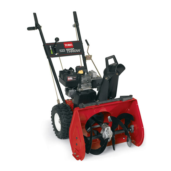
522 Power Throw
Model No. 38605—Serial No. 270000001 and Up
Introduction
Read this information carefully to learn how to operate
and maintain your product properly and to avoid injury
and product damage. You are responsible for operating
the product properly and safely.
You may contact Toro directly at www.Toro.com for
product and accessory information, help finding a
dealer, or to register your product.
Whenever you need service, genuine Toro parts, or
additional information, contact an Authorized Service
Dealer or Toro Customer Service and have the model
and serial numbers of your product ready. Figure 1
identifies the location of the model and serial numbers
on the product. Write the numbers in the space
provided.
Figure 1
1. Model and serial number location
Model No.
Serial No.
© 2009—The Toro® Company
8111 Lyndale Avenue South
Bloomington, MN 55420
®
Snowthrower
This manual identifies potential hazards and has
safety messages identified by the safety alert symbol
(Figure 2), which signals a hazard that may cause serious
injury or death if you do not follow the recommended
precautions.
1. Safety alert symbol
This manual uses 2 words to highlight information.
Important calls attention to special mechanical
information and Note emphasizes general information
worthy of special attention.
Replacement Engine Owner's Manuals may be
ordered through the engine manufacturer.
Register at www.Toro.com.
Form No. 3355-525 Rev E
Operator's Manual
Figure 2
Original Instructions (EN)
Printed in the USA
All Rights Reserved
Advertisement
Table of Contents

Related Manuals for Toro 38605


Summary of Contents for Toro 38605
- Page 1 Whenever you need service, genuine Toro parts, or additional information, contact an Authorized Service Dealer or Toro Customer Service and have the model This manual uses 2 words to highlight information. and serial numbers of your product ready. Figure 1...
-
Page 2: Before Operating
Safety Before Operating Caution: Improper use may result in loss of fingers, hands, or feet. Read and understand the contents of this manual before operating the snowthrower There is a high-speed Become familiar with all controls and know impeller close to the how to stop the engine quickly opening. -
Page 3: Clearing A Clogged Discharge Chute
– Never fill containers inside a vehicle or on a • When cleaning, repairing or inspecting the snow truck or trailer bed with a plastic liner. Always thrower, stop the engine and make certain the place containers on the ground, away from your auger/impeller and all moving parts have stopped. -
Page 4: Maintenance And Storage
Remove the key from the ignition switch The following list contains safety information specific before storing the snow thrower. to Toro products or other safety information that you • Purchase only genuine Toro replacement parts and must know. accessories. -
Page 5: Safety And Instructional Decals
Safety and Instructional Decals Important: Safety and instruction decals are located near areas of potential danger. Replace damaged decals. 53-7670 1. Cutting/dismemberment of foot, auger 112-6621 1. Wheel drive 3. Disengage 5. Read the Operator’s 7. Thrown objects, keep Manual. bystanders a safe distance from the snowthrower. - Page 6 112-6636 1. Forward drive speed settings 2. Speed selector 3. Reverse drive speed setting 1. Warning—hot surface, do not touch Tecumseh Part No. 36501 1. Primer Tecumseh Part No. 35077 1. Key ignition 5. Increasing scale 2. Engage to start the engine 6. Slow 3.
-
Page 7: Installing The Handle
Setup Loose Parts Use the chart below to verify that all parts have been shipped. Procedure Description Qty. Handle Bolts Install the handle. Belleville washers Flange nut Speed selector rod Cotter pin Install the speed selector rod. Flat washer Flange locknut Install the traction rod. -
Page 8: Installing The Speed Selector Rod
3. Thread a flange nut (not the flange locknut) with the flange down onto the traction rod attached to the left side of the handle (Figure 4). Figure 5 1. Axle pin 2. Hole in wheel hub and outer axle hole aligned Note: If you install tire chains (optional), you must install the axle pins through the outer axle holes. -
Page 9: Installing The Traction Rod
2. Move the speed selector lever (Figure 13) on the top of the handgrip and the bottom of the traction control panel to the R (Reverse) position. control lever is 1 to 2 inches (3 to 5 cm) as shown in Figure 7. -
Page 10: Installing The Chute Control Rod
5. Installing the Chute Control Chute control rod assembly (rod and bracket, worm gear, and bracket) Carriage bolt Belleville washer Hex head bolt Locknut Procedure 1. Assemble the chute control bracket and rod to the left side of the handle with the bolt and the locknut as shown in Figure 10. -
Page 11: Filling The Engine With Oil
3. Loosely mount the worm gear and the bracket to the 5. Wipe the dipstick clean with a clean cloth. mounting flange with a bolt, a Belleville washer, and 6. Install the dipstick into the filler neck, then remove it. a locknut as shown in Figure 11. -
Page 12: Product Overview
Product Overview • Traction Control Lever—To engage the traction (wheel drive), press the lever against the left handgrip. To stop the traction, release the lever. • Speed Selector Lever—This control has 4 positions: 3 forward speeds and 1 reverse. To change speeds, move the speed selector lever to the desired position. -
Page 13: Operation
Operation Note: Determine the left and right sides of the machine from the normal operating position. Freewheeling or Using the Self-propel Drive Figure 18 You can operate the snowthrower with the self-propel 1. Spark-plug wire 3. Carburetor heater box feature engaged or disengaged (freewheeling). 2. -
Page 14: Installing The Carburetor Heater Box
Installing the Carburetor Starting the Engine Heater Box 1. Connect the spark plug wire (Figure 20). To install the carburetor heater box, reverse the steps given in Removing the Carburetor Heater Box. Remove the fasteners from their holes before installing the carburetor heater box. - Page 15 Figure 23 5. Insert the ignition key (Figure 24). Figure 26 Important: To prevent damaging the electric starter, run it no more than 10 times at intervals of 5 seconds on, then 5 seconds off. If the engine Figure 24 does not start after this series of attempts, allow the starter to cool for at least 40 minutes before 6.
-
Page 16: Stopping The Engine
Stopping the Engine Operating Tips 1. Engage the auger to remove any remaining snow from inside the housing. 2. Run the engine for a few minutes to dry off any When the snowthrower is in operation, the accumulated moisture. impeller and auger can rotate and cut off or injure hands and feet. -
Page 17: Recommended Maintenance Schedule(S)
Maintenance Note: Determine the left and right sides of the machine from the normal operating position. Recommended Maintenance Schedule(s) Maintenance Service Maintenance Procedure Interval • Inspect and adjust the traction drive belt. After the first hour • Inspect and adjust the auger/impeller drive belt. •... -
Page 18: Adjusting The Skids And Scraper
SG, SH, or SJ. For extremely cold conditions (below 0°F or -18°C), use 0W-30 detergent oil that has the American Petroleum Institute (API) service classification SF, SG, SH, or SJ. Important: Do not overfill the crankcase with oil and run the engine; engine damage will result. -
Page 19: Checking The Auger Gearbox Grease
4. Loosen the flange nuts that secure the selector plate 6. With the drive assembly 1/8 inch (3 mm) from the to the control panel (Figure 29). roll pin, tighten the flange nuts that secure the speed selector plate. 7. Shift the speed selector lever to the R (Reverse) position and back to third gear to check the adjustment. -
Page 20: Lubricating The Snowthrower
Lubricating the Snowthrower • For temperatures between 0°F and 32°F (-18°C to 0°C), use SAE 5W30 or SAE 10. Service Interval: Every 20 hours • For air temperatures below 0°F (-18°C), use Yearly or before storage SAE 0W30. 1. Block up the rear of the snowthrower. Lightly lubricate all moving parts of the snowthrower after every 20 operating hours and at the end of the 2. -
Page 21: Inspecting And Replacing The Spark Plug
Figure 35 1. 0.030 inch (0.76 mm) 5. Install the spark plug by hand and then torque it to 15 ft-lb (20.4 N-m). Note: If you do not have a torque wrench, tighten the plug firmly. Figure 34 Adjusting the Traction Drive Belt Important: Do not excessively oil the Service Interval: After the first hour... - Page 22 Figure 36 1. Flange-head bolt (2) 2. Belt cover 3. Loosen the belt guide (Figure 37). Figure 38 1. Notch in side plate 3. Large traction pulley 2. Spring The spring is under heavy tension and could injure the you or a bystander if you do not carefully remove it.
-
Page 23: Adjusting The Auger/Impeller Drive Belt
Replacing the Auger/Impeller 18. Check the auger/impeller drive linkage and adjust it if necessary. Refer to steps 4 through 7 of Installing Drive Belt the Auger/Impeller Drive Control Linkage in Setup. If the auger/impeller drive belt becomes worn, 19. Install the belt cover. oil-soaked, or otherwise damaged, replace the belt. -
Page 24: Preparing The Snowthrower For Storage
4. Open the fuel shutoff valve and allow the fuel to 11. Pull the recoil starter slowly to distribute the oil on drain out of the fuel tank into the drain pan. the inside of the cylinder. 5. Install the fuel line onto the fuel shutoff valve and 12. -
Page 25: Troubleshooting
5. Unclog the discharge chute. 6. The auger/impeller drive belt is loose 6. Install and/or adjust the auger/impeller or is off the pulley. drive belt; refer to www.Toro.com for servicing information or take the snowthrower to an Authorized Service Dealer. - Page 26 Corrective Action 7. The auger/impeller drive belt is worn 7. Replace the auger/impeller drive belt; or broken. refer to www.Toro.com for servicing information or take the snowthrower to an Authorized Service Dealer. Discharge chute either does not lock into 1. The discharge chute latch is not 1.
- Page 27 Notes:...
- Page 28 (Dealer) to obtain guarantee policies for your country, province, or state. If for any reason you are dissatised with your Distributor’s service or have difculty obtaining guarantee information, contact the Toro importer. If all other remedies fail, you may contact us at Toro Warranty Company.