
Related Manuals for Toro 30739


Summary of Contents for Toro 30739
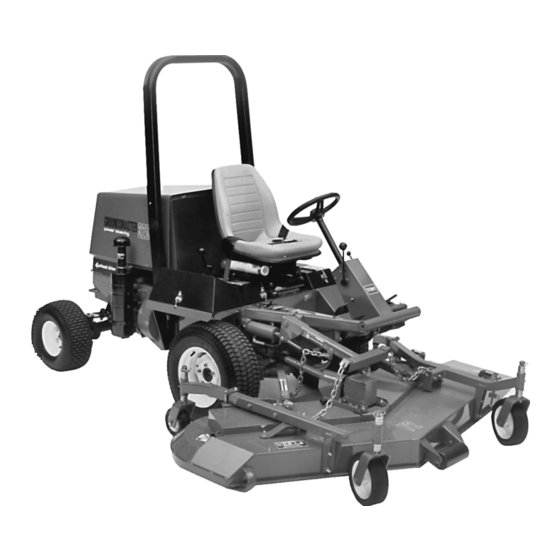
- Page 1 FORM NO. 3318-411 GB Rev A OPERATOR’S MODEL NO. 30739—60001 & UP MANUAL MODEL NO. 30741—60001 & UP ® GROUNDSMASTER ® 325-D TRACTION UNITS © The TORO Company, 1996...
-
Page 2: Table Of Contents
Use model and serial number in all correspondence and when ordering parts. To order replacement parts from an authorized TORO Distributor, supply the following information: Model and serial numbers of the machine. -
Page 3: Safety
Safety Training ment is to be used and remove all objects which may be thrown by the machine. Read the instructions carefully. Be familiar with the controls and the proper use of the equip- WARNING—Petrol is highly flammable. ment. • Store fuel in containers specifically designed for this purpose. -
Page 4: Maintenance And Storage
4. Do not use on slopes of more than: sonal injury. • Never mow side hills over 5° 12. Before leaving the operator's position: • Never mow uphill over 10° • disengage the power take-off and lower the • Never mow downhill over 15° attachments;... - Page 5 Sound & Vibration Levels enclosure. To reduce the fire hazard, keep the engine, Sound Levels silencer, battery compartment and petrol storage area free of grass, leaves, or excessive grease. This unit has an equivalent continuous A-weighted sound pressure at the operator ear of: 89 dB(A), based on mea- Check the grass catcher frequently for wear or surements of identical machines per 84/538/EEC.
- Page 6 Symbol Glossary Caustic liquids, Poisonous Electrical shock, High pressure High pressure High pressure Crushing of Crushing of chemical burns to fumes or toxic electrocution fluid, injection spray, erosion of spray, erosion of fingers or hand, toes or foot, force fingers or hand gases, asphyxiation into body flesh...
- Page 7 Consult technical Fasten seat Safety alert Outline safety Read operator’s Fire, open light Eye protection manual for proper belts triangle alert symbol manual and smoking must be worn service prohibited procedures Head protection Hearing Caution, toxic First aid Flush with water Engine Transmission Hydraulic system must be worn...
- Page 8 n/min Engine start Engine stop Engine failure/ Engine rotational Choke Primer (start aid) Electrical preheat Transmission malfunction speed/frequency (low temperature start aid) N H L F Transmission Transmission Transmission Clutch Neutral High Forward oil pressure oil temperature failure/malfunction Reverse Hydraulic oil Hydraulic oil Second gear Hydraulic oil...
-
Page 9: Specifications
SAE 10W-40 SF/CC or CD engine oil. The 25-micron hydraulic oil filter is a screw-on replaceable type. For Air Cleaner: Heavy-duty, remote mounted. replacement filters, order Toro part number 67-8110. Muffler: Volume equal to approximately six times Ground Speed: Speed is infinitely variable from 0 to engine displacement for excellent silencing. - Page 10 engine off when the traction pedal is engaged with no operator on the seat. Seat Switch—Shuts the engine off if the operator leaves the seat without disengaging the PTO and/or the traction pedal. The engine will not start if the PTO or the traction pedal is engaged.
-
Page 11: Before Operating
Before Operating CHECK THE CRANKCASE OIL The engine is shipped with 3.7 quarts (3.5 L) of oil in the crankcase; however, the level of the oil must be checked before and after the engine is first started. Position the machine on a level surface. Disengage the hood latch and open the hood. - Page 12 low temperatures (wax appearance, which may plug filters). Number 2-D diesel fuel above 20° F (–7° C) will contribute toward longer life of the pump components. Do not use furnace oil. Furnace oils usually contain heavy cracked distillates which are not suitable for diesel engines. Store fuel outside of buildings in a convenient location.
-
Page 13: Check The Cooling System
If possible, fill the Groundsmaster 325-D fuel tank at the end of each day’s operation. This will prevent possible build-up of condensation inside the fuel tank and possible engine damage. Let the engine thoroughly cool down before refueling. Tip the seat forward and prop it with the support rod so it cannot fall accidentally. - Page 14 Expected Recommended Ambient Viscosity Temperature and Type (Extreme) over 90 F SAE 30, Type SF/CC or CD engine oil. (Normal) 40-1 00 F SAE 10W-30 or 10W- 40, Type SF/CC or CD engine oil. (Cool - Spring/Fall) SAE 5W-30, Type 30-50 F SF/CC or CD engine oil.
-
Page 15: Controls
Controls Traction Pedal (Fig. 5)—The traction pedal moves the machine forward and backward. Using the heel and toe of the right foot, depress the top of the pedal to move forward and the bottom of the pedal to move backward. Ground speed depends on how far you press the pedal. - Page 16 must be evenly adjusted. Lift Lever (Fig. 6)—The hydraulic lift lever has three posi- tions: FLOAT, TRANSPORT and RAISE. To lower the imple- ment to the ground, move the lift lever forward into notch, which is the FLOAT position. To raise the implement, pull the lift lever backward to the RAISE position.
- Page 17 contrast, the alternator is not charging the battery when the nee- dle points to the (-) negative side of ammeter. If this happens, repair the charging system to prevent discharge of the battery. Temperature Switch/Gauge and Reset Button (Fig. 7)—The temperature switch/gauge registers the temperature of the coolant in the cooling system.
- Page 18 Engine Stop Lever (Fig. 10)—Located on the lower right side of the engine inboard of the air cleaner assembly. Provided as a means to stop the fuel flow, thereby stopping the engine, if an electrical malfunction should occur. Use only for emergencies. Seat Adjusting Levers (Fig.
-
Page 19: Operating
Operating STARTING AND STOPPING THE ENGINE IMPORTANT: The fuel system must be bled if any of the following situations have occurred: A. Initial start-up of a new machine. B. The engine has stopped running because of lack of fuel. C. Maintenance has been done on the fuel system compo- nents;... -
Page 20: Bleeding The Fuel System
NOTE: Do not exceed 1 minute of continuous use or the glow plug prematurely burn out. When the engine is started for the first time, or overhaul of the engine, transmission or axle, operate the machine in forward and reverse for one to two minutes. Also operate the lift lever and the PTO lever to assure proper operation of all parts. - Page 21 CHECKING THE INTERLOCK SWITCHES The machine has interlock switches in the electrical system. These switches are designed to stop the engine when you get off the seat while either the PTO lever is engaged or the traction pedal is depressed. However, you may get off the seat while the engine is running.
- Page 22 PUSHING OR TOWING THE TRACTION UNIT In an emergency, the traction unit can be pushed or towed for a very short distance. However, Toro does not recommend this as standard procedure. IMPORTANT: Do not push or tow the traction unit faster than 2 to 3 mph (3 to 4.8 km/hr) because the transmission...
- Page 23 decreases, and depress the pedal slowly as rpm increases. By comparison, when driving from one work area to another—with no load and cutting unit raised—have the throttle in the FAST position and depress the traction pedal slowly but fully to attain maximum ground speed.
- Page 24 GREASING BEARINGS, BUSHINGS, GEAR BOX AND BRAKE CABLES The traction unit must be lubricated regularly. If the machine is operated under normal conditions, lubricate all bearings and bushings after every 50 hours of operation. The traction unit bearings and bushings that must be lubricated are: the PTO shaft and yokes (Fig.
-
Page 25: Maintenance Schedule
Figure 21 Figure 22 Maintenance Schedule Hour Service Interval Meter Check The interlock System Daily Check Engine Oil Level Daily Check The transmission Oil Level Daily Check The radiator and Coolant (more often when conditions are dirty) Daily Drain The fuel Filter/Water Separator Daily Replace The hydraulic Oil Filter (initial) Tighten Front Wheel Nuts (Initial) - Page 26 Figure 23 Figure 26 Thumbscrew Dipstick Dust Cup Dipstick tube Baffle Keep oil level between notches Engine oil filter Figure 24 Wing nut with gasket Figure 27 Filter element Fuel filter/water separator Air cleaner body Drain plug Figure 25 Figure 28 Oil drain plug Fuel pump assembly Drive coupling assembly...
- Page 27 Figure 29 Figure 32 Filter Dipstick Magnet Groove Figure 33 Traction unit model and serial number Figure 30 Hydraulic oil filter Filter 31 Drain plug...
- Page 28 Clean the battery, terminals and posts with a wire brush and baking soda solution. Coat the cable terminals and the battery posts with Grafo 112 X skin-over grease (Toro Part Number 505-47), or petroleum jelly to prevent corrosion.