
Related Manuals for Lennox DC 60

Summary of Contents for Lennox DC 60
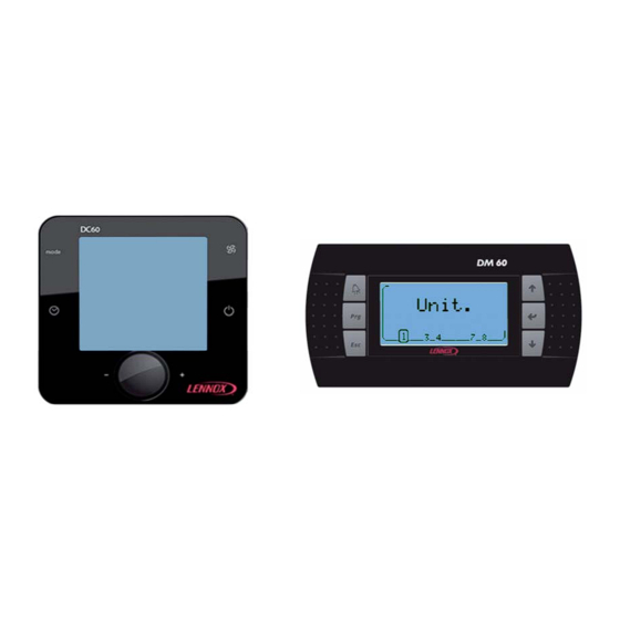
- Page 1 User manual DC 60 DM 60 DC 60 & DM 60 displays DC60-DM60_ROOFTOP-IOM-1310-E lennoxemeia.com...
-
Page 3: Table Of Contents
Summaries Display ‘DC60’ Introduction 4 Temperature measurement 4 Quick Action 5 Presentation 7 DC60 set in ‘Light’ mode DC60 set in ‘Full’ mode Setting Value Activation level 2 Display ‘DM60’ Quick Action 13 Functionality of the DM60 16 Organizational screens Alarm List by Code 24 DC60, Installation Connection 27... -
Page 4: Display 'Dc60
1.2 Temperature measurement All Lennox Unit comes with a temperature sensor; it must be placed in the conditioned area. But if the 'DC60' is placed in the area conditioned by the Unit, it is possible, in this case, to use the temperature measurement of the 'DC60'. -
Page 5: Quick Action
1.3 Quick Action How to See the Operation of the Unit 4 ? 1.3.1 Only if several units are connected to the DC60. Turn the knob to have the text ‘Unit’. Press the knob to switch in 'Set' mode. Turn the knob to select number 4. Press the knob to confirm your choice How to Start all Units connected at this DC60 ? 1.3.2... - Page 6 How to Start Unit 4 ? 1.3.3 Only if several units are connected to the DC60. Select the Unit 4 (see: How to See the Operation of the Unit 4 ?) Turn the knob to have the text ‘I-O’. Press the knob to switch in 'Set' mode. Turn the knob to select number 1 (1 for ‘On’, 0 for ‘Off’).
- Page 7 How to Modify the Value of the Current Setpoint Temperature ? 1.3.5 Turn the knob to have the text ‘Set’. Press the knob to switch in 'Set' mode. Turn the knob to change the value. Press the knob to confirm your choice DC60-DM60-ROOFTOP-IOM-1310-E - 5 -...
-
Page 8: Presentation
1.4 Presentation Showing 1.4.1 Buttons 1.4.2 DC60-DM60-ROOFTOP-IOM-1310-E - 6 -... -
Page 9: Use
1.5 Use Control operating mode. 1.5.1 Only for Flatair and Aqualean ranges. Press until the desired operating mode is displayed. Heating mode Cooling mode Automatic mode Fan Speed Management. 1.5.2 Only for Flatair and Aqualean ranges. Press to select the desired speed (min, med, max) or automatic (Auto). Minimum speed Median speed Maximum speed... -
Page 10: Dc60 Set In 'Light' Mode
Setting time 1.5.4 At initialization of the 'DC60', the Climatic™60 are synchronized time and day of week with the clock 'DC60'. To view the clock, briefly, press the button To set the clock press the button a few seconds The hour value, flashes. Turn the knob to adjust the desired value. -
Page 11: Dc60 Set In 'Full' Mode
Alarms code 1.6.3 This item allows you to view the code of different active alarms on the Unit. If the Unit isn't in alarm, this item is to 0. Indoor (Room) temperature 1.6.4 This item indicates the measured air temperature in the room conditioning. The room temperature isn't available if the Climatic™60 is configured to supply control. -
Page 12: Setting Value
Alarms code 1.7.5 This item allows you to view the code of different active alarms on the Unit. If the Unit isn't in alarm, this item is to 0. By this item it's possible to reset the alarm activated. To do this set the value of the item to the value 0. Outdoor temperature 1.7.6 This item indicates the measure temperature of the air outside. -
Page 13: Activation Level
1.9 Activation level 2 (2 buttons on the right simultaneously) Simultaneously press the keys After some seconds the text appears and the value '000' flashes. Turn the knob to change the value to select the number 066. Then validate the code by pressing the knob. If the code is wrong access the setup menu is not possible and the 'DC60' returns to the previous display. -
Page 14: Display 'Dm60
It allows an overview of the operation of the Unit and allows access to some parameters. The 'DM60' is designed to be remotely connected of the Unit. The 'DM60' can be connected to several Lennox Units, Between 1 and 8 units 2.1 Quick Action How to See the Operation of the Unit 4 ? 2.1.1... - Page 15 How to Start Unit ? 2.1.2 Press ‘Prg’ to activate the setup menu If necessary, press several times ‘Up’ or ‘Down’ to blacken the icon Press ‘Enter’ to confirm your choice Press ‘Up’ or ‘Down’ to change the state ‘Off’ to ‘On’ Press ‘Enter’...
- Page 16 How to See the Value of the Current Setpoint Temperature ? 2.1.3 Press ‘Prg’ to activate the setup menu If necessary, press several times ‘Up’ or ‘Down’ to blacken the icon The value displayed is the temperature setpoint. Press ‘Esc’ to return to the main screen How to Modify the Value of the Current Setpoint Temperature ? 2.1.4 Press ‘Prg’...
-
Page 17: Functionality Of The Dm60
2.2 Functionality of the DM60 Selection of Unit 2.2.1 A DM60 can be connected to 8 units on the pLan bus. Screens DM60 connected, alternatively, to one of BM60. The next screen allows selection of the unit to display: Each of the 8 Unit is represented by a number. The Unit selected is indicated by its number which is framed. - Page 18 Mode Day I Mode Day II Bottom left: If the unit is in alarm, this symbol is displayed. Button 'Alarm': Go to Alarm list. Button 'Prg': Go to Setup menus of the unit. Button 'Esc': Return to the choice of Unit selected. Button 'Up Arrow': Go to another display of the Unit operation.
- Page 19 Alarm list 2.2.4 History used to store the last 99 alarms occurred on the unit. Each alarm is stored on the date and time the fault occurred. An active alarm is signified by the symbol 'Bell'. An alarm not active is signified by the symbol '.'. Each alarm is signified by a 3 digit code To have the text of fault code, position the cursor on the desired line, by using the 'Up Arrow' or 'Down Arrow' and then confirm by pressing 'Enter'...
- Page 20 Button 'Up Arrow': Increases the set-point value. Button 'Enter': Valid the changes then return to Setup menus of the unit. Button 'Down Arrow': Decreases the set-point value. Setting; On/Off Unit 2.2.7 View/edit, status of Off/On of the unit. Button 'Alarm': Go to Alarm list. Button 'Esc': Return to Setup menus of the unit.
- Page 21 Setup menus Plus 2.2.10 Access to the setup menus is protected by a password. The password must be entered digit by digit. If the password is correct, the lock opens, and the selection of the choice of function is active. Button 'Alarm': Go to Alarm list.
- Page 22 Button 'Up Arrow': Change the schedule mode or Increases the set-point value. Button 'Enter': Valid the changes and puts you to the next field. Button 'Down Arrow': Change the schedule mode or Decreases the set-point value. Setting; Reset Alarms 2.2.13 View/edit, reset of alarm and safety.
-
Page 23: Organizational Screens
2.3 Organizational screens Selection of Unit 2.3.1 Unit Operation 2.3.2 Alarm list 2.3.3 DC60-DM60-ROOFTOP-IOM-1310-E - 21 -... - Page 24 Setup menus 2.3.4 DC60-DM60-ROOFTOP-IOM-1310-E - 22 -...
-
Page 25: Alarm List By Code
Alarm List by Code Code Alarm Blower, Flow Switch Cut Off Water Condenser, Flow Switch Cut Off Water Condenser, Flow Delta-T Blower, Filters, Dirty Blower, Filters, Missing Unit Power Supply Electrical Heaters, Overheating Fresh Air, Electrical Heater, Overheating Hot Water, Risk Of Frosting Gas Burner 1 Gas Burner 2 Gas Burner, Overheating... - Page 26 Code Alarm Supply Temperature, Probe Water Condenser, Inlet, Probe Water Condenser, Outlet, Probe Return Temperature, Probe Air Quality, Sensor Blower Pressure, Sensor Blower, Fan Blower, Inverter Exhaust, Fan Exhaust, Inverter Fire / Smoke, Detected EVD, Communication Bus Circuit 1, Condenser Fan Circuit 1, Condenser Fan, Inverter Circuit 1, Leak Refrigerant, Detected Circuit 1, Compressor, Electrical...
- Page 27 Code Alarm Circuit 2, Low Condensing Temperature Circuit 2, Low Superheat Circuit 2, High Superheat Circuit 2, Low Subcooling Circuit 2, High Subcooling Circuit 2, MOP, Maximum Operating Pressure Circuit 2, LOP, Low Operating Pressure Circuit 2, High Condensing Temperature Circuit 2, Expansion Valve, Motor Circuit 2, High Pressure, Sensor Circuit 2, Low Pressure, Sensor...
-
Page 28: Dc60, Installation
4.1.1 An error connecting to the display immediately causes the deterioration of this one or BM60. Any wiring modification on the CLIMATIC 60 must be done by Lennox technician or employees having valid electrical qualification and authorization. DC60-DM60-ROOFTOP-IOM-1310-E - 26 -... - Page 29 The power of the 'DC60' can be 24Vac (+10…-15%) 50/60Hz or 24Vdc (22…35Vdc), maximum current of 2VA. Lennox recommends a 24Vac supply (provided by Unit) for installation of the display less within 30 meters of Unit. For connection of the display of over 30 meters, a power supply, close to the display, 24Vac must be provided by the installer.
-
Page 30: Ferrites Protection Of Displays
4.3 Temperature Sensor All Lennox Unit comes with a temperature sensor; it must be placed in the conditioned area. But if the 'DC60' is placed in the area conditioned by the Unit, it is possible, in this case, to use the temperature measurement of the 'DC60'. -
Page 31: Initialization
Choice of Parameters 4.4.2 By rotating of the knob you can view and modify the following parameters: Address 'DC60' on the communication bus (Always set to value 31) Communication speed (always set to value 2) Backlight mode Intensity of the backlight Probe calibration Screen contrast Disabling 'Bip' keys... -
Page 32: 'Dm60', Installation
5.1.1 An error connecting to the display immediately causes the deterioration of this one or BM60. Any wiring modification on the CLIMATIC 60 must be done by Lennox technician or employees having valid electrical qualification and authorization. Power supply 5.1.2 The 'DM60' is powered by the BM60. -
Page 33: Connection On The Splitter Dt50
If J14 and J15 are set differently, the dispatcher DT50 DOESN'T WORK and therefore displays connected don't work 5.3 Ferrites Protection of Displays To prevent radio interference that may cause miscommunication or destruction of elements on the screen, you need to equip each end of the cable a ferrite (supplied by Lennox). DC60-DM60-ROOFTOP-IOM-1310-E - 31 -... -
Page 34: Configuration
5.4 Configuration Brightness / Contrast 5.4.1 The display is equipped with a contrast, but it can be adjusted manually. For manual adjustment of contrast, simultaneously press the keys 'Alarm' and 'Prg' and press buttons 'Arrow' or 'Down Arrow' to increase or decrease the contrast. -
Page 35: Dc60-Dm60 Communication Master/Slaves
- For a length of 0 to 300m: AWG22 (0.34 mm ²), a twisted pair shielded. - For a length of 0 to 500m: LiYCY-P (0.34 mm ²), a pair overall shield. The cable length should not exceed 500m. For better protection of electromagnetic disturbances Lennox recommends the installation of cable LiYCY-P Setting 6.1.2 Each Climatic™... - Page 36 PORTUGAL +33 4 72 23 20 00 +351 229 066 050 Due to Lennox’s ongoing commitment to quality, the specifi cations, ratings and dimensions are subject to change without notice and without incurring liability. Improper installation, adjustment, alteration, service or maintenance can cause property damage or personal injury.
Need help?
Do you have a question about the DC 60 and is the answer not in the manual?
Questions and answers