Table of Contents
Advertisement
Quick Links
Advertisement
Table of Contents

Related Manuals for GRAUPNER mx-16 HOTT


Summary of Contents for GRAUPNER mx-16 HOTT
- Page 1 33116.mx-16 HoTT.3.en mx-16 Programming Manual...
-
Page 2: Table Of Contents
Contents General Information Telemetry data displays ......... 30 “Transmitter control settings” On-screen warnings ..........36 Fixed-wing model aircraft ........94 Contents ................ 2 On-screen function fields........36 Model helicopter ............ 96 Environmental protection notes ........3 Position indicator of rotary controls CTRL 7 + 8 ..37 Throttle limit function ........ -
Page 3: Environmental Protection Notes
The sole purpose of this manual is to provide informa- tion; it is subject to amendment without prior notification. Graupner accepts no responsibility or liability for errors or inaccuracies which may occur in the information section of this manual. -
Page 4: Safety Notes
Graupner connectors of the same design with pectedly, with the result that parts may fly off at great cabling of all kinds, etc.. - Page 5 any other installed equipment in the model, but in an Ensure that no metal parts are able to rub against each from other transmitters and any interference, and may easily accessible position. Under no circumstances al- other, e. g. when controls are operated, when parts respond.
- Page 6 Keep the receiving system an adequate distance away tant to avoid short-circuits. Do this by first connecting the Refer to the main Graupner FS catalogue or the Internet from the ignition system. banana plugs on the charge lead to the charger, taking website at www.graupner.de for more information on...
- Page 7 Liability exclusion / Compensation effects on the system’s electrical characteristics and It is not possible for Graupner to ensure that the user radiation pattern. observes the installation and operation instructions, and •...
-
Page 8: Safety Notes And Handling Instructions Relating To Nickel-Metal-Hydride Rechargeable Batteries
Safety notes and handling instructions relating to Nickel-Metal-Hydride rechargeable batteries As with all sophisticated technical products, it is vitally charge. Never exceed the maximum fast-charge cur- with every charge / discharge process. Stored batteries important that you observe the following safety notes rent specified for the cell type in use. -
Page 9: Disposal Of Exhausted Dry And Rechargeable Batt
… 20 mV per cell, and can therefore be used equally tion points, Graupner retail outlets, and any other shop well for NiCd batteries and for NiMH batteries. If you where dry and rechargeable batteries of the same type are unsure, refer to the operating instructions or are sold. -
Page 10: Foreword
HoTT - a radio control system of ules in order to implement complex coupled functions, equates to an enormous gain in safety, especially at the latest generation. -
Page 11: Description Of Radio Control Set
Computer System Eight-channel radio control set with Graupner|SJ HoTT 2.4 GHz technology (Hopping Telemetry Transmission) • Micro-computer radio control system exploiting the latest Graupner|SJ HoTT 2.4 GHz technology • Bi-directional communication between transmitter and receiver • Five different languages English, French, German, Italian and Spanish •... - Page 12 Computer System Eight-channel radio control set with Graupner|SJ HoTT 2.4 GHz technology (Hopping Telemetry Transmission) • Seven switches (two three-way switches, three two- linkages (1 servo, 2 servo, 3sv(2roll), 3sv(140°), servos only) way switches and two momentary switches), plus 3sv(2nick (pitch-axis)), 4 SV (90°))
-
Page 13: Technical Specifications
2498.4FBEC 4NH-2000 RX RTU, flat-pack de. Alternatively you can enquire at your local model listed here, please refer to the main Graupner FS catalogue, or our 33800 HoTT transmitter aerial shop, where the staff will be pleased to advise you. -
Page 14: Operating Notes
NiMH damage to the internal battery socket. cells. The mx-16 HoTT transmitter is fitted as standard with a high-capacity rechargeable 4NH-2000 RX RTU NiMH As an approximate guideline a discharged battery First connect the banana plugs on the charge lead battery (Order No. - Page 15 transmitter, in the direction of the circuit board. (The bat- disconnected; for example, when the transmitter battery tery connector is protected against reversed polarity by is replaced. two chamfered edges; see illustration). Finally place the battery in the compartment, and close the cover.
-
Page 16: Receiver Power Supply
This applies in particular if you are Note: using an automatic charger designed for NiCd batter- Please refer to the main Graupner FS catalogue or visit ies to recharge the standard NiMH battery. the Internet site at www.graupner.de for full details of •... -
Page 17: Adjusting The Stick Length
Graupner Service Centre to carry out the work for you. Hold the bottom half of the knurled grip firmly, and C A U T I O N... -
Page 18: Changing The Stick Mode
Operating Notes Converting the dual-axis stick units Self-centring action Either or both sticks can be converted from self-neutral- Folding aerial ising to non self-neutralising action: start by opening the transmitter as described on the previous page. If you wish to change the standard stick unit arrange- ment, start by locating the screw on the left-hand stick unit shown circled in white in the photo below. - Page 19 Brake spring and ratchet Stick centring force You can alter the braking force of the stick by adjusting The centring force of the sticks is also variable to suit the outer of the two screws circled in white in the next your preference.
-
Page 20: Description Of Transmitter
You will find a strap lug mounted in the centre of the Aerial with folding / rotating base front face of the mx-16 HoTT transmitter, as shown in Neckstrap lug the drawing on the right. This lug is positioned in such a... -
Page 21: Rear Of Transmitter
For connecting the optional Smart-Box, Order No. 33700. Transmitter battery For more details about the Smart-Box please refer to the charge socket main Graupner FS catalogue, or refer to that product on Battery compartment cover the Internet at www.graupner.de. Case screw... -
Page 22: Dsc (Direct Servo Control)
Direct Servo Control Card slot micro-SD and micro-SDHC The original function of this socket was for “Direct Servo When you switch off the mx-16 HoTT transmitter and PUPIL stop 0:00 Control”, and that’s why the abbreviation is still in use. - Page 23 Corresponding updates and information can be found commences - provided that a suitable memory card in the Download area of www.graupner.de under the is in the card slot, and a telemetry connection to the product concerned.
-
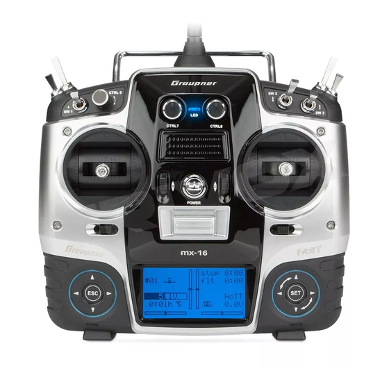
Page 24: Screen And Keypad
Screen and keypad Visual display of the trim lever positions; alternatively - if rota- ry controls CTRL 7 … 9 are operated - display of the current settings of these two controls Model type display Model name See page 36 for possible warnings (fixed-wing / helicopter) Stopwatch in min:sec Model memory 1 …... -
Page 25: Operating The "Data Terminal
Operating the “Data Terminal” Input buttons ESC and SET Short-Cuts symbols On-screen telemetry symbols Buttons to the right of the screen You can call up particular menus or options directly us- ing the following button combinations: The active model memory has not yet been •... -
Page 26: Hidden Mode
Language selection and screen contrast The “HIDDEN MODE” (VERSTECKTER MODUS) menu or using the SD card supplied in the set, as described DATEILISTE of the mx-16 HoTT transmitter can be accessed from in the following section. If you have not already done VOICE2_ENGLISH.VDF VOICE2_FRANCE.VDF... -
Page 27: Changing The Screen Language
“VoiceFile” folder • Italian by inserting the SD card in a PC or laptop. • Spanish Corresponding updates and further information can be found at www.graupner.de on the mx-16 HoTT pro- duct page under Download. Description of transmitter... -
Page 28: Stick Calibration
… then there is no memory card in the card slot, or to the “Servo display” menu with, for example, a simul- the card cannot be read. taneous brief press of the buttons of the left-hand Boot Download ... - Page 29 transmitter’s screen display should look like this: STICK CALIBRATION STICK CALIBRATION –100 % Move the “left” flashing arrow marker to the left-hand Now repeat the calibration procedure for the right-hand end-point using the right-hand stick - again without end-point of the right-hand stick. Repeat the procedure If this checking procedure shows a result of up to four exerting pressure …...
-
Page 30: Telemetry Data Displays
Appendix, or refer to the product on the Internet at www. activated in the “SELECT SENSOR” sub-menu of the RX-VOLT Actual receiver operating voltage in graupner.de. “Telemetry” menu by briefly pressing one of the arrow Volts buttons of the left or right-hand touch-key …... - Page 31 / voltage sensor, Order information on these modules please see the Appendix, No. 33612 or 33613, connected to the “T(EMP)2” socket or refer to the product on the Internet at www.graupner. 0.0A of the General Engine module (Order No. 33610) or the 0mAh General Air module (Order No.
- Page 32 0.0A Appendix, or refer to the product on the Internet at www. This display visualises the data for altitude in m relative graupner.de. 0mAh to the location or launch point, and the actual climb / Depending on the sensors connected to the modules,...
- Page 33 SENSOR 1 to the location or launch point, and the actual climb / The pre-set altitude limit below the sink rate in m/s, generated by the integral vario in the launch point; below this altitude the SENSOR Electric Air module (Order No. 33620). transmitter emits audible warning 0.0V signals...
- Page 34 Vario RXSQ 0.0m/1s 0m/3s 0°00.0000 0°00.0000 This display visualises the data delivered by a GPS module with integral vario, Order No. 33600, connected This display visualises the data for altitude in m relative to the receiver. to the location or launch point, and the actual climb / In addition to the model’s current positional data and sink rate in m/s, generated by the integral vario in the speed, shown in the centre of the screen, the display...
- Page 35 For your notes...
-
Page 36: On-Screen Warnings
On-screen warnings On-screen function fields SEL, STO, SYM, ASY, Warnings The bottom line of the screen displays function fields No connection between which vary according to the menu selected. student “Binding not present” Teacher and Pupil transmitters signal No receiver is bound to the BIND N/A currently active model mem- No SD or SDHC memory card... -
Page 37: Position Indicator Of Rotary Controls Ctrl 7 + 8
CTRL 7 + 8 on the centre console, a small symbol ap- the touch-keys, and with them access to all the set-up pears to the right of the two vertical position indicators: options, from the base display of the mx-16 HoTT transmitter by touching the buttons for about two seconds. -
Page 38: Using The Transmitter For The First Time
Using the transmitter for the first time Preliminary notes regarding the mx-16 HoTT transmitter For more information please visit our Internet site at www.graupner.de Preliminary notes indicator appears instead of the “x” at the base of the RF ON/OFF? symbolic aerial, for example... -
Page 39: Downloading A Firmware Package
Note: that the transmitter aerial is an adequate distance This takes you to the home page of the Graupner com- Once you have registered your transmitter at https:// from the receiver aerials. If the transmitter aeri- pany website, where you will find an input field at top www.graupner.de/en/service/product_registration you... - Page 40 “Restoring the transmitter firmware” on page 43. “HoTT_Software_VX.zip”. This compressed file contains all the files required to update the transmitter, HoTT Updating the mx-16 HoTT software receiver, sensors, etc. To update the transmitter software you only need the Please note: at the time of revising this manual the USB lead supplied as standard with the USB interface, current version of the program package is version “4”...
- Page 41 4. Updating the mx-16 HoTT transmitter software transmitter battery before you carry out any up- window, i.e. the port to which the USB interface is date. For safety’s sake recharge it and back up connected. You can recognise this by the name “Sil- Start the program “Firmware_Upgrade_grStudio_Ver-...
- Page 42 Note: At any time you can call up an explanation of any step in the form of Quick-Info by positioning the mouse pointer over a number. If you have not already done so, connect your trans- mitter to the PC or laptop at this point. Now click At this point the actual update process begins, and a on the button marked “File Browse”...
-
Page 43: Restoring The Transmitter Firmware
Now move to the “Controller Menu” and select the mitter screen switches itself on with the start display “Emergency” entry under the heading “Transmitter”: “mx-16 HoTT”, and the current firmware version is shown on the screen. Finally click on “OK”. Switch the transmitter off, and disconnect the USB lead from the transmitter and the PC or laptop. -
Page 44: Using The Receiver For The First Time
BEC* system in parallel with a separate receiver bat- tery, in most cases (depending on the speed control- The mx-16 HoTT radio control set includes a GR-16 Servo connections and polarity ler) the positive terminal (red wire) must be removed 2.4 GHz bi-directional receiver which is suitable for con-... - Page 45 Please note the following: Resetting the receiver resets ALL the settings stored in the receiver to the default settings, with the exception of the binding information! If you carry out a RESET by mistake, this means that you will have to restore all the receiver settings entered using the Telemetry menu.
-
Page 46: Firmware-Update Of The Receiver
39. be found in the Download area for the corresponding Connecting the receiver to the PC product at www.graupner.de. Connect the USB interface, Order No. 7168.6 to the receiver socket marked “- + T” using the adapter lead, Note: Order No. - Page 47 dialogue which now appears; the file suffix will be lease the button at this point. The actual firmware “bin”. update process now starts automatically: “11, Start Firmware upgrade…”. In the case of the zip file “HoTT_Software_VX” which you have already downloaded and unpacked, this If the device is not detected, a pop-up window ap- will usually be found in the folder whose name starts pears with the message “Target device ID not found”.
- Page 48 reached, switch the receiver power supply off and re- transmission is active: about two or three seconds af- peat the update procedure, i.e. carry out each of the ter this the green LED of the bound receiver will glow steps described above once more. constantly.
- Page 49 For your notes...
-
Page 50: Backing Up Receiver Settings
Backing up receiver settings The “Receiver Setup” segment of the program The connector system is polarised: note the small port number at the entry “Silicon Labs CP210x USB “Firmware_Upgrade_grStudio” can be used to save all chamfers on the edges. Do not use force under any to UART Bridge”. - Page 51 the Download area for the mx-16 on the Graup- the process is complete, this message appears: ner website. • A separate manual for the whole “Firmware_Up- grade_grStudio_Ver-X.X” program package is in preparation, and will be updated constantly as soon as new options are available. Click on “OK”...
-
Page 52: Installation Notes
The sequence in which the servos are connected to the Regardless of which Graupner receiving system you are model: receiver is dictated by the model type. Please see the using, the procedure is always the same: Wrap the receiver in foam rubber at least 6 mm thick. -
Page 53: Receiving System Power Supply
Volt of a two-cell LiFe pack presents no problems to ner/JR DS-281, can draw currents of up to 0.75 Ampere Y-lead, PRX stabilised Graupner|SJ HoTT receivers, nor to those servos, speed Order No. 3936.11 receiver power supply, when stalled (mechanically obstructed). Just four servos Order No. - Page 54 Nanophosphate® types. The comparatively high nominal voltage of 7.4 Volt of a two-cell LiPo pack presents no problems to Graupner|SJ HoTT receivers, nor to those servos, speed control- lers, gyros, etc. which are expressly approved for use at these higher voltages.
- Page 55 For your notes...
-
Page 56: Definition Of Terms
Definition of terms Control functions, transmitter controls, function inputs, control channels, mixers, switches, control switches To make it easier for you to understand the mx-16 • The switches SW 4/5 and 6/7, and CTRL 9 and 10 affect multiple servos at the branching point of the mixer HoTT manual, the following section contains definitions input, or alternatively to allow several control functions •... -
Page 57: Switch And Transmitter Control Assignment
The mx-16 and assign the switch again, this time with the switch For both model types the mx-16 HoTT transmitter’s HoTT allows you to assign several functions to a single direction you prefer. -
Page 58: Digital Trims
Digital trims Description of function, and Ch 1 cut-off trim Digital trims with visual and audible indicators 1. Fixed-wing models 2. Model helicopters The Ch 1 trim features a special cut-off trim which is In helicopter mode the Ch 1 trim has another feature in Both the dual-axis stick units are fitted with digital trim designed for glowplug motors: you initially use the trim addition to “cut-off trim”, as described under “Fixed-wing... - Page 59 For your notes...
-
Page 60: Fixed-Wing Model Aircraft
Fixed-wing model aircraft This program provides convenient support for normal tail, you need to select the tail type “V-tail” in the “Base “Dual Rate” and “Exponential” can be programmed model aircraft with up to two aileron servos and two flap settings”... -
Page 61: Receiver Socket Sequence
Receiver socket assignment for models with up to two ailerons and two flaps, plus “normal” tail type, V-tail, Installation notes and two elevator servos (3 + 8) The servos MUST be connected to the receiver outputs in the following order: Outputs not required are simply left vacant. -
Page 62: Servo With Incorrect Direction Of Rotation
Receiver socket assignment for models of the “Delta / Flying wing” type, with up to two flaps As there are several possible combinations of servo orientation and control surface linkage, you may find that the direction of rotation of one or more servos is incor- rect. - Page 63 For your notes...
-
Page 64: Model Helicopters
The helicopter program of the mx-16 HoTT can cope the “Helicopter mixers” menu provides five-point curves the motor in any flight phase. By default the proportional with all current model helicopters equipped with 1 …... -
Page 65: Receiver Socket Sequence
Note for modellers upgrading from earlier Graupner menu described on page 82 / 83. Installation notes systems: All menus which are relevant to model helicopters are The servos MUST be connected to the receiver Compared with the previous receiver channel sequence, marked with a “helicopter”... -
Page 66: Program Descriptions Setting Up A New Model Memory
Detailed description of programming Reserving a new memory If you have already read through the manual to this select model => point, you will undoubtedly have made your first attempt free => clear model at programming the system already. Even so, it is impor- free ... -
Page 67: Fail Safe
button of the right-hand touch-key briefly in confirmation. to pages 80 and 88. • If the battery voltage is too low, the software prevents This initialises the selected model type for the model you switching model memories in the interests of •... - Page 68 position of the throttle limiter CTRL 6. For both model types this situation only changes once you have carried out the appropriate assignments in the “Transmitter control settings” menu. If you wish to use a newly initialised model memory, then this MUST first be “bound” to a (further) receiver before any servos connected to the receiver can be con- trolled from the transmitter.
- Page 69 For your notes...
-
Page 70: Model Memories
Model memories Calling up a model, erasing a model, copying model model The section on pages 24 and 25 explains the basic select model clear model method of using the buttons, while the previous two => => select model select model double-pages explains how to move to the Multi-function =>... - Page 71 Caution: model memory. copy from model: The erasure process is irrevocable. All data in the GRAUBELE Note: selected model memory is reset to the factory ULTIMATE When you copy a model memory, the binding data is default settings. STARLET copied together with the model data, so that a receiving BELL47G –––...
- Page 72 tions of the FAT or FAT32 file system used by memo- impor t from SD-CARD: model ry cards. During the copy process they are replaced ALPINA 11/03/10 by a tilde (~) character. EXTRA 11/03/11 ULTIMATE • If the memory card already contains a model file of COBRA 11/03/11 SD-CARD...
- Page 73 are returned to the starting screen. However, if you use the button to select YES, and confirm your choice by touching the button, then the selected model is imported into the selected model memory. Notes: • If the warning … SD-CARD INSERT …...
-
Page 74: Base Settings" (Model)
Base settings Basic model-specific settings for fixed-wing model aircraft Before you start programming specific parameters, tion in the name by pressing the arrow button of the touch-key to move to the “Stick mode” line. You will see some basic settings must be entered which apply only right-hand touch-key, or its central button, where the select field framed:... - Page 75 “idle fr.”: The idle position of the throttle / airbrake The safe option is always to disconnect the fuel cut off stick (C1) is forward, i. e. away from the pilot. supply or the flight battery. Note: The throttle warning message “Throttle too •...
- Page 76 when the servo position first falls below the switching mod name GRAUBELE mod name GRAUBELE threshold (max. +150%). stick mode stick mode The speed controller or throttle servo remains at motor at C1 idle re. motor at C1 idle re. this motor OFF position until you operate the select- cut off –125%...
- Page 77 is operated by one servo. Ailerons / Camber-changing flaps timer „V-tail“: The elevator and rudder functions are When you select the “Aileron / Flap” line using the arrow Two timers are shown in the basic display: one stop- operated by two control surfaces set in a buttons ...
- Page 78 buttons of the right-hand touch key (CLEAR). Once you have switched back to the basic dis- the or buttons of the right-hand touch-key play by touching the central button of the left- (CLEAR), once you have halted the timer. Switching between “count-up”...
- Page 79 or buttons of the right- For maximum flexibility in terms of receiver socket are closed. hand touch-key (CLEAR) simultaneously to revert to the assignment, the mx-16 HoTT software provides the default sequence. • As a result you may wish to take the inherent phase means to swap over the servo outputs 1 to max.
-
Page 80: Binding Receivers
“BINDING” starts flashing on the screen in the next section. When operating the system, please note Carry out the range-check of the Graupner|SJ HoTT frame of the “Bound receiver” line, instead of the three that only the receiver which was bound last will system in accordance with the following instructions. - Page 81 Contact your nearest Service Centre of Graupner GmbH & Co. KG. Carry out the range-check before every flight, and simulate all the servo movements which are likely to...
-
Page 82: Model Helicopter
Base settings Basic model-specific settings for model helicopters Before you start programming specific parameters, tons of the right-hand touch button, or its central is now framed: some basic settings must be entered which apply only button, to move to the next position in the name, at mod name STARLET to the currently active model memory. - Page 83 120°, actuated by one Cut off pitch-axis servo (front or rear) and two The auto-rotation settings of the mx-16 HoTT trans- roll servos (left and right). For collective mitter’s Helicopter program include a facility for defining pitch control all three servos move the a “motor OFF”...
- Page 84 line of the “Base settings” menu, you can make use of move the throttle servo or speed controller beyond is assigned in the right-hand column later. the “Motor stop” option by assigning a physical switch to the pre-programmed switching threshold. However, if you prefer to set a lower switching threshold, it.
- Page 85 the original value once you have stored the switch- the mixers which compensate for rotor torque and motor Pitch ing threshold. power. You will find these in the “Helicopter mixer” menu: Direction of rotation of main rotor Pitch Ch1 throttle mod name STARLET Ch1 ...
- Page 86 timer the right-hand touch-key (CLEAR). ing the central button of the left-hand touch-key. With the stopwatch halted, press the buttons of Two timers are shown in the basic display: one stop- Switching between “count-up” and “count-down” the right-hand touch-key simultaneously (CLEAR) to watch and one flight timer.
- Page 87 ––– appropriate name from those available. Touch the assignment, the mx-16 HoTT software provides the button to conclude the input process. means to swap over the servo outputs 1 to max. 8; Now press the button of the left or right-hand touch- this is carried out on the second page of the “Receiver...
-
Page 88: Binding Receivers
Typical application: supply to your receiver now: the red LED on the receiver When carrying out the binding procedure, please In the helicopter program of the mx-16 HoTT the flashes. ensure that the transmitter aerial is always an outputs for one collective pitch servo and the throttle... -
Page 89: Range-Checking
“BINDING” starts flashing in the frame of the “rx bind” operation at a distance of up to about fifty metres. rx bind line on the screen, instead of the three “---”: Carry out the range-check of the Graupner|SJ HoTT range test 99sec system in accordance with the following instructions. - Page 90 cur in a typical flight. To ensure safe operation of the model, the range must always be at least fifty metres on the ground. Caution: Never initiate a range-check when you are actually operating a model! RF transmit In this menu line you can manually switch the transmit- ter’s RF transmission on and off again for a specific model for the period that the transmitter is currently switched on.
- Page 91 For your notes...
-
Page 92: Servo Settings
Servo settings Servo direction, centre, travel connected, assuming that these have not been swapped Column 3 “Centre” 100% 100% over. This means that changing the stick mode does not The facility to offset the servo travel centre is intended 100% 100% affect the numbering of the servos. - Page 93 Column 4 “- Servo travel +” directly by a stick channel, or by means of any type of mixer function. In this column you can adjust servo travel symmetrically or asymmetrically (different each side of neutral). The adjustment range is 0 … 150% of normal servo travel. The reference point for the set values is the setting in the “Centre”...
-
Page 94: Transmitter Control Settings
In addition to the two dual-axis stick units for the control you like, and that you are not required deliberately to functions 1 to 4, the mx-16 HoTT is fitted as standard “program away” the transmitter controls which are not Column 2 “Assigning transmitter controls and... - Page 95 will find in the “Transmitter control settings” menu as Column 3 “-Travel+” touch-key to alter the values: “Control 9” and “Control 10”, provide a centre position in In this column the transmitter control can be adjusted +100% +100% addition to the two end-points. symmetrically or asymmetrically, i.
-
Page 96: Model Helicopter
This may seem rather inconvenient at first sight, but key, and the corresponding input field is highlighted. functions 1 to 4, the mx-16 HoTT is fitted as standard it is the only way to ensure that you can select any of... - Page 97 or 9). Note that the rotary proportional controls are not +100% +100% +100% +100% detected until they have moved a few “ratchet clicks”, i. e. free +100% +100% free +100% +100% they need to be operated for slightly longer. If the travel ctrl 7 +100% +100% ctrl 7...
- Page 98 Important: “Throttle” „Gyr“ In contrast to servo travel adjustments, changing the +100% +100% +100% +100% transmitter travel setting affects all mixer and coupling free +100% +100% free +100% +100% inputs derived from it, i. e. in the final analysis all the +100% +100% +100%...
-
Page 99: Throttle Limit Function
At the other extreme, the flexible with the mx-16 HoTT program, and can be influence of the throttle limit slider. This menu can be ac- throttle servo or speed controller can, of course, only... - Page 100 To complete this basic set-up you still have to adjust the Last idle position idle trim range to coincide with point “1” of the throttle Current trim position Throttle limit control stop curve. This is accomplished by setting point “1” of the input +50% “Ch 1 ...
- Page 101 For your notes...
-
Page 102: Fixed-Wing Model Aircraft
D/R Expo Switchable control characteristics for aileron, elevator and rudder Use the arrow buttons of the left or right-hand touch- tions (aileron, elevator and rudder), without forfeiting “Base settings” menu (see page 78), then this appears key to leaf through to the “D/R Expo” menu point of the full travel at the end-points of stick movement. - Page 103 … and assign a physical switch as described in the sec- which indicates the direction of operation when you Combined Dual Rate and Expo tion “Assigning switches and control switches” on page move the switch. If you enter values for both Dual Rates and Expo, the 57.
-
Page 104: Model Helicopter
D/R Expo Switchable control characteristics for roll, pitch-axis and tail rotor Another application for exponential is to improve the the desired line “Roll”, “Nick” or “Tail” using the arrow roll 100% ––– linearity of rotary-output servos, which are the standard buttons ... - Page 105 edge of the screen, and set the values for each of the tion. Combined Dual Rate and Expo two switch positions separately in the highlighted field Select the right-hand column, marked with EXPO at If you enter values for both Dual Rates and Expo, the using the arrow buttons ...
-
Page 106: Phase Trim" (Fixed-Wing)
Phase trim Flight phase-specific trims for flaps, ailerons and elevator If you have not assigned a switch to phases 2, 3 and 4 more lift at launch, or to be able to fly more slowly • speed in the “Base settings” menu, i. e. you have not assigned when thermalling, or faster when flying speed tasks, but •... - Page 107 Note: P H A S E T R I M In this menu you will have at least one control function normal (ELE), and a maximum of three functions (ELE, AIL and takeoff FLA), available for phase-specific trim settings, depend- speed ing on the settings you have entered in the “Aileron / thermal...
-
Page 108: What Is A Mixer
“No (motor)” and “2AIL 2FL”). Left rudder / elevator The mx-16 HoTT transmitter’s program contains a se- V-tail mixer ries of pre-programmed coupling functions, and all you Right rudder / elevator have to do is set the mixer ratios and (optionally) assign a switch. - Page 109 Notes: ing flaps are defined; this is intentional, as it elimi- end-point of the transmitter control the full mixer value is nates the danger of errors when a flap command is applied. • There are various alternative methods of positioning given.
- Page 110 have to be “designed in” when the model is built, and the For aerobatic flying it is necessary to set low absolute Note: degree of differential cannot be altered subsequently. differential values, to ensure that the model rotates Negative values are not usually necessary if the correct In any case significant mechanical differential tends to exactly along its longitudinal axis when an aileron channels are used.
- Page 111 ail flaps (Aileron flap) This mixer feeds a corrective signal to the elevator to of the servos concerned strikes its mechanical end- compensate for such an effect. The adjustment range is stops (servos stalled). To achieve this, you may need -150% to +150%.
- Page 112 provides elevator trim to counteract any unwanted pitch their “up” end-point. The remedy here is to apply “dif- Simultaneously pressing the or buttons of the trim change and maintain the model’s airspeed at a ferential reduction”, which is explained in its own section right-hand touch-key (CLEAR) resets an altered value safe level.
- Page 113 flap aile (Flap aileron) significantly reduced aileron response compared with the normal setting of the control surfaces. In this case you really should use “differential reduc- tion” if at all possible. This reduces the degree of aileron differential when you invoke the butterfly setting using the airbrake stick.
-
Page 114: Heli Mixer
Helicopter mixers Flight phase-specific mixers for collective pitch, throttle and tail rotor In the “Base settings” menu a method of switching flight arrow buttons of the right-hand touch-key to select one the or buttons of the right-hand touch-key phases can be activated by assigning the appropriate of the following names: (CLEAR). - Page 115 Simultaneously pressing the or buttons of The programming procedure in detail However, the optional points “2” and “4” can also be the right-hand touch-key (CLEAR) resets an altered activated. In the next example we activate point “2” at The throttle / collective pitch stick can now be used to value to the default value.
- Page 116 Helicopter with glow engine or electric motor and in the mx-16 HoTT program is more flexible, and can STANDARD SPEED CONTROLLER be fine-tuned more accurately, than the “idle-up” system input This setting only affects the control curve of the throttle used with earlier mc radio control systems.
- Page 117 Typical throttle curves for different flight phases: in the “Lim” line of the “Transmitter control settings” contrast to the usual socket sequence - and the throttle menu. However, the throttle curve itself has to be fine- curve adjusted so that it can simply assume the role of +100% +100% +100%...
- Page 118 Ch1 tail rotor (static torque compensation) tems. tail We recommend that you set up switchable flight phases tail for this, and set different gain settings for each phase in input the “Gyro” line; values between -125% and +125% are output input possible.
- Page 119 • The mechanical control system should be as free- gyro In the mx-16 HoTT transmitter a software function has moving and accurate (slop-free) as possible. inp8 the effect of limiting the overall swashplate travel, i. e. the •...
-
Page 120: Adjusting Throttle And Collective Pitch Curves
Reference point 1 of the throttle curve defines the throttle In the mx-16 HoTT program the trim lever of control help you with the basic set-up. setting when the helicopter is in a descent, but without function 1 only affects the throttle servo, i. - Page 121 of this manual for a full explanation of the digital trims. b) Rotational speed too low already fully open and no further power increase is pos- +100% sible (this assumes that the motor is correctly adjusted), Remedy: on the “Collective Around the mid-point of the collective pitch stick the pitch”...
- Page 122 Important final notes in premature wear of the clutch and gear train. The main +100% rotor blades are generally free to swivel, and they may Before you start the motor, check carefully that the throt- be unable to keep pace with such swift acceleration, in tle limiter is completely closed, so that the throttle can This diagram only shows the which case they might respond by swinging far out of...
- Page 123 For your notes...
-
Page 124: Auto-Rotation Setting
Helicopter mixers Auto-rotation settings Auto-rotation allows full-size and model helicopters to cilities which are designed to help you fly your helicopter tive pitch minimum value at Point 1 to ensure that your land safely in a crisis, i. e. if the power plant should fail. in its unpowered state. - Page 125 For practice, then, you should set the value in this line Depending on the friction and running resistance of the so that the motor runs at a reliable idle during auto- gearbox, you may find that the fuselage still yaws slightly rotation, but without the clutch engaging, so that you in an auto-rotation descent.
-
Page 126: General Notes Re. Freely Programmable Mixers
In addition to the pre-programmed mixers mentioned channel which is programmed as the mixer output. D/R expo phase trim above, the mx-16 HoTT offers three freely program- • … the neutral point, which is also termed the wing mixer... -
Page 127: Free Mixers
Free mixers Linear mixers Regardless of the selected model type, three linear mix- screen, touch the central button of the right- control functions 5 … 8 for a fixed-wing model, or 5, 7 ers are available for each of the twenty model memories, hand touch-key again, and assign a switch if desired, and 8 for a model helicopter, in the “Transmitter control with the additional possibility of setting up non-linear... - Page 128 Erasing mixers Additional special features of free mixers • Model helicopters: If you set up a mixer whose input is the same as its Depending on the type of helicopter, up to four ser- If you need to erase a mixer that you have already output, e.
- Page 129 Mixer ratios and mixer neutral point “Transmitter control settings” menu MIX1 Now that we have explained the wide-ranging nature of free +100% +100% the mixer functions, we can move on to the method of ctrl 7 +100% +100% programming linear and non-linear mixer curves. free +100% +100% For each of the three available mixers the mixer curves...
- Page 130 Notes: need to be established through a flight testing pro- MIX1 gramme. • If you wish, you can move the offset value back to centre or otherwise adjust it as follows: select SEL tr v MIX1 using the arrow button of the left or right-hand offs touch-key, followed by briefly pressing the central tr v...
-
Page 131: Examples
Examples: mitter control settings” menu and the switch posi- MIX1 tion, the offset value now jumps to +X% or -X%, e. g.: The switch SW 2 has already been assigned to con- trol channel 8 in the “Transmitter control settings” tr v +20% +20% MIX3... -
Page 132: Swashplate Mixers
Swashplate mixers Collective pitch, roll and pitch-axis mixers the proper manner, then the first step is to change the MIX1 SP – MIXER mixer directions (“+” or “-”), before you attempt to correct ptch +61% the directions of servo rotation. tr v +25% +25% roll... -
Page 133: Servo Display
HoTT transmitter. However, the actual number of excluding possible programming errors. of channels you can use varies according to the type mod.mem. -
Page 134: Basic Settings
Contrast In this menu you can enter basic settings which are Batt war ning 4.7v You can adjust the contrast of the mx-16 HoTT’s in- specific to the transmitter. Touch Sense tegral screen to optimise its legibility in varying weather... - Page 135 remains on when you switch the transmitter on, and Voice volume stop 0:00 after the last button-press. 0:00 Touch Sense The available values are “unlimited” “30 s”, 60 s” and Contrast “120 s”. 5.2V HoTT Display light unlim Simultaneously pressing the arrow buttons or 3:33h 5.5V RF Country...
-
Page 136: Fail-Safe
Fail-Safe transmitter to receiver. The receiver outputs 1 … 8 can and 1 s). FAIL SAFE optionally … Simultaneously pressing the arrow buttons or maintain (“hold”) their current position: of the right-hand touch-key (CLEAR) resets the high- lighted field to the default value of 0.75 s. If interference should occur, all servos programmed hold to “hold”... -
Page 137: Telemetry
When setting up the radio control system, please 127) and “D/R Expo” (pages 102 and 104). If you ig- If you register your product under https://www.graupner. ensure at all times that the transmitter aerial is nore this, the settings may overlap and interfere with de/en/service/product_registration you will automatically an adequate distance from the receiver aerials. -
Page 138: Setting & Data View
00°C the receiver you wish to address, as described on page SENSOR2 :00.0V 00°C like the other menus of the mx-16 HoTT transmitter. 72 and 80; alternatively activate the receiver as de- The few differences are described below: Value Explanation scribed on the previous page under “Important notes”. - Page 139 positions. the receiver. In practice this means the longest time in L.R-VOLT Lowest receiver operating voltage which the radio control system went into Fail-Safe mode. When operating a model this value should not fall below since the last power-on, in Volt -90 dBm;...
- Page 140 RX SERVO OUTPUT CH (Channel select) in the “CENTRE” line can be adjusted over the range +/- 120 μs around the TRIM value set here. Select the “Channel” line if necessary using the ar- RX SERVO row buttons. Touch the button of the right-hand Default setting: 0 μs OUTPUT CH: 01...
- Page 141 As already mentioned on page 137, the eight control Assign one and the same INPUT CH (control chan- cess, is to use the “FAIL-SAFE ALL” option described on functions of the mx-16 HoTT transmitter can be nel) to each of the appropriate OUTPUT CH (servo the next double-page.
- Page 142 For each selected OUTPUT CH (receiver servo socket) Important note: transmitter control for the channel you have just set: you can choose between: The “F.S.POS.” function is also significant if the receiver RX FAIL SAFE is switched on, but is (not yet) receiving a valid signal; •...
- Page 143 RX FAIL SAFE RX FAIL SAFE S-TRAVEL+ Mix value on the 0 … 100% OUTPUT CH: 06 OUTPUT CH: 04 “+” side of servo INPUT CH: 04 INPUT CH: 01 travel in % servo MODE : OFF MODE : FAI-SAFE F.S.POS.
- Page 144 “D/R Expo” menu (see page 102) of the However, if you prefer to use the receiver’s integral TYPE : mx-16 HoTT transmitter - which offers more individual mixers, you can select the pre-set mixer function for the CURVE3 CH...
- Page 145 A: EXPO = -100% and DUAL RATE = 125% be connected to it, and also the adapter lead, Order No. RX SERVO TEST 7168.A, can be connected to it for the purpose of updat- The servo responds slowly to stick movements RX SERVO TEST ing the receiver.
- Page 146 ALL MAX (Servo travel on the “+” side) The parameter “R-VOLT“ is also highlighted in the “RX RX SERVO TEST DATAVIEW” display: ALL–MAX : 2000µsec In this line you can set the maximum servo travel for the ALL–MIN : 1000µsec servo test on the plus side of control travel.
-
Page 147: Satellite Operation With Two Receivers
10 ms in the “PERIOD” line of select - when you confirm “SUMO” with a brief press please refer to the Internet at www.graupner.de. the “RX SERVO” screen, as this enables you to ex- of the central button of the right-hand touch-key. - Page 148 • SUMI (Sum signal IN). problems might be expected. out and alter its settings following on from the receiver pages described in the previous sections. For this reason it is essential to connect the most im- RX SERVO TEST portant control functions to the primary receiver (the However, if you wish to have actual access to these ALL–MAX : 2000µsec...
- Page 149 RX SERVO TEST ALL–MAX : 2000µsec ALL–MIN : 1000µsec TEST : START ALARM VOLT : 3.8V ALARM TEMP+: 55°C ALARM TEMP–:–10°C CH OUT TYPE:ONCE Now use the Select button of the left or right-hand touch-key to switch to the displays for the selected sensor, where you can check or alter its settings as described in the instructions supplied with the sensor.
-
Page 150: Sensor Select
SENSOR SELECT When you select the desired menu line using the arrow SENSOR SELECT buttons of the left or right-hand touch-key … RECEIVER TELEMETRY GENERAL MODULE ELECTRIC AIR.MOD SETTING & DATA VIEW VARIO MODULE SENSOR SELECT RF STATUS VIEW VOICE TRIGGER This choice is a requirement for superimposing the sen- sor in the “VOICE TRIGGER”... -
Page 151: Rf Status View
RF STATUS VIEW After you select the desired menu line using the arrow • The dots above the bar indicate the worst-case re- buttons of the left or right-hand touch-key … ceive performance since the transmitter was switched on, or since the display was reset by simultaneously TELEMETRY pressing the ... -
Page 152: Selecting Voice Output
VOICE TRIGGER Once you have selected the appropriate menu line using REPEAT TRIG the arrow buttons of the left or right-hand four-way If you assign a switch in this line - preferably the mo- VOICE TRIGGER button … mentary switch SW 1 - you can cycle through the voice REPEAT 10SEC –––... - Page 153 RECEIVER „Sensors“ VOICE TRIGGER REPEAT 10SEC Select the desired menu line with the arrow buttons These lines only appear if you previously activated at TRIG of the left or right-hand four-way button … least one sensor in the “SELECT SENSOR” sub-menu VARIO of the “TELEMETRY”...
-
Page 154: Trainer Mode
Trainer Mode Connecting two transmitters for trainer mode operations using a Trainer lead Use the arrow buttons of the left or right-hand touch-key Teacher transmitter settings marker next to “SW” at bottom right, and assign a switch to leaf through to the “Trainer” menu point of the multi- as described on page 57. - Page 155 Information on the Pupil module required can be found BE SWITCHED ON FIRST. ONLY THEN MAY THE quired. All mixers should be switched off or set to “zero”. in the main Graupner FS catalogue and on the Internet CONNECTING LEAD BE PLUGGED INTO IT. If you at www.graupner.de.
- Page 156 3290.8 socket, then you should ALWAYS leave the Pu- Trainer lead for connecting a Pupil transmit- ter with DSC socket (e. g. mx-16 HoTT) pil transmitter’s On / Off switch at the “OFF” posi- student or a transmitter retro-fitted with the option-...
-
Page 157: Wiring Diagrams
Trainer mode operations with the mx-16 HoTT transmitter Due to the constant expansion of our range of products please visit the Internet at www.graupner.de for the latest information. mx-16 HoTT Pupil transmitter mx-16 HoTT Teacher transmitter Trainer lead, Trainer lead,... -
Page 158: Wireless Hott System
Wireless HoTT system The mx-16 HoTT Trainer system can also be operated tions should be observed: ser vo set. contr set. by wireless means. In this case the Teacher transmitter Channel Function D/R expo phase trim is “connected” to a Pupil transmitter as described in the... - Page 159 TRAINER/Teach TRAINER/Pupil TRAINER/Pupil –P –P T 2 3 4 5 6 7 8 1 2 3 4 6 7 8 1 2 3 4 5 6 7 8 SW: ––– BIND: SW: ––– BIND: BIND: You still have to assign a Trainer transfer switch on the Teacher transmitter Note: right of the screen so that you can actually transfer...
- Page 160 First initiate the “BINDING” process at the Pupil trans- TRAINER/Pupil GRAUBELE stop 0:00 mitter by briefly pressing the central button of the 0:00 right-hand four-way button … –P RFC–Teach «normal » 5.2V HoTT TRAINER/Pupil 2 3 4 5 6 7 8 2:22h 5.5V SW: –––...
- Page 161 buttons of the left or right-hand touch-key … GRAUBELE stop 0:00 0:00 TRAINER RFC–Teach «nor mal » Wireless Link 5.2V HoTT 2:22h 5.5V … and confirm your choice by briefly pressing the cen- tral button of the right-hand touch-key, this resets …...
-
Page 162: Info Display
11:22:33s PC program available for the corresponding product available SD-CARD on the Internet at www.graupner.de; this requires that the transmitter should be connected to a PC in the appropriate manner. This line displays the version number of the transmitter This menu displays transmitter-specific information, software currently installed. - Page 163 The date and time of day can also be set using the PC program available for the corresponding product on the Internet at www.graupner.de; this requires that Display of the available memory in MB. the transmitter should be connected to a PC in the As already mentioned, it may take a certain amount of appropriate manner.
-
Page 164: Programming Examples Introduction
HoTT: if the programming is to go “smoothly” available for the down-movement. When this combina- as flaps by deflecting both of them down, and as air-... - Page 165 of the model’s settings. As your piloting skills improve back”), because the program’s default setting is “none” and braking system? Now, some solutions have proved and you gain experience, it is very likely that you will (i. e. no motor) when you first set up a model memory. to be practical, and others less so.
-
Page 166: Fixed-Wing Model Aircraft First Steps
First steps in programming a new model Example: non-powered fixed-wing model aircraft When programming a new model you should start by is not possible to interrupt the process, i. e. you must In this line you trigger the bind process between model activating the …... - Page 167 … ... you can set various parameters relating to the ser- • “Throttle min. forward or rear”: Graupner sequence: vos, i. e. “direction of rotation”, “neutral setting” and Ch1 trim takes effect forward or back, and the “Mo- “servo travel”, to suit the requirements of the model.
- Page 168 Once you have completed the settings described thus rudder) mixer, sometimes known as a combi-switch, low when you retract the brakes, the model will just fall far, a fixed-wing or powered model aircraft (the latter and perhaps the mixers “Brake AIL” and “Brake to the ground at that point.
- Page 169 scribed previously, or as part of the braking arrangement When you have completed the model-specific settings Rate / Expo settings while the model is flying. in a butterfly (crow) system, then you should always en- up to this point, you are probably ready to consider the ter a value for “Diff.-Red.”...
-
Page 170: Including An Electric Power System
Including an electric power system when programming a model your speed controller to receiver output 8, moving to the the rotary proportional control: after a brief delay the en- … try “Transmitter control 7” will appear in the highlighted field: “Base settings”... - Page 171 Example 2 First check which receiver socket (5 or higher) is avail- free +100% +100% able to connect your speed controller. If you have as- Using a two-position switch, SW 2, 3 or 8 free +100% +100% signed two aileron servos in the “Base settings” menu, free +100% +100% This variant implements a pure ON / OFF function, and...
-
Page 172: E-Motor And Butterfly (Crow) Using Ch1 Stick
To accomplish this you may have to move to the … “power pilot” might well decide on “zero point back”. The mx-16 HoTT transmitter can cope with whichever arrangement you prefer. However, the following section assumes that both “OFF” positions will be set to “for- ward”. - Page 173 “Servo settings” menu (page 92) Once you are confident that the direction of the Ch 1 MIX1 stick is “correct” as far as the motor is concerned, the 100% 100% next step is to ensure that you can switch its effect on tr v –100% –100% 100% 100%...
- Page 174 d i f f a i l e . +33% ––– –100 % –100 % + 88% rudd +55% ––– elev ––– brak –5% brak aile +44% – 88 % elev aile ––– Note: Note: If you carry out this test with the receiving system The settings shown here are just examples, and must and power system switched on, please take great not be adopted under any circumstances without careful...
-
Page 175: Operating Timers
Operating the timers using the Ch 1 stick or a switch SW 1 … 9 If, following on from the model programming described you move the stick past the switching point in the direc- of the left-hand touch-key (CLEAR) button in the basic on the preceding pages, you have decided on Examp- tion of full-throttle, and that the stopwatch alone halts display, so that the stopwatch switches to the “Timer”... -
Page 176: Use Of Flight Phases
Using flight phases Within any of the twenty model memories you can three-position switches SW 4/5 or 6/7, located at front the same. program up to four different flight phases (states of left and right on the transmitter. To change these settings, call up the … flight), each incorporating settings which can be entirely Each of the two end-points of this switch should be “Phase trim”... -
Page 177: Servos Running In Parallel
Programming example: servos running in parallel In some cases a second servo is required to run in Two rudder servos second rudder control channel”, with suitable servo parallel with an existing servo; for example, if a second travel settings. An offset of +100% is then selected for In this example we will connect two rudders “in parallel”... -
Page 178: Deltas And Flying Wings
Programming example: Delta / flying wing On page 164, where the section on fixed-wing model 1/2FL”, and in the “Wing mixer” menu the mixer Receiver power supply programming starts, you will find general notes regard- “Brake NN*”, plus all mixers “from” and “to” flaps, Auxiliary function ing the installation and set-up of the RC system in a are activated. - Page 179 range of wing mixers which the software makes avail- Programming a model delta using the “normal” tail “normal” four-flap wing (two ailerons and two flaps), and able. If you select the “Delta / flying wing” tail type, the setting therefore has all the options associated with this wing software automatically superimposes the elevator and type.
- Page 180 “Free mixers” menu (pages 127 … 132) a similar fashion. These models also feature inboard with suitable travel settings. The offset for both mixers and outboard control surfaces: the former forward of should be +100%, as the Ch 1 stick is usually at the the Centre of Gravity, the latter aft of it.
- Page 181 For your notes...
-
Page 182: F3A Models
Programming example: F3A model aircraft F3A models belong to the category of powered fixed- fixed-wing models we have already described. Programming wing model aircraft designed for competition flying. They The auxiliary function “Retracts” is usually assigned to The basic programming of the transmitter has already may be powered by an internal combustion engine or one of the auxiliary channels 6 to 8. - Page 183 and corrections should be kept to a minimum, as the model suddenly ballooning up. stick mode judges will invariably notice any lack of smoothness and A little down-elevator must usually be mixed in to ensure motor at C1 idle re. dock a few points, so it is advisable to set exponential that the aeroplane does not climb when the ailerons / cut off...
- Page 184 These corrections can be achieved easily with the MIX1 mx-16 HoTT, exploiting the “free mixers” once When you reduce the throttle setting, the model may again. For example, if the model rotates to the right tend to roll slightly in one direction. Clearly an ai- tr v –66%...
- Page 185 “FAIL-SAFE settings” We strongly recommend that you make use of the safety potential of this option by at least setting the throttle position (glow-powered models) to idle, or the electric motor to stop, if a fail-safe event should be triggered. This simple precaution ensures that the model is much less likely to create havoc and cause property dam- age or personal injury.
-
Page 186: Model Helicopters
If, in contrast to the glow-powered machine described display. mx-16 HoTT. In this example our intention is to provide here, your main interest lies in electric-powered model a sensibly structured course of action, so that you have... - Page 187 “Base settings” menu (pages 82 … 82) … by selecting the characters available on the second stick mode page of the “mod name” line: This is accomplished by moving to the “rx bind” line: 3sv(2rol) swashplate cut off –100% +150% 1 phase 2 hover –––...
- Page 188 “Travel” column, and increase Note: free +100% +100% the value in the highlighted field from 100% to 125%, Please note one important difference in later Graupner +100% free +100% with the throttle limiter at its forward end-stop.
- Page 189 Note: function, and a brief press on the central button of A rotor blade set-up gauge, e. g. the Graupner item, the right-hand touch-key takes you to the appropriate Order No. 61, is very useful when setting up blade pitch sub-menu.
- Page 190 about 2°. This gives slightly more pitch for flaring the Simply switch “Auto-rotation” off, and move back to the thro model when practising “autos” at a later (!) date. first menu list. Once you have set up the collective pitch curve, oper- Call up the set-up page of the “Ch1 ...
- Page 191 Please be sure to read and observe the set-up This represents a safe fixed value which is maintained accordingly. Since the mx-16 HoTT features digital instructions supplied with your gyro at this point, as long as the rotary control is at its right-hand end-stop.
- Page 192 Of course, the mx-16 HoTT provides further facilities to allow you to implement different rotational speeds in the individual flight phases. A practical suggestion, which includes the throttle limiter function, can be found in the section starting on page 117.
- Page 193 For your notes...
-
Page 194: 194 Appendix
Suitable for five-cell or six-cell NiMH batteries, or two-cell LiPo or Specification, vario • Resolution: 0.1 m LiFe packs. Graupner/JR, G3.5, G2 and BEC connector systems. • Altitude measurement: -500 m ... +3000 m • Sensitivity, vario: 0.5 m/3s, 1 m/3s, 0.5 m/s, 1 m/s, 3 m/s, program- •... - Page 195 Order No. 33610 Order No. 33611 Order No. 33620 General sensor for Graupner|SJ HoTT receivers and models with General sensor for Graupner|SJ HoTT receivers and models with General sensor for Graupner|SJ HoTT receivers and electric-powered internal-combustion or electric power system:...
- Page 196 No. 33620). future. Whether you want to display telemetry data in real time, or sensors. The mx-16 HoTT transmitter can be updated directly using enter changes to your HoTT system, the large-area screen with 8 x 21 the USB lead included in the interface set.
-
Page 197: Conformity Declaration
Conformity declaration Conformity declaration... -
Page 198: Fcc Information
This device may not cause harmful interference. posure requirement when used in combination with the This device must accept any interference received, genuine Graupner|SJ HoTT accessoires and operated including interference that may cause undesired op- with a minimum distance of 20 cm between the antenna eration. -
Page 199: Guarantee Certificate
Guarantee certificate Sur ce produit nous accordons une garantie de mois Servicestellen / Service / Service après-vente Die Fa. Graupner GmbH & Co. KG, Henriettenstraße 94 - 96, D-73230 Kirchheim/Teck gewährt ab dem Kaufdatum auf Graupner-Zentralservice Servicehotline dieses Produkt eine Garantie von 24 Monaten. Die Garantie Graupner GmbH &... - Page 200 D-73220 KIRCHHEIM/TECK inform you of your nearest stockist. We accept no liability information and printing errors. Graupner reserves the right to alter the characteristics GERMANY for printing errors.
Need help?
Do you have a question about the mx-16 HOTT and is the answer not in the manual?
Questions and answers