Canon imageRUNNER 7105 Service Manual
Hide thumbs
Also See for imageRUNNER 7105:
- Specifications (4 pages) ,
- Service manual (615 pages) ,
- Driver manual (180 pages)
Table of Contents
Advertisement
Advertisement
Table of Contents

Related Manuals for Canon imageRUNNER 7105


Summary of Contents for Canon imageRUNNER 7105
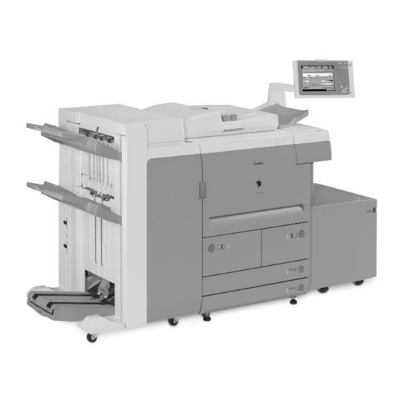
- Page 1 imageRUNNER 7105/7095/7086 SERVICE MANUAL DU7-1166-000 NOVEMBER 2005 REV. 0...
- Page 2 Contents Contents Chapter 1 Introduction 1.1 System Construction ............................1- 1 1.1.1 System Configuration with Input/Output Accessories................ 1- 1 1.1.2 Combination of Delivery Accessories ....................1- 2 1.1.3 System Configuration with Printing/Transmission Accessories ............1- 4 1.1.4 Functions of Printing/Transmission Accessories ................1- 4 1.2 Product Specifications ...........................
- Page 3 Contents 3.2.1 Basic Sequence of Operations (power-on)..................3- 4 Chapter 4 Main Controller 4.1 Construction..............................4- 1 4.1.1 Construction/Functions ........................... 4- 1 4.2 Construction of the Electrical Circuitry ......................4- 2 4.2.1 Main Controller PCB..........................4- 2 4.3 Start-Up Sequence ............................4- 3 4.3.1 Overview ..............................
- Page 4 Contents 5.3.2 Enlargement/Reduction ......................... 5- 10 5.3.2.1 Changing the Reproduction Ratio in Main Scanning Direction..........5- 10 5.3.2.2 Changing the Reproduction Ratio in Sub Scanning Direction <iR7105/7095>.....5- 10 5.3.2.3 Changing the Reproduction Ratio in Sub Scanning Direction <iR7086>....... 5- 10 5.3.3 Controlling the Scanning Lamp ......................5- 11 5.3.3.1 Overview <iR7105/7095>...
-
Page 5: Table Of Contents
Contents 6.3 Various Controls ............................. 6- 3 6.3.1 Controlling the Laser Activation Timing ....................6- 3 6.3.1.1 Turning On and Off the Laser Unit....................6- 3 6.3.1.2 Flow of the BD Signal........................6- 4 6.3.2 Controlling the Intensity of Laser Light ....................6- 5 6.3.2.1 APC Control............................ -
Page 6: Wiring Diagram Of The Major Pcbs
Contents 2.1.3 Installation Space............................. 2- 3 2.1.4 Checking the Contents ..........................2- 4 2.1.5 Order of Installing Accessories ......................2- 6 2.2 Unpacking and Installation ..........................2- 7 2.2.1 Points to Note When Turning On/Off the Main Power ............... 2- 7 2.2.2 Unpacking .............................. - Page 7 Contents 7.7.1 Outline..............................7- 19 7.7.2 Controlling the Developing Assembly ....................7- 20 7.7.3 Controlling the Toner Cartridge Drive Mechanism ................7- 21 7.7.4 Controlling the Developing Bias......................7- 22 7.7.5 Detecting the Toner Level and Controlling the Toner Supply Mechanism ........7- 23 7.8 Transfer Mechanism .............................
-
Page 8: Basic Sequence
Contents 8.1.5 Index Paper Attachment ......................... 8- 3 8.2 Basic Sequence .............................. 8- 4 8.2.1 Right Deck ..............................8- 4 8.2.2 Pickup from the cassette 4........................8- 4 8.3 Detecting Jams ............................... 8- 5 8.3.1 Jam Detection Outline ..........................8- 5 8.3.1.1 Outline .............................. -
Page 9: Construction
Contents 8.11.4 Left Deck Pickup Assembly ........................ 8- 35 8.11.5 Left Deck Pickup Sensor ........................8- 36 8.11.6 Right Deck Pickup Sensor ........................8- 36 8.11.7 Manual Tray Assembly ........................8- 36 8.11.8 Manual Feed Pull-Out Roller Unit ...................... 8- 37 8.11.9 Manual Pickup Roller ...........................8- 38 8.11.10 Manual Feed Roller .......................... -
Page 10: Control Panel
Contents 9.5.5 Internal Delivery Roller .......................... 9- 16 9.5.6 Main Thermistor............................9- 16 9.5.7 Sub Thermistor ............................9- 17 9.5.8 Thermal Switch ............................9- 17 9.5.9 Fixing Heater............................9- 18 9.5.10 Fixing Cleaning Belt ..........................9- 19 9.5.11 Claw Jam Sensor ..........................9- 20 9.5.12 External Delivery Sensor........................ -
Page 11: Overview
Contents 10.5.16 Drum Heater Switch Assembly....................... 10- 18 10.5.17 DC Controller PCB ...........................10- 18 10.5.18 Control Panel Inverter PCB......................10- 19 10.5.19 Control Panel Key Switch PCB ...................... 10- 19 10.5.20 Control Panel Family PCB ......................10- 20 10.5.21 Control Panel CPU PCB........................10- 20 10.5.22 AC Driver PCB ..........................10- 21 10.5.23 All Night Power Supply PCB......................10- 21 10.5.24 Relay PCB ............................ -
Page 12: Making Pre-Checks
Contents 12.1.8 e-RDS setting screen .......................... 12- 3 12.1.9 Sleep operation ............................ 12- 5 12.1.10 Network Setting (Maintenance) ....................... 12- 5 12.1.11 e-RDS Setting (Maintenance)......................12- 6 12.1.12 Trouble shoot............................12- 6 12.1.13 Error message............................ 12- 7 Chapter 13 Maintenance and Inspection 13.1 Periodically Replaced Parts ........................ -
Page 13: Others
Contents 14.6.1 Adjusting the Lower Roller Pressure (nip) ..................14- 17 14.6.2 Points to Note When Mounting the Fixing Heater.................14- 17 14.7 Electrical Components ..........................14- 18 14.7.1 After Replacing the Hard Disk......................14- 18 14.7.2 After Replacing the Main Controller ....................14- 18 14.7.3 After Replacing the DC Controller PCB..................14- 20 14.7.4 After Replacing the Reader Controller PCB .................. -
Page 14: Main Controller Pcb
Contents 15.2.2.1 Motors............................. 15- 5 15.2.3 Fan................................15- 7 15.2.3.1 Fans ..............................15- 7 15.2.3.2 Fans ..............................15- 8 15.2.4 Sensor ..............................15- 10 15.2.4.1 Sensor (reader) <iR7105/7095>....................15- 10 15.2.4.2 Sensor (reader) <iR7086>......................15- 11 15.2.4.3 Sensor 1 ............................15- 12 15.2.4.4 Sensor 2 ............................ -
Page 15: Overview
Contents 17.3 I/O (I/O Display Mode)..........................17- 14 17.3.1 Overview.............................. 17- 14 17.3.2 <DC-CON>............................17- 15 17.3.3 <R-CON>.............................17- 22 17.3.4 <R-CON>.............................17- 24 17.3.5 <FEEDER> ............................17- 25 17.3.6 <FEEDER> ............................17- 28 17.3.7 <SORTER> ............................17- 29 17.3.8 <MN-CONT>............................17- 38 17.4 ADJUST (Adjustment Mode)........................17- 39 17.4.1 COPIER..............................17- 39 17.4.1.1 COPIER Items .......................... -
Page 16: Others
Contents 18.2.3 Making Connections (SST in use) ....................18- 7 18.2.4 Making Connections (USB device in use) ..................18- 7 18.3 Formatting the HDD ........................... 18- 9 18.3.1 Formatting the HDD for All Partition ....................18- 9 18.3.2 Formatting the HDD for Selected Partitions .................. 18- 10 18.3.3 Formatting the Partitions ........................ - Page 17 imageRUNNER 7105/7095/7086 PARTS CATALOG DU7-3150-000 DEC. 2005...
- Page 18 Contents NUMERICAL INDEX iR7086/7095/7105 ................1-1 iR7086/7095/7105 ASSEMBLY LOCATION DIAGRAM ........2-1 EXTERNAL COVERS, PANELS, ETC........2-8 MACHINE FRONT PLATE ...........2-12 INTERNAL COMPONENTS 1 ..........2-14 INTERNAL COMPONENTS 2 ..........2-18 INTERNAL COMPONENTS 3 ..........2-22 INTERNAL COMPONENTS 3 ..........2-26 MACHINE REAR PLATE 1 ..........2-30 MACHINE REAR PLATE 2 ..........2-32 MACHINE BOTTOM PLATE ..........2-34 POWER CORD TERMINAL ASSEMBLY ......2-36...
-
Page 19: Inverter Pcb
Contents LEFT PICK-UP DRIVE ASSEMBLY ........2-101 MULTI FEED DRIVE ASSEMBLY ........2-102 EXTRACTION ROLLER ASSEMBLY ........2-104 DEV. DRIVE ASSEMBLY ..........2-108 CLEANER DRIVE ASSEMBLY ..........2-110 CASSETTE ................2-112 RIGHT PAPER STOCK ASSEMBLY .........2-116 LEFT PAPER STOCK ASSEMBLY ........2-120 CASSETTE HEATER UNIT ..........2-123 CASSETTE PICK-UP ASSEMBLY ........2-124 FRONT DECK RIGHT PICK-UP ASSEMBLY ....2-128 FRONT DECK LEFT PICK-UP ASS'Y .......2-132 MULTI FEEDER ASSEMBLY ..........2-136... - Page 20 FIGURE A ASSEMBLY LOCATION DIAGRAM READER FRAME ASSEMBLY READER ASSEMBLY PRIMARY POLYGON LASER FAN ASSEMBLY 1.5K RIGHT PAPER STOCK ASSEMBLY 1.5K CASSETTE 1.5K LEFT PAPER STOCK ASSEMBLY 1.5K DOOR SWITCH MOUNT ASSEMBLY CONTROL PANEL ASSEMBLY SCANNER ASSEMBLY MIRROR ASSEMBLY 1 MIRROR ASSEMBLY 2 FRONT DECK (RIGHT) PICK-UP ASS'Y...
- Page 21 Canon imageRUNNER 7105, 7095, 7086 service manual Canon imageRUNNER 7105, 7095, 7086 service manual Canon imageRUNNER 7105, 7095, 7086 service manual Canon imageRUNNER 7105, 7095, 7086 service manual Canon imageRUNNER 7105, 7095, 7086 service manual Canon imageRUNNER 7105, 7095, 7086 service manual...