Table of Contents
Advertisement
O
M
PERATOR'S
ANUAL
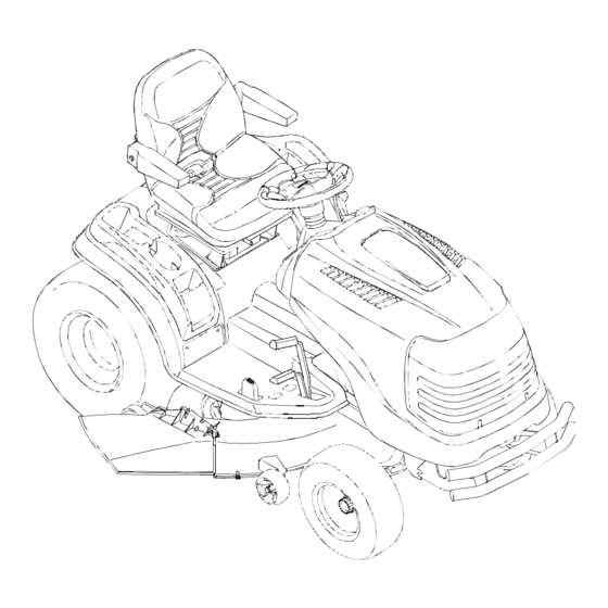
SERIES 2500
TRACTOR
Model Number
GT 2542
IMPORTANT: READ SAFETY RULES AND INSTRUCTIONS CAREFULLY
Warning:
This unit is equipped with an internal combustion engine and should not be used on or near any unimproved forest-
covered, brush-covered or grass-covered land unless the engine's exhaust system is equipped with a spark arrester meeting
applicable local or state laws (if any). If a spark arrester is used, it should be maintained in effective working order by the operator.
In the State of California the above is required by law (Section 4442 of the California Public Resources Code). Other states may have
similar laws. Federal laws apply on federal lands. A spark arrester for the muffler is available through your nearest engine authorized
service dealer or contact the service department, P.O. Box 361131 Cleveland, Ohio 44136-0019.
CUB CADET LLC P.O. BOX 361131 CLEVELAND, OHIO 44136-0019 [www.cubcadet.com]
PRINTED IN U.S.A.
FORM NO. 769-02067
(11/05)
Advertisement
Table of Contents

Related Manuals for Cub Cadet GT 2542


Summary of Contents for Cub Cadet GT 2542
-
Page 1: Model Number
Federal laws apply on federal lands. A spark arrester for the muffler is available through your nearest engine authorized service dealer or contact the service department, P.O. Box 361131 Cleveland, Ohio 44136-0019. CUB CADET LLC P.O. BOX 361131 CLEVELAND, OHIO 44136-0019 [www.cubcadet.com] PRINTED IN U.S.A. -
Page 2: Table Of Contents
TABLE OF CONTENTS Section Page Tractor and Deck Preparation ..... Safe Operation Practices ....Product Graphics ........ Slope Gauge ........To The Owner ........Calling Service Information ....Recording Model & Serial Number..Know Your Tractor ......Operation ..........Adjustments ........Maintenance........ -
Page 3: Tractor And Deck Preparation
TRACTOR AND DECK PREPARATION 1. TRACTOR STEERING WHEEL 2. CONNECT THE BATTERY For shipping purposes, the steering wheel was removed WARNING: Battery posts, terminals and from the steering shaft. Pivot the seat rearward and re- related accessories contain lead and lead move any packaging material from the seat. -
Page 4: Safe Operation Practices
WARNING • The engine exhaust, some of its constituents, and certain vehicle components contain or emit chemicals known to the State of California to cause cancer, birth defects or other reproductive harm. • This unit is equipped with an internal combustion engine and should not be used on or near any unimproved forest-covered, brush-covered, or grass-covered land unless the engine’s exhaust system is equipped with a spark arrester meeting applicable local or state laws (if any). - Page 5 3. Do not mow on wet grass. Reduced traction could 26. Use only accessories approved for this machine by Cub Cadet. Read, understand and follow all cause sliding. instructions provided with the approved accessory.
- Page 6 Never fill containers inside a vehicle or on a truck unit should be serviced professionally by an or trailer bed with a plastic liner. Always place authorized Cub Cadet Dealer. containers on the ground away from your vehicle before filling.
- Page 7 5. Check the blade(s) and engine mounting bolts at 10. Never attempt to make adjustments or repairs to frequent intervals for proper tightness. Also, the machine while the engine is running. visually inspect blade(s) for damage (e.g., 11. Grass catcher components and the discharge excessive wear, bent, cracked).
-
Page 8: Product Graphics
PRODUCT GRAPHICS ing, painted over or can no longer be read. Replace- ment safety graphics are available through your Keep product safety graphics (decals) clean. Replace dealer. any safety graphic that is damaged, destroyed, miss- STARTING INSTRUCTIONS BE FAMILIAR WITH CONTROLS BEFORE D A N G E R STARTING ENGINE AND OPERATING. -
Page 9: Slope Gauge
SLOPE GAUGE... -
Page 10: To The Owner
The dealer has trained service personnel familiar with the latest servic- ing information, is equipped with the latest tools, and has a complete line of genuine Cub Cadet service parts which assure proper fit and high quality. -
Page 11: Know Your Tractor
SECTION I. KNOW YOUR TRACTOR J. Reverse Control Pedal A. Indicator Panel/Hour Meter B. Hour Meter/Battery Display K. Seat Adjustment Lever C. Power Take-Off (PTO) Control Switch L. Lift Handle D. Key Switch Module M. 12V Power Outlet E. Throttle Control Lever N. - Page 12 KEY SWITCH MODULE If this indicator and display come on during oper- ation, check the battery and charging system for possible causes and/or contact your Cub Cadet INDICATOR dealer. REVERSE LIGHT...
- Page 13 • START — Energizes the starter motor to crank To engage the cruise control, depress the forward con- and start the tractor engine. Release the key as trol pedal to attain your desired speed; then push the soon as the engine starts and the key will return parking brake/cruise control lever downward.
- Page 14 If the interlock sys- tem should ever malfunction, do not operate the trac- tor. Contact your authorized Cub Cadet Dealer. The safety interlock system prevents the engine from cranking or starting unless the brake pedal is fully de- Latch Bracket pressed, and the PTO switch is in the “OFF”...
-
Page 15: Operation
SECTION II. OPERATION WARNING: Before you operate the trac- NOTE: Purchase gasoline in small quantities. Do not tor, study this manual carefully. use gasoline left over from the previous season, to Familiarize yourself with the operations minimize gum deposits in the fuel system. of all the instruments and controls. - Page 16 IMPORTANT: If the starter does not turn the engine TRACTOR BREAK-IN PROCEDURE over, shut off starter immediately. Do not make further attempts. Contact your Cub Cadet dealer. IMPORTANT: Never operate a new engine immedi- ately under full load. Break it in carefully as shown in 7.
- Page 17 DRIVING THE TRACTOR 5. Disengage the cruise control using one of the following methods: NOTE: Avoid sudden starts, excessive speed and sud- den stops. • Depress the brake pedal to disengage the cruise control and stop the tractor. WARNING: Do not leave the seat of the •...
- Page 18 STOPPING THE TRACTOR Operate the PTO clutch as follows: 1. Move the throttle control lever to approximately the WARNING: Always engage the brake mid throttle position. pedal lock, push the PTO switch to the “OFF” position, lower the equipment and 2.
- Page 19 USING THE “REVERSE CAUTION MODE” KEY MODE” (Yellow) position of the key switch POSITION module. Refer to Figure 11. NOTE: Mowing in reverse is not recommended. 3. Depress “REVERSE PUSH BUTTON” (Orange/Triangular Button) at the top/right corner The “REVERSE CAUTION MODE” position of the key of the key switch module.
-
Page 20: Adjustments
If brake rod must be increased. adjustment does not correct the problem, see your 2. Release the brake pedal lock. If the tractor cannot authorized Cub Cadet dealer. be pushed forward or rearward, the braking force must be decreased. - Page 21 WHEEL ALIGNMENT 5. Disconnect the front ball joints from the steering arms by removing the hex lock nuts (Refer to The front wheels should toe-in approximately 1/8 to Figure 15). Manually move each wheel to achieve 1/4 inch, as measured across dimensions A and B the required toe-in and equal D measurements.
- Page 22 2. Raise the rear of the tractor, so that the rear tires are PIVOT AXLE at least one inch above the surface, and set it on ADJUSTMENT BOLTS jack stands. Make certain the jack stands are posi- tioned to balance the tractor and prevent tipping. WARNING: The operator presence safety LOCK circuit will stop the engine if the seat is...
- Page 23 CONTROL 1. Front Control Rod 2. Rear Control Rod 3. Hex Tap Screw 4. Hex Wash Hd Tapp Screw 5. Control Arm 6. Control Arm Pin 7. Neutral Arm 8. Centering Pin 9. Neutral Return Adjust. Brkt. 10. Internal Cotter Pin Figure 17 Adjusting the Control Rod ADJUSTING LIFT ASSIST SPRING TENSION...
- Page 24 CARBURETOR ADJUSTMENTS NOTE: Carburetor adjustments should be made only after the engine has warmed up. WARNING: When making adjustments to the carburetor while the engine is run- 1. Start the engine and run at half throttle for 5 to 10 ning, disengage the PTO clutch and minutes to warm up.
-
Page 25: Maintenance
SECTION IV. MAINTENANCE ENGINE MAINTENANCE • Always keep the oil level at or near the “F” mark on the dipstick. If the oil is low, add oil of the proper Maintenance, repair, or replacement of the emission type up to the “F” mark. Always check the oil level control devices and systems, which are being done at with the dipstick before adding more oil. - Page 26 The filter, part number KH-12-050-08, can 6. Remove the filter by turning it counterclockwise be obtained from your Cub Cadet dealer. using an automotive type filter wrench to loosen. Refer to the MAINTENANCE CHART and the 7. Allow the old oil to completely drain from the LUBRICATION TABLE for information regarding the engine crankcase into the container below.
- Page 27 10. Apply a light coating of clean oil on the gasket of CHECKING TRANSMISSION OIL LEVEL the new oil filter. Thread the filter on by hand until NOTE: Check the oil level only while the engine is the gasket contacts the oil filter adapter, then stopped and the tractor is level.
- Page 28 The filter, part number 923- minutes. Shut the engine off, then check for leaks 3014, can be obtained from your Cub Cadet dealer. and re-check the oil level in the transmission case. Refer to the LUBRICATION TABLE for information...
- Page 29 4. Saturate the foam precleaner with new engine oil. 5. When servicing the air cleaner, check the air Squeeze out all excess oil. cleaner base. Make sure it is secured and not bent or damaged. Also check the element cover for damage or improper fit.
- Page 30 FUEL FILTER 6. Align the socket tab with the notch of the reflector housing; then push the socket inward and turn as WARNING: Do not replace the fuel filter necessary to lock the socket in the housing: when engine is hot. 7.
- Page 31 MAINTENANCE OF BATTERY When installing the battery, connect the battery cables in the following order: The tractor is shipped with a wet battery — the battery acid has already been added and the battery sealed. Battery Installation: Although the battery is maintenance free, the following 1.
-
Page 32: Jump Starting
CHARGING THE BATTERY Improperly inflated tires will also affect the leveling of the mower deck and quality of cut. Test and, if necessary, recharge the battery after the tractor has been stored for a period of time. Inflate the front and rear tires as shown in the following table: •... -
Page 33: Mower Deck
SECTION V. MOWER DECK This section contains adjustment, removal, installation, 5. Position the mower blades so that the ends of each and maintenance information for the 42-inch mower blade face the right and left sides of the tractor deck. Instructions for installation and removal of the (See Figure 28). - Page 34 8. Side-to-side leveling is obtained utilizing the 3. Measure and record the distance from the front adjustment ferrule and right hand lift link rod (See cutting edge to the ground (measurement A), and Figure 30). from the rear cutting edge to the ground (measurement B), for each of the blades.
- Page 35 GAUGE WHEEL ADJUSTMENT wheel into the adjustment index hole that pro- vides approximately 1/2" clearance between WARNING: Before making any adjust- the wheel and level surface. Secure with the ments, place the PTO switch in the “OFF” lock nut. position, engage the brake pedal lock, e.
- Page 36 bracket and release the spring tension by rotating WARNING: The exhaust system is HOT. the lever out and rearward (See Figure 35). To avoid personal injury, allow the engine and exhaust system to cool before proceeding with the following LEVER STOP BRACKET PTO belt removal instructions.
- Page 37 6. Pull the deck support pins outward, turn downward and release so both spring-loaded pins are held in TRACTOR the disengaged position against the outer surface LATCH RECEIVER of the rear deck brackets (See Figure 40). (BOTH SIDES) DECK QUICK ATTACH FRONT LIFT ROD/BRACKET...
- Page 38 INSTALLATION OF MOWER DECK quick-attach rod. Slide the shoulder bolts on each side of the front lift rod/bracket assembly fully into WARNING: Before performing the mower the left and right tractor latch receivers. Release deck installation, place the PTO switch in the tractor quick-attach rod to capture the front lift the “OFF”...
- Page 39 6. If not already done, pull the deck support pins are fully extended through the lift links to prevent the outward, turn downward and release so both mower deck from disengaging the lift links while spring-loaded pins are held in the disengaged mowing.
- Page 40 11. Pass the PTO belt downward, inside the tractor LEVER STOP frame, until the belt is below the two tractor front BRACKET lower pulleys. Twist the two sides of the PTO belt IDLER ARM LEVER 1/4 turn inward to engage the narrow sides of the belt into the grooves of the two tractor front-lower pulleys (See Figure 51).
- Page 41 • From the tractor operator’s seat, start the engine Use a 1-1/8" wrench to remove the hex flange nut that and engage the PTO. Allow to run as needed. secures the blade to the spindle assembly. Disengage the PTO and stop the engine. After replacing the blades, apply grease to the •...
- Page 42 SPINDLE DRIVE BELT REPLACEMENT D. INSTALLING MULCHING PLUG In order to replace the spindle drive belt, refer to WARNING: Before installing the mulch- Figure 56 and Figure 57 and proceed as follows: ing plug, place the PTO switch in the “OFF”...
-
Page 43: Off-Season Storage
SECTION VI. OFF-SEASON STORAGE If the machine is to be inoperative for a period longer 2. If emptying the fuel system: than days, following procedures WARNING: Do not drain fuel when the recommended: engine is hot. Allow the engine adequate WARNING: Never store the tractor with time to cool. -
Page 44: Mowing
SECTION VII. MOWING MOWING WARNING: To avoid possible injury, do not allow anyone in the area opposite the discharge chute while mowing. Although the area has been supposedly cleared of foreign objects, small objects may be picked up and discharged by the mower. Never direct the discharge of material toward bystanders or allow anyone near the machine while in operation. -
Page 45: Optional Equipment And Accessories
Refer to the allied equipment can be purchased from, and installed attachment guide for a complete description of by, your authorized Cub Cadet dealer. equipment and required components that can be utilized with your tractor. -
Page 46: Maintenance Chart
MAINTENANCE CHART 10 hours 50 hours 100 hours Operation to Before or once Every or twice Before be performed each use a month 25 hours a season yearly storage Check engine oil level Fill fuel tank Change engine oil After first 25 every 100 hours &... -
Page 47: Lubrication Table
Cub Cadet Drive System Fluid Plus and transaxle with before needed 6 qts NOTE: Cub Cadet Drive System Fluid Plus is specially filter each formulated for this application. If any other oil is used Cub Cadet will not be responsible for substandard performance. -
Page 48: Lubrication Guide
LUBRICATION GUIDE... - Page 49 LUBRICATION GUIDE —Before Each Use 1. Engine filler cap and Check the oil (with the engine stopped) and add sufficient new oil to bring it to dipstick the “FULL” mark on the dipstick. Do not overfill. Do not operate the engine if the oil level is below the “LOW”...
-
Page 50: Trouble Shooting
TROUBLE SHOOTING Possible Cause Possible Remedy HARD TO START No gasoline in fuel tank or carburetor..... Fill the tank with gasoline. Check the fuel line, carburetor and fuel filter. Fuel line or carburetor clogged ....... Clean the fuel line and carburetor with a commercial carburetor cleaner. - Page 51 TROUBLE SHOOTING Possible Cause Possible Remedy LACK OF POWER Air cleaner clogged ..........Service the air cleaner element. Refer to “MAINTE- NANCE.” Engine overload ............Reduce the load. Engine overheated..........Make sure the air intake screen, shrouding, and engine cooling fins are free of accumulated dirt and debris. Refer to “MAINTENANCE.”...
-
Page 52: Specifications
Engine Speed (governed) Low Speed ..............1200 RPM High Speed (no load) ........... 3600 RPM ± 75 Ignition ................Battery Spark Plug Gap (Cub Cadet No. 759-3336) ....030 in. ELECTRICAL SYSTEM System Voltage .............. 12 volt neg. ground Battery ................725-1707D Alternator ................ -
Page 53: Emission Control Systems Warranty
KOHLER CO. FEDERAL AND CALIFORNIA EMISSION CONTROL SYSTEMS LIMITED WARRANTY SMALL OFF-ROAD EQUIPMENT ENGINES The U.S. Environmental Protection Agency (EPA), the California Air Resources Board (CARB), and Kohler Co. are pleased to explain the Federal and California Emission Control Systems Warranty on your small off-road equipment engine (herein engine). For California, engines produced in 1995 and later must be designed, built and equipped to meet the state’s stringent anti-smog standards. -
Page 54: Warranty
Cub Cadet LLC at P.O. Box 361131, Cleveland, Ohio 44136-0019, or call 1-877-282- 8684, or MTD Canada Ltd. KITCHENER, ON N2G 4J1; Phone 1-800-668-1238... -
Page 56: Maintenance Parts Chart
MAINTENANCE PARTS CHART MODEL GT 2542 SERIES 2500 20 HP KOHLER Engine Oil Requirements approx. . . 4 pints Part No. ENGINE OIL Cub Cadet engine oil Ambient temperature viscosity (Grade SG,SH,SJ or higher) Above +32°F SAE 10W30 737-3030A (10W30) Below +32°F...
Need help?
Do you have a question about the GT 2542 and is the answer not in the manual?
Questions and answers
how good is this lawn traqctor
The Cub Cadet GT2542 is considered a good lawn tractor, especially for its price. It is part of the 2500 series, which is generally regarded as a great value. The 42-inch twin-blade deck may not cut as efficiently as larger three-blade decks, but it is suitable for smaller lots, such as one acre. Users appreciate its solid build quality, reliable frame, and drive system. The model is also backed by a three-year warranty, which is honored well. Some users prefer it over other brands like John Deere, citing better construction and longer-lasting parts availability.
This answer is automatically generated