Table of Contents
Advertisement
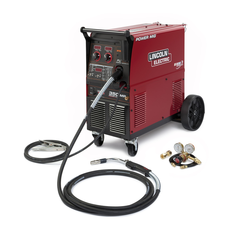
POWER MIG
For use with machine Code Numbers:
This manual covers equipment which is no
longer in production by The Lincoln Electric Co.
Speci cations and availability of optional
features may have changed.
Safety Depends on You
Lincoln arc welding and cutting
equipment is designed and built
with safety in mind. However,
your overall safety can be
increased by proper installation
... and thoughtful operation on
your part. DO NOT INSTALL,
OPERATE OR REPAIR THIS
EQUIPMENT WITHOUT READ-
ING THIS MANUAL AND THE
SAFETY PRECAUTIONS CON-
TAINED THROUGHOUT. And,
most importantly, think before
you act and be careful.
• Sales and Service through Subsidiaries and Distributors Worldwide •
Cleveland, Ohio 44117-1199 U.S.A. TEL: 216.481.8100 FAX: 216.486.1751 WEB SITE: www.lincolnelectric.com
OPERATORʼS MANUAL
• World's Leader in Welding and Cutting Products •
350MP
®
11147For use with machine
Copyright © Lincoln Global Inc.
IM859
May, 2012
Advertisement
Table of Contents
Troubleshooting

Related Manuals for Lincoln POWER MIG 350MP


Summary of Contents for Lincoln POWER MIG 350MP
- Page 1 May, 2012 For use with machine Code Numbers: 11147For use with machine This manual covers equipment which is no longer in production by The Lincoln Electric Co. Speci cations and availability of optional features may have changed. Safety Depends on You...
- Page 2 351040, Miami, Florida 33135 or CSA Standard W117.2-1974. A Free copy of “Arc Welding Safety” booklet E205 is available from the Lincoln Electric Company, 22801 St. Clair Avenue, Cleveland, Ohio 44117-1199. BE SURE THAT ALL INSTALLATION, OPERATION, MAINTENANCE AND REPAIR PROCEDURES ARE PERFORMED ONLY BY QUALIFIED INDIVIDUALS.
-
Page 3: Electric Shock Can Kill
SAFETY ARC RAYS can burn. ELECTRIC SHOCK can 4.a. Use a shield with the proper filter and cover kill. plates to protect your eyes from sparks and 3.a. The electrode and work (or ground) circuits the rays of the arc when welding or observing are electrically “hot”... - Page 4 SAFETY WELDING and CUTTING CYLINDER may explode SPARKS can if damaged. cause fire or explosion. 7.a. Use only compressed gas cylinders 6.a. Remove fire hazards from the welding area. containing the correct shielding gas for the If this is not possible, cover them to prevent process used and properly operating the welding sparks from starting a fire.
- Page 5 SAFETY 5. Toujours porter des lunettes de sécurité dans la zone de PRÉCAUTIONS DE SÛRETÉ soudage. Utiliser des lunettes avec écrans lateraux dans les zones où lʼon pique le laitier. Pour votre propre protection lire et observer toutes les instructions et les précautions de sûreté...
- Page 6 Electric for advice or information about their use of our products. We respond to our customers based on the best information in our posses- sion at that time. Lincoln Electric is not in a position to warrant or guarantee such advice, and assumes no liability, with respect to such infor- mation or advice.
-
Page 7: Table Of Contents
TABLE OF CONTENTS Page ________________________________________________________________________ Installation........................Section A Technical Specifications.......................A-1 Safety Precautions .......................A-2 ® Uncrating the POWER MIG 350MP ...................A-2 Location..........................A-2 Input Power, Grounding and Connection Diagrams .............A-2, A-3 Gun and Cable Installation ....................A-4 Shielding Gas ......................A-4 thru A-5 Installing TIG Torch ......................A-5, A-6 ________________________________________________________________________________ Operation.........................Section B Safety Precautions .......................B-1... -
Page 8: Installation
INSTALLATION TECHNICAL SPECIFICATIONS – POWER MIG 350MP ® INPUT – SINGLE PHASE ONLY Standard Voltage/Frequency Input Current @ 230Amp Rated Output Input Current @ 300 Amp Rated Output 208/230/460/575/50/60 Hz 50/48/25/20 Amps 76/64/37/29 Amps RATED OUTPUT Input Voltage/Frequency Hz Duty Cycle Amps Volts at Rated Amperes 208/60... -
Page 9: Safety Precautions
INSTALLATION ONLY QUALIFIED PERSONNEL SHOULD Read entire installation section before starting installation. INSTALL, USE OR SERVICE THIS EQUIP- MENT. SAFETY PRECAUTIONS UNCRATING THE POWER MIG ® WARNING 350MP ELECTRIC SHOCK can kill. Cut banding and lift off cardboard carton. Cut banding •... -
Page 10: Auxiliary Power Receptacles
INSTALLATION FIGURE A.1 — Triple Voltage Machine Input Connections AUXILIARY POWER RECEPTACLES ® 3. The POWER MIG 350MP is shipped with a 10ft.(3.05m) input cable and plug connected to the welder. Using the instructions in Figure A.2, have a (15 Amp, 120 Volt Receptacle) The receptacle is UL qualified electrician connect the receptacle or cable and CSA approved. -
Page 11: Gun And Cable Installation
INSTALLATION GUN & CABLE ASSEMBLY INSTALLED GUN AND CABLE INSTALLATION INTO THE POWER MIG A Magnum 300 gun and 15Ft.(4.6m) cable are provid- 1. Unscrew knurled screw on the drive unit front end ® ed with the POWER MIG 350MP. A Magnum cable (inside wire feed compartment) until tip of screw no liner for .035-.045"... -
Page 12: Installing Tig Torch
INSTALLATION INSTALLING TIG TORCH DO NOT ATTACH THE REGULATOR IF OIL, GREASE OR DAMAGE IS PRESENT! Inform your gas supplier of this condition. Oil or grease in the ® The POWER MIG 350MP is programmed to allow it presence of high pressure oxygen is explosive. to be used as a DC TIG welder. - Page 13 INSTALLATION FIGURE A.4 TORCH POWER CABLE TO NAGATIVE STUD(-) REMOTE CONTROL WORK RECEPTACLE CABLE POSITIVE STUD (+) TO POSITIVE STUD(+) NEGATIVE STUD (-) WORK CLAMP GAS SUPPLY CONNECTION WORK PIECE FOOT AMPTROL (OPTIONAL) TO REMOTE CONTROL RECEPTACLE CONNECTOR TO GAS SUPPLY HOSE FIGURE A.5 GAS REGULATOR...
-
Page 14: Operation
OPERATION Read entire Operation section before COMMON WELDING ABBREVIA- operating the POWER MIG ® 350MP. TIONS WARNING ELECTRIC SHOCK can kill. • Wire Feed Speed • Do not touch electrically live parts or electrode with skin or wet clothing. Insulate yourself •... -
Page 15: Product Description
OPERATION PRODUCT DESCRIPTION Other features Optional kits are available for push-pull welding, spool ® The POWER MIG 350MP is a complete semiauto- gun operation, push feeding of 3/64 aluminum with the ® matic multi-process DC arc welding machine offering standard POWER MIG 350MP gun and wire feeder. - Page 16 OPERATIONS 5. MULTI-PROCESS PANEL - This panel enables selection 2. VOLT / TRIM METER - This meter displays either of weld modes as well as adjustment of certain weld the voltage or trim value depending on the status of parameters within each weld mode. the machine.
-
Page 17: Setting And Configuring The Power Mig ® 350Mp For Welding
OPERATION SETTING AND CONFIGURING THE POWER ® 350MP FOR WELDING • Check that the electrode polarity is correct for the process and turn the Power Switch to the "ON" position. After the "boot-up" period (approximately 20 seconds), the POWER ® 350MP will default to the last preset weld mode that was active when the machine was powered down. -
Page 18: Multi-Process Panel Functions
OPERATION Run-In MULTI-PROCESS PANEL FUNCTIONS • The Run-In function offers the ability to set a wire feed speed, from trigger until an arc is established, that is independent of Weld Mode the Welding or Start wire feed speed. Setting a Run-In WFS Setting the Weld Mode is selecting the proper program lower than the welding WFS avoids stubbing problems when from the ones available in the machineʼs memory for a... - Page 19 OPERATION Carbon steel electrodes employed in GMAW-S usually per- Arc Control (See Table B.2) There are no specific unit values offered because the setting form best when the droplet size is regulated by pinch to reduce the droplet size transferred with each short-circuit of this feature largely depends upon operator preference.
-
Page 20: Wire Drive Roll
OPERATION In the case of special waveforms designed for pulsed weld- • In the GMAW, FCAW, and Power weld modes, crater ing aluminum, Pulse on Pulse™, the effect is similar to what WFS and voltage are adjustable using the control knobs occurs with standard pulse. -
Page 21: Procedure For Changing Drive And Idle Roll Sets
OPERATION PROCEDURE FOR CHANGING 5. Rotate the spindle and adapter so the retaining spring is at the 12 o'clock position. DRIVE AND IDLE ROLL SETS 6. Position the Readi-Reel so that it will rotate in a direc- 1. Turn off the power source. tion when feeding so as to be de-reeled from top the of 2. -
Page 22: Feeding Wire Electrode
OPERATION 4. Re-install the Retaining Collar. Make sure that the The pressure arm controls the amount of force the drive Release Bar “pops up” and that the collar retainers rolls exert on the wire. Proper adjustment of pressure fully engage the retaining ring groove on the spin- arm gives the best welding performance. -
Page 23: Avoiding Wire Feeding Problems
9. Rotate the gun bushing until the thumb screw hole aligns with the thumb screw hole in the feed plate. e. Use only clean, rust-free electrode. Lincoln elec- Slide the gun receiver bushing into the wire drive trodes have proper surface lubrication. -
Page 24: Special Welding Processes Available
B-11 OPERATION B-11 SPECIAL WELDING PROCESSES Pulsed MIG is an advanced form of welding that takes the best of all the other forms of transfer while minimiz- AVAILABLE ON THE POWER MIG ® ing or eliminating their disadvantages. Unlike short cir- 350MP cuit, pulsed MIG does not create spatter or run the risk of cold lapping. - Page 25 When Arc Control is used in the Pulse on Pulse modes, it does the same things it does in the other Pulse on Pulse™ is a Lincoln process specifically pulsed modes: decreasing the Arc Control decreases designed for use in welding relatively thin (less than the droplet transfer and weld deposition rate.
-
Page 26: Power Mode
The Power Mode™ process was developed by adjust the Volts/Trim knob as follows: Lincoln to maintain a stable and smooth arc at low procedure settings which are needed to weld thin • For steel, listen for the traditional “frying egg”... -
Page 27: Accessories
ACCESSORIES DRIVE ROLL KITS Part No. Length Wire Size Metric Wire Size .035 – .045" K470-1 10' (3.0 m) 0.9 – 1.2 mm ◊ K470-2 15' (4.6 m) .035 – .045" 0.9 – 1.2 mm Refer to Table C.1 for various drive roll kits that are K470-4 15' (4.6 m) .052 –... - Page 28 ACCESSORIES Non-Synergic Weld Modes (Mode 5) Remember: The dialed in SPD value at the POWER ® • Voltage is adjustable at the power source. The does not control the WFS at the spool 350MP ® right control knob on the power source will gun.
-
Page 29: Maintenance
MAINTENANCE SAFETY PRECAUTIONS CONTACT TIP AND GAS NOZZLE INSTALLATION WARNING a. Choose the correct size contact tip for the elec- ELECTRIC SHOCK can kill. trode being used (wire size is stenciled on the side of the contact tip) and screw it snugly into the gas •... -
Page 30: Liner Removal And Replacement
MAINTENANCE CAUTION 5. Seat Liner bushing into back of gun. Secure Liner by tightening set screw. Do not install the gas dif- Excessive pressure at the start may cause the dirt fuser at this time. to form a plug. ----------------------------------------------------------- 6. - Page 31 TROUBLESHOOTING WARNING Service and Repair should only be performed by Lincoln Electric Factory Trained Personnel. Unauthorized repairs performed on this equipment may result in danger to the technician and machine operator and will invalidate your factory warranty. For your safety and to avoid Electrical Shock, please observe all safety notes and precautions detailed throughout this manual.
- Page 32 CAUTION If for any reason you do not understand the test procedures or are unable to perform the tests/repairs safely, contact your Local Lincoln Authorized Field Service Facility for technical troubleshooting assistance before you proceed. ® POWER MIG...
-
Page 33: Troubleshooting
CAUTION If for any reason you do not understand the test procedures or are unable to perform the tests/repairs safely, contact your LOCAL AUTHORIZED LINCOLN ELECTRIC FIELD SERVICE FACILITY for assistance before you proceed. ® POWER MIG... -
Page 34: Troubleshooting
5. Check spindle for ease of rotation. CAUTION If for any reason you do not understand the test procedures or are unable to perform the tests/repairs safely, contact your LOCAL AUTHORIZED LINCOLN ELECTRIC FIELD SERVICE FACILITY for assistance before you proceed. ® POWER MIG... - Page 35 CAUTION If for any reason you do not understand the test procedures or are unable to perform the tests/repairs safely, contact your LOCAL AUTHORIZED LINCOLN ELECTRIC FIELD SERVICE FACILITY for assistance before you proceed. ® POWER MIG 350MP...
-
Page 36: Fault Codes
CAUTION If for any reason you do not understand the test procedures or are unable to perform the tests/repairs safely, contact your Local Lincoln Authorized Field Service Facility for technical troubleshooting assistance before you proceed. ® POWER MIG 350MP... - Page 37 5. Clean or replace contact tip. CAUTION If for any reason you do not understand the test procedures or are unable to perform the tests/repairs safely, contact your Local Lincoln Authorized Field Service Facility for technical troubleshooting assistance before you proceed. ® POWER MIG...
- Page 38 Number Adjustment) CAUTION If for any reason you do not understand the test procedures or are unable to perform the tests/repairs safely, contact your Local Lincoln Authorized Field Service Facility for technical troubleshooting assistance before you proceed. ® POWER MIG...
- Page 39 Factor Number Adjustment) CAUTION If for any reason you do not understand the test procedures or are unable to perform the tests/repairs safely, contact your Local Lincoln Authorized Field Service Facility for technical troubleshooting assistance before you proceed. ® POWER MIG...
- Page 40 5. Machine will reset itself. CAUTION If for any reason you do not understand the test procedures or are unable to perform the tests/repairs safely, contact your Local Lincoln Authorized Field Service Facility for technical troubleshooting assistance before you proceed. ® POWER MIG...
- Page 41 WIRING DIAGRAMS ® POWER MIG 350MP...
- Page 42 DIMENSION PRINT ® POWER MIG 350MP...
- Page 43 NOTES ® POWER MIG 350MP...
- Page 44 NOTES ® POWER MIG 350MP...
- Page 45 Do not touch electrically live parts or Keep flammable materials away. Wear eye, ear and body protection. WARNING electrode with skin or wet clothing. Insulate yourself from work and ground. Spanish No toque las partes o los electrodos Mantenga el material combustible Protéjase los ojos, los oídos y el AVISO DE bajo carga con la piel o ropa moja-...
- Page 46 Keep your head out of fumes. Turn power off before servicing. Do not operate with panel open or WARNING Use ventilation or exhaust to guards off. remove fumes from breathing zone. Spanish Los humos fuera de la zona de res- Desconectar el cable de ali- No operar con panel abierto o AVISO DE...
- Page 47 • World's Leader in Welding and Cutting Products • • Sales and Service through Subsidiaries and Distributors Worldwide • Cleveland, Ohio 44117-1199 U.S.A. TEL: 216.481.8100 FAX: 216.486.1751 WEB SITE: www.lincolnelectric.com...
Need help?
Do you have a question about the POWER MIG 350MP and is the answer not in the manual?
Questions and answers