
Related Manuals for Omega 24


Summary of Contents for Omega 24
- Page 1 User’s Guide ® http://www.omega.com e-mail: info@omega.com CL23A, 24, 25, 26, 27 Digital Calibrator/Thermometer...
- Page 2 CE mark to every appropriate device upon certification. The information contained in this document is believed to be correct but OMEGA Engineering, Inc. accepts no liability for any errors it contains, and reserves the right to alter specifications without notice.
-
Page 3: Table Of Contents
TABLE OF CONTENTS General Information... 2 Common Specifications... 2 Unique Specifications ... 5 Features... 6 Manual Addenda ... 6 Unpacking Your Unit... 7 Safety Information ... 7 Safety Precautions ... 7 Battery Installation/Replacement... 9 Memory Backup... 10 Operation with Rechargeable Battery... 10 Operating Instructions... -
Page 4: General Information
It is recommended that you read this manual thoroughly, especially the sec- tions on safety, prior to operating these instruments. COMMON SPECIFICATIONS THERMOMETER INPUTS: THERMOCOUPLE; Miniature TC jack. RTD, OHMS, THERMISTOR; T-series instrumentation connector. CALIBRATOR OUTPUTS: THERMOCOUPLE; Miniature TC jack. RTD, OHMS, THERMISTOR;... - Page 5 RTD; ±0.2°F (rdg ≥ – 50°F) RTD; ±0.5°F (rdg < – 50°F) RTD; ±0.2°F ±0.04% rdg (meter mode) THERMISTOR; ±0.5F OHMS; ±0.02% range * Exclusive of sensor errors, and lead resistance induced errors. RESOLUTION: TEMPERATURE; 0.1°/1° F/C RESOLUTION: OHMS; 0.01Ω/0.1Ω/1Ω REPEATABILITY (1 week at constant ambient temperature): K, J, T, E, N;...
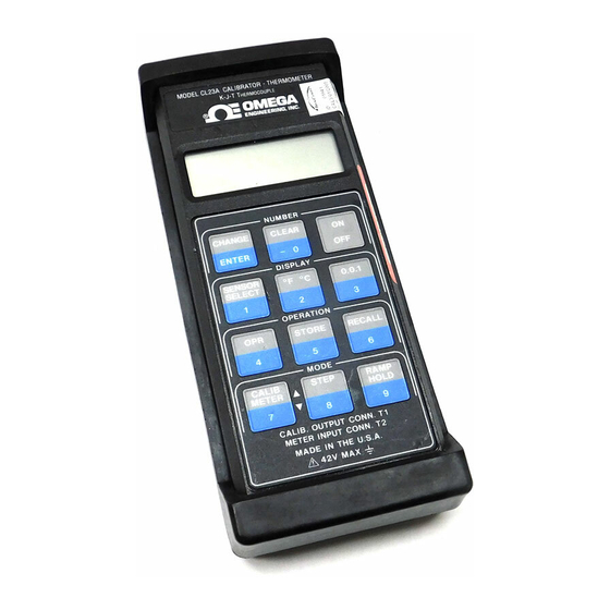
- Page 6 KEYPAD: 12 momentary switches with tactile feedback select; • On/Off • Change/Enter • Clear/–0 • Sensor Select/1 • °F/°C/2 • Resolution/3 • Operate/4 • Store/5 • Recall/6 • Calibrator/Meter/Up Ramp/7 • Calibrator Step/Down Ramp/8 • Calibrator Ramp/Meter Hold/9 DISPLAY: 5 digit LCD, 0.4" height, and decimal point. Annunciators; •...
-
Page 7: Unique Specifications
BATTERY LIFE, CONTINUOUS: 10 hrs. typical, alkaline; 3 hrs typical, Ni-Cd (rechargeable). BATTERY INDICATOR: Display indicates BAT when less than 10% of life remains. DIMENSIONS, WEIGHT: 7.0" UNIQUE SPECIFICATIONS NOTE: The specifications below are specific to the model(s) as identified by model number. -
Page 8: Features
SENSOR SELECTION: K, J, T, E, N, B, R, S, G, C, D/K, J, T, E, N, B, R, S, L, C, RAMP FUNCTION: Included. • Combination calibrator, thermometer and datalogger. • Function selection and numeric data entered via 12 keyswitch color coded keypad. -
Page 9: Unpacking Your Unit
UNPACKING YOUR UNIT Remove the Packing List and verify that you have received all equipment. If you have any questions about the shipment, please call the OMEGA Customer Service Department at 1-800-622-2378 or (203) 359-1660. When you receive the shipment, inspect the container and equipment for any signs of damage. - Page 10 Do not touch a temperature probe sheath when measuring excessively high or low temperatures, or toxic substances. Do not attempt to measure temperatures beyond the range of the probe being used. Probe damage or personal injury could result from exceeding a probe's maximum temperature rating.
-
Page 11: Battery Installation/Replacement
Where the meter and calibrator connectors are simultane- ously wired into a system lacking the above isolation, it is necessary to use an "ungrounded" (i.e. electrically isolated) probe at the thermometer input. BATTERY INSTALLATION/REPLACEMENT A 9V alkaline battery is supplied with the instrument but not installed. Read the following installation instructions before attempting to install or remove the battery. -
Page 12: Memory Backup
2. Remove the old battery by lifting the battery extractor loop. 3. Place the new battery in the battery compartment. Be sure to observe proper polarity. 4. Re-install the battery cover before resuming use of the instrument. NOTES: • Less than 10% of battery life remains when the BAT annuncia- tor turns on. -
Page 13: Operating Instructions
OPERATING INSTRUCTIONS 1. DIAGNOSTICS AND ERROR MESSAGES Unit self-diagnostics provide fault condition readouts which are described below: PROBLEM: Blank display, unit does not power-up. BAT Annunciator. Display reads OPEN. Display reads E1 momentarily. Display reads E2 momentarily. Display reads HI. Display reads LO. - Page 14 Figure 2. Keypad Figure 3. Display Test If the unit is turning on for the first time after a new battery is installed, it will automatically default to the METER mode (ie. temperature measurement operation). It also defaults to K-type thermocouples, and °F readings with 0.1°...
-
Page 15: Meter Mode Operation (Thermocouple)
NOTE: To obtain full accuracy, allow 1-2 minutes after connect- ing a thermocouple plug, for thermal setting. If the instrument is to be used as a thermometer or ohmmeter, refer to the Meter Mode Operation section for detailed instructions. For use as a tem- perature-calibrator or ohms simulator, refer to Calibrator Mode Operation. -
Page 16: Meter Mode Operation (Rtd, Thermistor, Ohms)
6. Select display resolution with 0.1°/1° key. NOTE: Set-up is retained during power-off. Hold: Meter readings can be put on hold at any time by depressing the HOLD key. At this time, the HOLD annunciator turns on, the reading is frozen, and all keys (except ON/OFF and HOLD) are locked out. -
Page 17: Data Logging & Recall
Figure 6. 4-Wire Resistance Measurement Lead resistance errors are compensated for in 3-wire configurations. However full compensation requires equal resistance in each lead. This configuration is common with 100-ohm RTDs. In 4-wire configurations, accuracy is unaffected by lead resistance, and resistance differences between leads. - Page 18 2. Next depress the keypad number corresponding to the desired location. Note that the annunciator for this location turns on, and the memory con- tents are displayed. 3. Several stored readings can be randomly recalled by a key sequence such as: Calibrator Thermometer (output) (input) Figure 7.
-
Page 19: Calibrator Mode Operation (Thermocouples)
eg. RECALL 3 RECALL 5 RECALL 2 etc. 4. To return the meter to the operate mode, depress OPR after recalling the last reading. All active location annunciators will turn on again, together with the OPR annunciator. NOTE: Recalling data from unused (ie, empty) locations will give a zero reading. -
Page 20: Calibrator Mode Operation (Rtd, Thermistor, Ohms)
°F CHANGE/ENTER CHANGE/ENTER °C (Display reads 25°C) 7. CALIBRATOR MODE OPERATION (RTD, Thermistor & Ohms) Set-Up: 1. Connect measurement equipment under test (eg. RTD thermometer, ohmmeter, etc.) to the instrument as shown in Figures 8, 9, or 10. - Page 21 (current) source Figure 8. 2-Wire Resistance Simulation Figure 9. 3-Wire Resistance Simulation NOTE: Colors indicated apply to Model 84937 Calibration Cable. Figure 10. 4-Wire Resistance Simulation Calibrator (out) Thermometer (in) I out V out...
-
Page 22: Storage And Recall Of Calibrator Settings
The same performance tradeoffs apply to 2, 3 and 4-wire simulations as to 2, 3, and 4-wire measurements. Refer to RTD, Thermistor and Ohms Meter-Mode section above for wiring guidelines. 2. Set instrument to CALIBRATOR mode. 3. Use the sensor-select key to set the instrument to the appropriate func- tion and range. - Page 23 To Recall Outputs: 1. While in the CALIB OPR mode, set-ups saved earlier in memory can be recalled to program the calibrator output. First depress the RECALL key to recall a set-up. Note that the RCL annunciator turns on, OPR turns off, and all memory locations annunciators are blanked.
-
Page 24: Step Function
9. STEP FUNCTION When operating in the CALIBRATOR mode, the STEP key will sequentially recall data stored in memory (up to 10 steps). At each step, the calibrator will display and output these parameters. The STEP function is non-functional in METER mode. -
Page 25: Service Information
(RTD, thermistor, ohms) follow first the Thermocouple Calibration procedure, then the Resistance Calibration procedure. A. THERMOCOUPLE CALIBRATION Test Equipment Required: 1. Thermocouple simulator (OMEGA CL521, or equivalent) calibrated to ITS-90. 2. Microvolt DMM (OMEGA OM7551, or equivalent) 3. Calibration cables, per Figures 11, 12, 13. - Page 26 NOTE: For calibrators with the older, single-jumper configura- tion, refer to calibration procedure beginning on page 39. 14. Install calibration cover in place of bottom-cover. 15. Re-install battery. 16. Hook up test-equipment, calibration cables, and U.U.T. per Figure 10. 17. Turn on DMM and TC simulator for warmup. Allow at least 30 minutes. 18.
- Page 27 Calibration Adjustments: NOTE: Do not deviate from the calibration adjustment sequence that follows. This will ensure that adjustments to be stored in EEPROM go to the correct locations. 1. Set meter-mode zero and gain adjustments per Table 1. 2. Hit OPR key (RTD annunciator turns off). 3.
- Page 28 Table 1: Meter-Mode Zero & Gain Adjustments Sensor Step Select **G** ** exclusive of noise. ** on EC models, G replaced by L. Calibrate L per J. Table 2: Calibrator-Mode Zero & Gain Adjustments Sensor Step Select **G** ** exclusive of noise. ** on EC models, G replaced by L.
- Page 29 Figure 11. Calibration Setup, Copper Mode. Figure 12. Calibration Setup, Meter Mode. Figure 13. Calibration Setup, Calibrator Mode.
-
Page 30: Resistance Calibration
1. Resistance Decades (General Resistance RTD-100, RTD-500/1000, and RDS-54, or equivalent). 2. Current Source (Fluke 5101B, or equivalent). 3. Digital Multimeter (OMEGA OM7551, or equivalent). 4. Calibration cables per Figure 14. Ambient Conditions: Unit should be calibrated at an ambient temperature of 23°C±1°C, with rela- tive humidity less than 80%. - Page 31 Figure 14. Resistance Calibration Setup...
- Page 32 Calibration Adjustments: NOTE: Do not deviate from the calibration adjustment sequence that follows. This will ensure that adjustments to be stored in EEPROM go to the correct locations. 1. Perform meter-mode adjustments and verifications per Table 3 (use Table 5 for RTD-Thermistor models). 2.
- Page 33 Table 4: Calibration of Calibrator-Mode Resistance Functions (RTD-100/1000) Sensor Step Select RTD-100 RTD-100 RTD-100 RTD-1000 RTD-1000 1,000Ω 1,000Ω 10,000Ω 10,000Ω * exclusive of noise. Table 5: Calibration of Meter-Mode Resistance Functions (RTD-Thermistor) Sensor Step Select RTD-100 RTD-100 RTD-100 1,000Ω 1,000Ω 100,000Ω...
-
Page 34: Calibration Verification
Table 6: Calibration of Calibrator-Mode Resistance Functions (RTD-Thermistor) Sensor Step Select RTD-100 RTD-100 RTD-100 1,000Ω 1,000Ω 100,000Ω 100,000Ω Thermistor Thermistor Thermistor * exclusive of noise. 2. CALIBRATION VERIFICATION Calibration is verified with the same instrument hookups as used for calibra- tion (ie. - Page 35 “Alloy-mode” refers to Thermocouple operations; for example, a Type-K thermocouple is made up of Nickel/Chromium and Nickel/Aluminum alloys. Referring to the OMEGA Calibrator(s) in TC operation, “Alloy-mode” means in effect “other than Copper-mode.” In order to make accurate measure- ments using a thermocouple device one must eliminate erroneous voltage signals.
- Page 36 4. Select type K thermocouple (“K” on display) by pressing the SENSOR SELECT function button until type K is reached. 5. Select the tenth degree display (with a digit appearing after the decimal point on the display) by pressing the 0.0.1 function button. 6.
- Page 37 23. Press the CHANGE function button. The “32.0 °F” display will blink, and “NUM” will appear on the display. 24. Press 1 0 0 0 0 buttons and then press ENTER function button. “NUM” will disappear and “1000.0 °F” will appear, not blinking. The voltmeter should read 1.438 mV.
- Page 38 ALLOY MODE VERIFICATION PROCEDURE FOR THERMOCOUPLE FUNCTIONS Equipment Required: 1. OMEGA Model to be verified. 2. Precision temperature simulator / voltage source. 3. Voltmeter accurate to 1µV resolution. 4. Cable assembly . 1. Start your calibration with a fresh battery.
- Page 39 3. Select the calibrator mode (“CALIB” on display) by pressing the CALIB/METER function button. 4. Select type K thermocouple (“K” on display) by pressing the SENSOR SELECT function button until type K is reached. 5. Select the tenth degree display with a digit appearing after the decimal point on the display) by pressing the 0.0.1 function button.
-
Page 40: Mechanical Parts Diagram
4. MECHANICAL PARTS DIAGRAM... -
Page 41: Calibration Procedures
CALIBRATION PROCEDURES Test Equipment Required: 1. Thermocouple simulator (OMEGA CL25, or equivalent). 2. Microvolt null-meter (Keithley 155, or equivalent) 3. Calibration cover (OMEGA 820-307-4). 4. Calibration cables, T.C. types K, J, T & E (as required) per Figure1 below. 5. Low-thermal (eg. copper) shorting-link for null-meter. - Page 42 NOTE: • With J1 removed, the digital-filters in the U.U.T. are dis- abled. This is to speed up U.U.T. response to calibra- tion adjustments. In this mode ±0.1°F of reading noise is normal. NOTE: • Do not deviate from the calibration adjustment sequence that follows.
- Page 43 23. Select Type-E thermocouple. 24. Turn off U.U.T. 25. Replace T calibration-cable with E calibration-cable. 26. Turn on U.U.T. Allow 2-3 minutes for thermal stabilization. 27. Apply 32°F (Type E). Adjust P1 for a reading of 32.0°F (exclusive of noise).
- Page 44 47. Set both the U.U.T. and TC-simulator to output 32.0°F (Type T). Adjust P1 for a null-meter reading of 0±3µV. 48. Hit OPR key to store T-calib zero adjustment. NOTE: Steps 49 thru 54 apply to Model CL24 only. For Model CL23A go next to step 55.
- Page 45 NOTES...
- Page 46 NOTES...
-
Page 47: Warranty
CONDITIONS: Equipment sold by OMEGA is not intended to be used, nor shall it be used: (1) as a “Basic Component” under 10 CFR 21 (NRC), used in or with any nuclear installation or activity; or (2) in medical applications or used on humans. - Page 48 Where Do I Find Everything I Need for Process Measurement and Control? OMEGA…Of Course! TEMPERATURE Thermocouple, RTD & Thermistor Probes, Connectors, Panels & Assemblies Wire: Thermocouple, RTD & Thermistor Calibrators & Ice Point References Recorders, Controllers & Process Monitors Infrared Pyrometers PRESSURE, STRAIN AND FORCE Transducers &...
Need help?
Do you have a question about the 24 and is the answer not in the manual?
Questions and answers