Kramer VP-440 User Manual
Switcher/scaler
Hide thumbs
Also See for VP-440:
- User manual (65 pages) ,
- Quick start manual (2 pages) ,
- User manual (65 pages)

Related Manuals for Kramer VP-440


Summary of Contents for Kramer VP-440
-
Page 1: User Manual
USER MANUAL MODEL: VP-440 Presentation Switcher/Scaler P/N: 2900-300476 Rev 6 www.kramerAV.com... -
Page 4: Table Of Contents
Controlling via the Front Panel Buttons Using the OSD Menu Connecting to the VP-440 via RS-232 Operating via Ethernet Controlling the VP-440 via the REMOTE Terminal Block Connector Using the Embedded Web Pages Browsing the VP-440 Web Pages The Input Select Page... - Page 5 Figures Figure 1: VP-440 Presentation Switcher/Scaler Front Panel Figure 2: VP-440 Presentation Switcher/Scaler Rear Panel Figure 3: Connecting the VP-440 Presentation Switcher / Scaler Figure 4: Condenser Microphone Pinout Figure 5: Dynamic Microphone Pinout Figure 6: TP PINOUT Figure 7: Talkover Mode...
-
Page 6: Introduction
Introduction Welcome to Kramer Electronics! Since 1981, Kramer Electronics has been providing a world of unique, creative, and affordable solutions to the vast range of problems that confront video, audio, presentation, and broadcasting professionals on a daily basis. In recent years, we have redesigned and upgraded most of our line, making... -
Page 7: Getting Started
Avoid interference from neighboring electrical appliances that may adversely influence signal quality Position your Kramer VP-440 away from moisture, excessive sunlight and dust This equipment is to be used only inside a building. It may only be connected to other equipment that is installed inside a building. -
Page 8: Safety Instructions
The Waste Electrical and Electronic Equipment (WEEE) Directive 2002/96/EC aims to reduce the amount of WEEE sent for disposal to landfill or incineration by requiring it to be collected and recycled. To comply with the WEEE Directive, Kramer Electronics has made arrangements with the European Advanced Recycling Network (EARN) and will cover any costs of treatment, recycling and recovery of waste Kramer Electronics branded equipment on arrival at the EARN facility. -
Page 9: Overview
Overview The VP-440 is a high−performance presentation scaler/switcher for HDMI and computer graphics signals. The unit scales the video, embeds the audio, and outputs the signal to both an HDMI and an HDBaseT output, as well as outputting to unbalanced stereo audio. -
Page 10: Using Twisted Pair Cable For Hdbt
Via the Ethernet with built-in Web pages The VP-440 is housed in a 1/2 19" 1U enclosure, letting 2 units to be rack mounted side-by-side in a 1U rack space with the optional RK-1 universal rack adapter. Using Twisted Pair Cable for HDBT Kramer engineers have developed special twisted pair cables to best match our BC−HDKat6a... -
Page 11: Defining The Vp-440 Presentation Switcher/Scaler
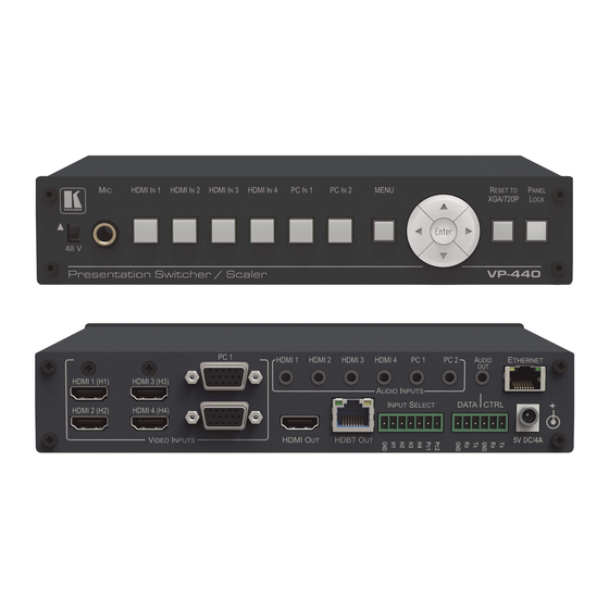
Defining the VP-440 Presentation Switcher/Scaler This section defines the VP-440. Figure 1: VP-440 Presentation Switcher/Scaler Front Panel Feature Function / 48 V Move up (48V) to select a condenser type microphone; down to select a dynamic type microphone. (We recommend... -
Page 12: Figure 2: Vp-440 Presentation Switcher/Scaler Rear Panel
Figure 2: VP-440 Presentation Switcher/Scaler Rear Panel Feature Function VIDEO INPUT HDMI Connect to the HDMI source (from 1 to 4) Connectors PC 15-pin HD Connect to the computer graphics source (from 1 to 2) AUDIO INPUT HDMI Connect to the analog audio HDMI source (from 1 to 4) -
Page 13: Connecting The Vp-440
(H1) VIDEO INPUT connector (from 1 to 4). Alternatively, you can connect the DVI connector on the DVD player to the HDMI connector on the VP-440 via a DVI-HDMI adapter. When using this adapter, you can connect the audio signal via the terminal block connector 2. -
Page 14: Figure 3: Connecting The Vp-440 Presentation Switcher / Scaler
10. Connect the INPUT SELECT 7-pin terminal block contact-closure remote- control pins to select an input by momentarily pressing the switch. 11. Connect the ETHERNET port, see Section 5.4 Figure 3: Connecting the VP-440 Presentation Switcher / Scaler VP-440 - Connecting the VP-440... -
Page 15: Microphone Pinout
Microphone Pinout The microphone 6.3mm jack pinout for a condenser microphone. Figure 4: Condenser Microphone Pinout The microphone 6.3mm jack pinout for a Dynamic microphone. Figure 5: Dynamic Microphone Pinout VP-440 - Connecting the VP-440... -
Page 16: Wiring The Tp Line Out Rj-45 Connector
This section defines the TP pinout, using a straight pin-to-pin cable with RJ-45 connectors. Figure 6: TP PINOUT EIA /TIA 568B Wire Color Orange / White Orange Green / White Blue Blue / White Green Brown / White Brown VP-440 - Connecting the VP-440... -
Page 17: Controlling The Vp-440
FINETUNE menu (see Section 5.2.1). Using the OSD Menu The control buttons let you control the VP-440 via the OSD menu. Press the: MENU button to enter the menu The default timeout is set to 10 seconds ... -
Page 18: The Main Menu
AUTOMATIC: the embedded audio on the HDMI input is selected for an HDMI signal, or the analog audio input is selected if the input is not HDMI (for example, for a DVI input signal) EMBEDDED: the embedded audio in the HDMI signal is selected VP-440 - Controlling the VP-440... - Page 19 Set the OSD background between 100 (transparent) and 0 (opaque) DISPLAY Select the information shown on the screen during operation: INFO: the information is shown for 10 seconds ON: the information is shown permanently OFF: the information is not shown VP-440 - Controlling the VP-440...
- Page 20 Lock the MENU (and navigation) front panel buttons only ALL & SAVE Lock all the front panel buttons. The lock status is saved when the VP-440 is powered down MENU ONLY AND Lock the MENU (and navigation) front panel buttons SAVE only.
-
Page 21: Connecting To The Vp-440 Via Rs-232
RS-232 CTRL (Tx, Rx, GND) to control the VP-440 To connect to the VP-440 via RS-232 connect the RS-232 Terminal block connector on the product to the RS-232 9-pin D-sub port on your PC/controlled device: Figure 8: RS-232 Pinout... -
Page 22: Operating Via Ethernet
5.4.1 Connecting the Ethernet Port Directly to a PC You can connect the Ethernet port of the VP-440 directly to the Ethernet port on your PC using a crossover cable with RJ-45 connectors. This type of connection is recommended for identifying the VP-440 with the factory configured default IP address. -
Page 23: Figure 9: Local Area Connection Properties Window
4. Highlight either Internet Protocol Version 6 (TCP/IPv6) or Internet Protocol Version 4 (TCP/IPv4) depending on the requirements of your IT system. 5. Click Properties. The Internet Protocol Properties window relevant to your IT system appears as shown in Figure 10 Figure VP-440 - Controlling the VP-440... -
Page 24: Figure 10: Internet Protocol Version 4 Properties Window
Figure 10: Internet Protocol Version 4 Properties Window Figure 11: Internet Protocol Version 6 Properties Window VP-440 - Controlling the VP-440... -
Page 25: Figure 12: Internet Protocol Properties Window
8. Click Close. 5.4.2 Connecting the Ethernet Port via a Network Hub or Switch You can connect the Ethernet port of the VP-440 to the Ethernet port on a network hub or using a straight-through cable with RJ-45 connectors. 5.4.3... -
Page 26: Controlling The Vp-440 Via The Remote Terminal Block Connector
Controlling the VP-440 via the REMOTE Terminal Block Connector The REMOTE terminal block connectors include six input pins (H1 to H4 and PC1 to PC2) and a G pin for selecting an input. The contact closure remote control pins operate in a similar way to the INPUT... -
Page 27: Using The Embedded Web Pages
Using the Embedded Web Pages The VP-440 can be operated remotely using the embedded Web pages. The Web pages are accessed using a Web browser and an Ethernet connection. Before attempting to connect: Perform the procedures in Section 5.4. -
Page 28: The Input Select Page
The model name, FW version and IP number appear on the lower left side of the main page. The lower part of the screen lets you save the settings and upload a saved setting. VP-440 - Using the Embedded Web Pages... -
Page 29: Figure 14: The Input Select Page
Figure 14: The Input Select Page Click the power icon on the top right-hand side to toggle between normal operation and standby mode. When in standby mode, the icon appears dim: Figure 15: The VP-440 Standby Mode VP-440 - Using the Embedded Web Pages... -
Page 30: Figure 16: The Input Select Page - Mixer On/Off
Web page and save it, and also set the audio source and its volume. When selecting a PC input you can change the inputs’ name and set the input volume. Upon completion, save the changes ( ) and click the exit icon ( VP-440 - Using the Embedded Web Pages... -
Page 31: The Device Settings Page
18) lets you upgrade the firmware and set the Ethernet parameters. Figure 18: The Device Settings Page Any change in the device settings requires confirmation, as illustrated in the example Figure Figure 19: The Device Settings Page – Static IP Confirmation VP-440 - Using the Embedded Web Pages... -
Page 32: Figure 20: The Device Settings Page - Uploading The New Firmware File
4. After restarting the system you need to re-enter the IP address of the device and refresh the Web page. 5. Make sure that the new version appears on the Web page lower left side: Figure 22: The Device Settings Page – New Firmware Updated VP-440 - Using the Embedded Web Pages... -
Page 33: The Output Settings Page
The output settings include the Resolution and Size, the picture settings, the Finetune items (enabled for VGA inputs) which can be auto adjusted or set separately, and the Finetune reset button (for resetting the finetune parameters to their default values). VP-440 - Using the Embedded Web Pages... -
Page 34: The Hdcp Page
The HDCP page lets you set the HDCP on the output (follow input or follow output) and the HDCP status for each of the HDMI inputs. Figure 24 shows the HDCP page: Figure 24: The HDCP Page VP-440 - Using the Embedded Web Pages... -
Page 35: The Edid Page
(HDMI or VGA) to one or more selected inputs. Figure 25: The EDID Page Figure 26 shows how to select a resolution from the list and select one or more inputs. To copy, click the Copy button: VP-440 - Using the Embedded Web Pages... -
Page 36: Figure 26: The Edid Page - Copying A Resolution
After clicking the Copy button, the EDID page shows the copy EDID results: Figure 27: The EDID Page –The Copy EDID Results Click Close to complete the EDID procedure. VP-440 - Using the Embedded Web Pages... -
Page 37: The Audio Settings Page
Set the Lip sync, the audio source (automatic, analog or embedded for the HDMI inputs) and volume level for each input. For Mic Settings, see the Main Menu in Section 5.2.1. Figure 28: The Audio Settings Page VP-440 - Using the Embedded Web Pages... -
Page 38: The Advanced Page
(mute follows freeze and mute follows blank). Figure 29: The Advanced Page The About Page The VP-440 About page lets you view the Web page version and Kramer Electronics Ltd details. Figure 30: The About Page VP-440 - Using the Embedded Web Pages... -
Page 39: Technical Specifications
21.5cm x 16.3cm x 4.4cm (8.5" x 6.42" x 1.73"), W, D, H WEIGHT: 1.53kg (3.37lbs) approx. INCLUDED ACCESSORIES: Power supply RK-1 rack adapter, Kramer BC−HDKat6a cable OPTIONS: Specifications are subject to change without notice at http://www.kramerelectronics.com VP-440 - Technical Specifications... -
Page 40: Default Communication Parameters
1080P (50/60Hz) 1080P (24/25/30Hz) 640x480 (60/72/75/85Hz) 800x600 (56/60/72/75Hz) 1024x768 (60/70/75Hz) 1280x1024 (60/75Hz) 1280x720 60Hz 1920x1080 60Hz 1280x960 60Hz 1600x1200 60Hz 1280x800 60Hz 1440x900 60Hz 1366x768 60Hz 1400x1050 60Hz 1600x900 RB 60Hz 1680x1050 RB 60Hz 1920x1200 RB 60Hz VP-440 - Technical Specifications... -
Page 41: Output Resolutions
640x480 60Hz 800x600 60Hz 1024x768 60Hz 1280x800 60Hz 1360x768 60Hz 1440x900 60Hz 1280x1024 60Hz 1400x1050 60Hz 1680x1050 60Hz 1600x1200 60Hz 1920x1200 RB 60Hz 1280x720 60Hz 1920x1080 60Hz 720x480P 60Hz 720x576P (50Hz) 1280x720P (50/60Hz) 1920x1080I (50/60Hz) 1920x1080P (50/60Hz) VP-440 - Technical Specifications... -
Page 42: The Rs-232/Ethernet (Udp) Communication Protocol
The RS-232/Ethernet (UDP) Communication Protocol The VP-440 can be operated using serial commands from a PC, remote controller, or touch screen. The unit communicates using the default Kramer Protocol 3000. Kramer Protocol 3000 syntax (see Section 8.1) Kramer Protocol 3000 commands (see Section 8.2) - Page 43 Message starting character '#' – For host command/query '~' – For machine response Device address (Optional, for K-NET) K-NET Device ID followed by '@' Query sign '?' follows some commands to define a query request. VP-440 - The RS-232/Ethernet (UDP) Communication Protocol...
- Page 44 You can directly enter all commands using a terminal with ASCII communications software, such as HyperTerminal, Hercules, etc. Connect the terminal to the serial or Ethernet port on the Kramer device. To enter CR press the Enter key. ( LF is also sent but is ignored by command parser).
-
Page 45: Kramer Protocol 3000 - Command List
#SCLR-AS? Get auto-sync features #IMAGE-PROP Set the image size #IMAGE-PROP? Get the image size #SCLR-PCAUTO Set PC auto sync of scaler #SCLR-AUDIO-DELAY Set the scaler audio delay #SCLR-AUDIO-DELAY? Get the scaler audio delay VP-440 - The RS-232/Ethernet (UDP) Communication Protocol... -
Page 46: Kramer Protocol 3000 - Detailed Commands
720p @60Hz 1360x768 @60Hz 1080i @60Hz 1280x720 @60Hz 1080p @60Hz 1280x800 @60Hz 576p @50Hz 1280x1024 @60Hz 720p @50Hz 1440x900 @60Hz 1080i @50Hz 1400x1050 @60Hz 1080p @50Hz NATIVE OUT1 1680x1050 @60Hz NATIVE OUT2 1600x1200 @60Hz VP-440 - The RS-232/Ethernet (UDP) Communication Protocol... - Page 47 FACTORY End User Get: Description Syntax Set: Reset device to factory defaults configuration #FACTORY␍ Get: Response ~nn@FACTORY␠OK␍␊ Notes This command deletes all user data from the device. The deletion can take some time. VP-440 - The RS-232/Ethernet (UDP) Communication Protocol...
- Page 48 To avoid locking the port due to a USB bug in Windows, disconnect USB connections immediately after running this command. If the port was locked, disconnect and reconnect the cable to reopen the port. VP-440 - The RS-232/Ethernet (UDP) Communication Protocol...
- Page 49 Command – NET-MAC? Command Name Permission Transparency Set: NET-MAC? Get: End User Description Syntax Set: Get: Get MAC address #NET-MAC?␍ Response ~nn@NET-MAC␠mac_address␍␊ Parameters mac_address – Unique MAC address. Format: XX-XX-XX-XX-XX-XX where X is hex digit. VP-440 - The RS-232/Ethernet (UDP) Communication Protocol...
- Page 50 Get: ~nn@ NET-GATE ␠ ip_address ␍␊ Parameters P1 (valid IP address)=xxx.xxx.xxx.xxx Notes A network gateway connects the device via another network and maybe over the Internet. Be careful of security problems. For proper settings consult your network administrator VP-440 - The RS-232/Ethernet (UDP) Communication Protocol...
- Page 51 To connect with a randomly assigned IP by DHCP, specify the device DNS name (if available) using the command “NAME”. You can also get an assigned IP by direct connection to USB or RS-232 protocol port if available. For proper settings consult your network administrator. VP-440 - The RS-232/Ethernet (UDP) Communication Protocol...
- Page 52 Response is sent after every change in output HPD status ON to OFF Response is sent after every change in output HPD status OFF to ON and ALL parameters (new EDID, etc.) are stable and valid VP-440 - The RS-232/Ethernet (UDP) Communication Protocol...
- Page 53 (button press, device menu and similar) or genlock status changed Notes Set HDCP working mode on device input : – HDCP_ON [default] HDCP supported HDCP not supported – HDCP OFF HDCP support changes following detected sink – MIRROR OUTPUT VP-440 - The RS-232/Ethernet (UDP) Communication Protocol...
- Page 54 Set enable/disable video on output #VMUTE␠P1, P2␍ #VMUTE?␠P1␠ ␍ Get: Get video on output status Response Set / Get: ~ nn@ VMUTE␠ P1,P2␍␊ Parameters P1 (Scaler number) – 1=Scaler P2 (Off/On) – 0=Off; 1=On VP-440 - The RS-232/Ethernet (UDP) Communication Protocol...
- Page 55 Set: MUTE End User Public MUTE? Get: End User Public Description Syntax Set: Set audio mute #MUTE␠channel,mute_mode␍ Get: Get audio mute #MUTE?␠channel␍ Response ~nn@MUTE␠channel, mute_mode␍␊ Parameters channel – Scaler=1 mute_mode - 0=Off; 1=ON VP-440 - The RS-232/Ethernet (UDP) Communication Protocol...
- Page 56 After execution, response is sent to all com ports if CMD-NAME was set any other external control device (button press, device menu and similar) or genlock status was changed Notes Sets the image properties of the selected scaler VP-440 - The RS-232/Ethernet (UDP) Communication Protocol...
- Page 57 After execution, response is sent to all com ports if CMD-NAME was set any other external control device (button press, device menu and similar) or genlock status was changed Notes Sets the audio delay for the selected audio output VP-440 - The RS-232/Ethernet (UDP) Communication Protocol...
- Page 58 End User Public Description Syntax Set: Set audio talkover mode status #TLK␠channel,talkover_mode␍ Get: Get audio talkover mode status #TLK?channel,␍ Response ~nn@TLK␠channel,talkover_mode␍␊ Parameters channel - output number talkover_mode – 0=OFF; 1=Mixer; 2=Talkover; 3=Mic only VP-440 - The RS-232/Ethernet (UDP) Communication Protocol...
- Page 59 End User Public Description Syntax Set: # STANDBY ␠ on_off ␍ Set Standby mode Get: # STANDBY? ␍ Get Standby mode status Response ~ nn @STANDBY ␠ value ␍␊ Parameters on_off – 0=Off; 1=On VP-440 - The RS-232/Ethernet (UDP) Communication Protocol...
-
Page 61: Safety Warning
SAFETY WARNING Disconnect the unit from the power supply before opening and servicing For the latest information on our products and a list of Kramer distributors, visit our Web site where updates to this user manual may be found. We welcome your questions, comments, and feedback.
Need help?
Do you have a question about the VP-440 and is the answer not in the manual?
Questions and answers