Table of Contents
Advertisement
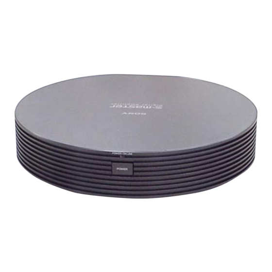
SERVICE MANUAL
Ver. 1.0 2005.05
TA-WR2 is the surround amplifier section in
DAV-FX100W/DZ700FW.
Sony Corporation
9-879-677-01
Audio Group
2005E1678-1
Published by Sony Engineering Corporation
© 2005.05
SPECIFICATIONS
Power requirements
220 – 240 V AC, 50/60 Hz (AEP, UK, RU)
120V AC, 60 Hz (US, CND)
Power consumption
50 W
×
Dimensions (approx.)
260
260.5
(w/h/d)
Mass (approx.)
1.45 kg
Design and specifications are subject to change
without notice.
TA-WR2
Canadian Model
×
58 mm
•
Abbreviation
RU
: Russian model
CND : Canadian model
SURROUND AMPLIFIER
US Model
AEP Model
UK Model
Advertisement
Table of Contents

Related Manuals for Sony TA-WR2


Summary of Contents for Sony TA-WR2
-
Page 1: Service Manual
SERVICE MANUAL US Model Canadian Model Ver. 1.0 2005.05 AEP Model UK Model TA-WR2 is the surround amplifier section in DAV-FX100W/DZ700FW. SPECIFICATIONS Power requirements 220 – 240 V AC, 50/60 Hz (AEP, UK, RU) 120V AC, 60 Hz (US, CND) -
Page 2: Table Of Contents
PIÈCES SONT CRITIQUES POUR LA SÉCURITÉ DE 3-2. RX Board, DIAT POWER Board Section ....... 18 FONCTIONNEMENT. NE REMPLACER CES COM- POSANTS QUE PAR DES PIÈCES SONY DONT LES NUMÉROS SONT ELECTRICAL PARTS LIST ........19 DONNÉS DANS CE MANUEL OU DANS LES SUPPLÉMENTS... -
Page 3: General
TA-WR2 SECTION 1 GENERAL This section is extracted from instruction manual. Surround amplifier POWER/ON LINE POWER Front panel Rear panel SPEAKER DIR-R2 SURROUND L SURROUND R A POWER/ON LINE indicator (33) C DIR-R2 jack (15) B POWER (33) D SPEAKER jacks (15) -
Page 4: Diagrams
TA-WR2 SECTION 2 DIAGRAMS • Note for Printed Wiring Boards and Schematic Diagrams Note on Printed Wiring Boards: Note on Schematic Diagrams: • X : parts extracted from the component side. • All capacitors are in µF unless otherwise noted. (p: pF) •... -
Page 5: Block Diagram
TA-WR2 2-1. BLOCK DIAGRAM IC102 IC109 IC110 IC111 RF DEMODULATOR AND GATE STREAM PROCESSOR POWER AMP A/D CONVERTER L101 T100 J100 DATA 10 ADVIN 2 PWMBP DAOUT DATA OUTL1 OUT B REAR RCH+ DIR-R2 OUT B REAR RCH- REAR LCH+... -
Page 6: Printed Wiring Board - Diat Power Section
TA-WR2 2-2. PRINTED WIRING BOARD — DIAT POWER SECTION — :Uses unleaded solder. • Semiconductor Location Ref. No. Location D901 D902 D904 D905 D906 D907 AEP, UK, RU D908 D909 AEP, UK, RU D910 RX BOARD D911 D913 CN102 D914... -
Page 7: Schematic Diagram - Diat Power Section
TA-WR2 • See page 11 for IC Block Diagrams. 2-3. SCHEMATIC DIAGRAM — DIAT POWER SECTION — S901 CNP901 F901 CN901 CN903 T3.15AL/ R903 D911 PC902 PC123Y22JO0F R917 R922 AEP, UK, RU FH901 250V FH902 10EDB60-TA1B2 C901 R902 C904 C915... -
Page 8: Printed Wiring Board - Rx Board
TA-WR2 2-4. PRINTED WIRING BOARD — RX BOARD — :Uses unleaded solder. SURROUND L SURROUND R DIR-R2 • Semiconductor Location Ref. No. Location D100 D102 D103 D104 D105 D106 D107 D115 IC101 IC102 IC103 DIAT POWER IC104 BOARD IC105 CN904... -
Page 9: Schematic Diagram - Rx Board (1/2)
TA-WR2 • See page 12,14 for IC Block Diagrams. • See page 4 for Waveforms. • See page 15 for IC Pin Function Description. 2-5. SCHEMATIC DIAGRAM — RX BOARD (1/2) — D100 CN101 SPR-54MVWF EB103 R125 R100 EARTH PLATE... -
Page 10: Schematic Diagram - Rx Board (2/2)
TA-WR2 • See page 13,14 for IC Block Diagrams. • See page 4 for Waveform. 2-6. SCHEMATIC DIAGRAM — RX BOARD (2/2) — Q105 2SA1235TP-1EF Q106 2SA1235TP-1EF R153 C165 R154 100k 100k C166 TP26 R156 100k Q109 2SA1235TP-1EF Q108 R155... -
Page 11: Ic Block Diagrams
TA-WR2 • IC Block Diagrams – DIAT POWER Board – IC901 STR-W6765N (AEP, UK, RU) DRIVE REGULATOR REGULATOR PROTECTION START/STOP & ICONST – LATCH BURST DELAY BURST CONTROL NC 2 S/GND 3 VCC 4 SS/OLP 5 – SOFT START FB 6 –... - Page 12 TA-WR2 – RX Board – IC101 XC62HR1502MR VOUT CURRENT LIMIT – OUTPUT REFERENCE CONTROL VOLTAGE IC102 CXD4017R 63 62 61 60 59 58 57 56 53 52 51 50 49 MST 1 TEST4 BUFFER XSM 2 TEST3 SMCK 3 TEST2...
- Page 13 TA-WR2 IC110, 112 CXD9775M GVDD B GVDD GVDD B BST B DVDD DREG DREG GND 1 PVDD B GATE PWM BP 2 PVDD B RECEIVER DRIVE OUT B TIMING GND 3 OUT B CONTROL DGND & PROTECTION RESET 4 GATE...
- Page 14 TA-WR2 IC113 TK11118CSCL-G IC114 SN74AHC1GU04DCKR 5 VCC OVER HEAT & OVER CURRENT PROTECTION CONTROL CIRCUIT BANDGAP REFERENCE...
- Page 15 TA-WR2 • IC Pin Function Description RX BOARD IC107 MB89537APFM-G-654-BNDE1 (SYSTEM CONTROLLER) Pin No. Pin Name Description — Not used MOD2 Setting terminal for the CPU operation mode Fixed at “L” in this set 3, 4 — Not used MODEL...
- Page 16 TA-WR2 Pin No. Pin Name Description — Power supply terminal (+3.3V) MAIN_OFF Power off control signal output to the power control “H”: power off V_CONT Voltage control PWM signal output to the shunt regulator DAMP_LATCH Latch control signal output to the stream processor...
-
Page 17: Exploded Views
TA-WR2 SECTION 3 EXPLODED VIEWS NOTE: • -XX and -X mean standardized parts, so they • The mechanical parts with no reference The components identified by mark 0 or may have some difference from the original number in the exploded views are not supplied. -
Page 18: Rx Board, Diat Power Board Section
TA-WR2 3-2. RX BOARD, DIAT POWER BOARD SECTION supplied F901 supplied supplied supplied supplied supplied Ref. No. Part No. Description Remark Ref. No. Part No. Description Remark A-1111-677-A RX BOARD, COMPLETE 4-240-812-01 HOLDER, WIRE A-1111-680-A DIAT POWER BOARD, COMPLETE (AEP, UK, RU) -
Page 19: Electrical Parts List
TA-WR2 SECTION 4 DIAT POWER ELECTRICAL PARTS LIST NOTE: • Due to standardization, replacements in the • -XX and -X mean standardized parts, so they When indicating parts by reference number, parts list may be different from the parts may have some difference from the original please include the board name. - Page 20 TA-WR2 DIAT POWER Ref. No. Part No. Description Remark Ref. No. Part No. Description Remark L904 1-414-398-11 INDUCTOR 10uH 0 R926 1-216-833-11 METAL CHIP 1/10W R931 1-218-726-11 METAL CHIP 0.5% 1/10W < LINE FILTER > R932 1-216-864-11 SHORT CHIP 0 LF901...
- Page 21 TA-WR2 Ref. No. Part No. Description Remark Ref. No. Part No. Description Remark C193 1-163-035-00 CERAMIC CHIP 0.047uF C131 1-125-837-91 CERAMIC CHIP 6.3V C194 1-162-966-11 CERAMIC CHIP 0.0022uF 10% C132 1-125-837-91 CERAMIC CHIP 6.3V C195 1-164-156-11 CERAMIC CHIP 0.1uF C133 1-107-826-11 CERAMIC CHIP 0.1uF...
- Page 22 TA-WR2 Ref. No. Part No. Description Remark Ref. No. Part No. Description Remark < CONNECTOR > L105 1-469-525-91 INDUCTOR 10uH CN101 1-784-366-21 CONNECTOR, FFC/FPC 7P L106 1-469-525-91 INDUCTOR 10uH CN102 1-691-768-11 PLUG (MICRO CONNECTOR) 6P L107 1-469-525-91 INDUCTOR 10uH CN103...
- Page 23 TA-WR2 Ref. No. Part No. Description Remark Ref. No. Part No. Description Remark R125 1-216-810-11 METAL CHIP 1/10W R185 1-216-864-11 SHORT CHIP R126 1-216-821-11 METAL CHIP 1/10W R186 1-216-864-11 SHORT CHIP R187 1-216-864-11 SHORT CHIP R127 1-216-841-11 METAL CHIP 1/10W...
- Page 24 TA-WR2 SWITCH Ref. No. Part No. Description Remark < TRANSFORMER > T100 1-780-281-11 TERMINAL BOARD (SP) (2P) < VIBRATOR > X101 1-795-485-21 VIBRATOR, CRYSTAL 12.288MHz(SMD) X102 1-795-313-21 VIBRATOR, CERAMIC 8MHz X103 1-795-660-21 QUARTZ CRYSTAL UNIT 49.152MHz ************************************************************ SWITCH BOARD ************* <...
- Page 25 TA-WR2 MEMO...
-
Page 26: Revision History
TA-WR2 REVISION HISTORY Clicking the version allows you to jump to the revised page. Also, clicking the version at the upper right on the revised page allows you to jump to the next revised page. Ver. Date Description of Revision...
Need help?
Do you have a question about the TA-WR2 and is the answer not in the manual?
Questions and answers