Table of Contents
Advertisement
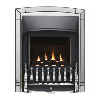
INSTALLER AND OWNER GUIDE
Model 541
ROOM SEALED RADIANT / CONVECTOR
GAS FIRE
Fitted with one of the following fascia.
Camden, Seattle, Sonnet
Ultimate.
(GC No. 32-032-64)
We trust that this guide gives
sufficient details to enable this
appliance to be installed and
maintained satisfactorily. However, if
further information is required, our
Valor Fires Technical Helpline will
be pleased to help.
Telephone 0844 8711 565 (National
call rates apply in the United
Kingdom).
In the Republic of Ireland
Telephone 0044 844 8711 565.
INSTALLER: Please leave this guide with the
©
Baxi Heating U.K. Limited 2008.
5133756/01
or
owner
Advertisement
Table of Contents

Subscribe to Our Youtube Channel
Related Manuals for Valor Fires 541 Camden


Summary of Contents for Valor Fires 541 Camden
- Page 1 However, if further information is required, our Valor Fires Technical Helpline will be pleased to help. Telephone 0844 8711 565 (National call rates apply in the United Kingdom).
- Page 2 Warning: Any person who does any unauthorised act in relation to a copyright work may be liable to criminal prosecution and civil claims for damages. Valor Fires, Erdington, Birmingham B24 9QP www.firesandstoves.co.uk Because our policy is one of constant development and improvement, details may vary slightly from those given in this publication ©...
- Page 3 Careful Installation Valor Fires is a CORGI registered company. All our gas fires must be installed by a competent CORGI Registered Installer in accordance with our Installer Guide and should not be fitted directly on to a carpet.
- Page 4 INSTALLER GUIDE INSTALLER GUIDE FOR OWNER GUIDE SEE PAGES 38 TO 51 © Baxi Heating U.K. Limited 2008. Page 4...
-
Page 5: Table Of Contents
INSTALLER GUIDE CONTENTS Section Heading Page INSTALLER GUIDE 4 - 37 OWNER GUIDE 38 - 51 1. SAFETY 2. APPLIANCE DATA 3. LIST OF AVAILABLE KITS 4. APPLIANCE AND RECESS DIMENSIONS 5. GENERAL INSTALLATION REQUIREMENTS 6. UNPACKING AND PRELIMINARY CHECKS 7. -
Page 6: Installer Guide
INSTALLER GUIDE 1. SAFETY Installer Before continuing any further with the installation of this appliance please read the following guide to manual handling: The approximate lifting weight (kg) of this appliance is as below: Model Heat Engine Fascia Fire front Combined Weight inc. -
Page 7: Appliance Data
INSTALLER GUIDE 2. APPLIANCE DATA Befre continuing with the installation of this appliance please complete the information on the last pages of this guide. The appliance data label is located on a plate at the base of the fire. This can be seen by removing the lower front casting / fire front. -
Page 8: List Of Available Kits
INSTALLER GUIDE Natural Inlet pressure 20mbar Input - Max. (Gross) 3.65kW (12,454 Btu/h) Input - Min. (Gross) 1.5kW (5,118 Btu/h) Inlet pressure (Cold) 20.0 ± 1.0mbar (8.0 ± 0.4in w.g.) Gas connection 8mm pipe Main burner Simplex aerated Burner injector Cat. -
Page 9: Appliance And Recess Dimensions
INSTALLER GUIDE 4. APPLIANCE AND RECESS DIMENSIONS This appliance must not be recessed into a combustible wall. Model Description Ultimate & Camden & Sonnet Seattle Appliance height (mm) Appliance width (mm) Appliance depth into room (mm) Minimum mandatory clearance to combustible surfaces projecting beyond the front of appliance (mm). -
Page 10: General Installation Requirements
A 2in rebate surround in conjunction with the Valor Fires 3in. spacer kit Part No 0595131. Where the surround is mounted to a combustible wall make sure that there is no combustible material or combustible cladding in the area indicated on the wall- fixing template. - Page 11 INSTALLER GUIDE Under no circumstances is the fire to be recessed into Timber frame constructions. For timber framed installations see section 8. The installation must be in accordance with this guide. For the user’s protection, in the United Kingdom it is the law that all gas appliances are installed by competent persons in accordance with the current edition of the Gas Safety (Installation and Use) Regulations.
- Page 12 INSTALLER GUIDE The minimum height from the base of the fire to the underside of any shelf made from wood or other combustible materials is as follows:- • For a shelf up to 150mm deep Minimum height = 780mm. • For a shelf deeper than 150mm 780mm + 12.5mm for every 25mm depth over 150mm.
- Page 13 INSTALLER GUIDE For installations that are not elevated. This appliance does not require a non-combustible hearth. It can be installed on any hard surface. This surface should be level and sufficiently flat to enable the bottom of the fascia / fire front / castings to be aligned horizontally. Any unevenness (Uneven tiles, Cotswold stone etc.) should be rectified.
- Page 14 INSTALLER GUIDE 5.15 If the fire is to be fitted against a wall with combustible cladding, the cladding must be removed from the area shown in figure 3. 5.16 Minimum allowable distances from the terminal are shown in figures 4 and 5. Figure 3.
- Page 15 INSTALLER GUIDE Minimum Terminal position distance (mm) Directly below an opening, air brick, opening window etc. 300mm Above an opening, air brick, opening window etc. 300mm Horizontally to an opening, air brick, opening window etc. 300mm Below gutters, soil pipes or drain pipes. 300mm Below eaves.
-
Page 16: Unpacking And Preliminary Checks
INSTALLER GUIDE exceeding 450mm, such as disused chimneys on external walls. Figure 5. 6. UNPACKING AND PRELIMINARY CHECKS 6.1 Unpacking. 1 Main fire assembly with fascia. 1 Ceramic fuel effect (Packed in the fire). 1 Nut & olive for 8mm inlet pipe. 1 Fire front / fire front casting set. - Page 17 INSTALLER GUIDE 6.2 Appliance disassembly. Fascia removal (See figure 6). Remove the two screws securing the bottom of the fascia to the sides of the convection box. Raise the fascia to allow the retaining lugs at the top to clear the slots in the convection box hood and then lift clear.
-
Page 18: Gas Supply Connection
INSTALLER GUIDE 7. GAS SUPPLY CONNECTION A nut & olive are provided for an 8mm pipe inlet connection to the inlet ‘T’ connector at the bottom front of the appliance. This can be rotated to allow a connection from any direction and includes a valve for isolating the gas supply. The supply pipe must be rigid material. - Page 19 INSTALLER GUIDE 8.2.1 Fitting a lintel. Whenever a lintel is required to support the recess in the inner leaf of a brick/blockwork building, follow the method outlined below (See figure 9). The lintel should be either steel (Catnic) or reinforced precast concrete.
- Page 20 Valor Fires – Ask for Valor Fires part no. 0591221. The insulating sheet can be used to seal the annular gap between the flue unit and the inner leaf sleeve (See section 8.5). Do not permanently fix the insulating sheet to the wall at this stage (See section 9.2).
- Page 21 INSTALLER GUIDE Pierce the template at the centre of the screw fixing holes and the flue hole and mark the positions on the wall. Remove the template. 8.4.1 Core drilling. Drill a pilot hole through the wall. Inspect the hole to ensure that it is in the brickwork and not in mortar.
- Page 22 INSTALLER GUIDE Figure 11. Timber frame wall preparation 8.6 Prepare appliance fixing holes. 8.6.1 Screwing case to wall. Recheck the position of the screw fixing holes relative to the flue hole. Drill the four fixing holes to a minimum depth of 42mm using a suitably sized masonry drill for the wall plugs supplied.
-
Page 23: Flue And Terminal Installation
INSTALLER GUIDE Fit the two eyebolts. 9. FLUE AND TERMINAL INSTALLATION 9.1 Cutting flue to size. For outset appliances with surround or spacer Measure the total wall thickness from the outside surface of the wall to the inside face of the surround or spacer. Deduct 35mm from this measurement to obtain the correct length of flue unit required (See figures 13 &... -
Page 24: Fitting To Wall
INSTALLER GUIDE Figure 14. Flue unit installation - Timber framed building. 9.2 Fitting to wall. Fit the flue tubes firmly over the spigots at the rear of the fire. Make sure that the seam on the flue tube is not at the bottom. Push on until the outer (air) tube just covers the slots in the appliance outer spigot (See figure 15). -
Page 25: Fitting The Terminal Guard
INSTALLER GUIDE through the wall. Pull the cables taut. Timber frame building with combustible outer leaf (e.g. shiplap boarding): A metal or other non-combustible end plate must be fitted on the outside of the wall. The plate must be concentric with the flue and at least 254mm (10in) square or diameter (See figure 14). -
Page 26: Ceramic Coals Installation
INSTALLER GUIDE 11. CERAMIC COALS INSTALLATION This section is for models supplied with a ‘Coal’ fuel effect only. For ‘Pebble fuel effect’ see section 12 The ceramic fuel effect may cause staining / discolouration to decorative surfaces. It is therefore advisable to protect decorative surfaces. - Page 27 INSTALLER GUIDE 3. Hold coal ‘B’ upright with the arrow pointing to the top. Locate coal ‘B’ as shown in figure 19. Figure 19. 4. Hold coal ‘C’ upright with the arrow pointing to the top. Locate coal ‘C’ as shown in figure 20.
-
Page 28: Ceramic Pebbles Installation
INSTALLER GUIDE 12. CERAMIC PEBBLES INSTALLATION This section is for models supplied with a ‘Pebble’ fuel effect only. For ‘Coal fuel effect’ see section 11. The ceramic fuel effect may cause staining / discolouration to decorative surfaces. It is therefore advisable to protect decorative surfaces. - Page 29 INSTALLER GUIDE 3. Hold pebble ‘B’ upright with the arrow pointing to the top. Locate pebble ‘B’ as shown in figure 25. Figure 25. 4. Hold pebble ‘C’ upright with the arrow pointing to the top. Locate pebble ‘C’ as shown in figure 26.
-
Page 30: Window Fitting
INSTALLER GUIDE 13. WINDOW FITTING Fitting the window. Locate the channel at the top of the window over the top of the firebox opening. Refit the three spring loaded screws and bushes. The wide part of the bushes should be in contact with the window frame. Tighten sufficiently to seal the firebox. Pull the bottom of the window forward and release to check that the window opens slightly and returns in the event of a delayed ignition explosion. -
Page 31: Checking Inlet Pressure
INSTALLER GUIDE kept at any position enabling the customer to use the right hand control only to ignite the burner at the set flame height. After checking turn the right hand knob to off. Depress the control knob partially at the •... -
Page 32: Fascia Fitting
INSTALLER GUIDE 15. FASCIA FITTING If you have not done so already complete the information on the last pages of this guide. Remove any protective film from the fascia. Locate the two lugs at the top of the fascia in the slots in the convection box hood. -
Page 33: Final Review
INSTALLER GUIDE 16. FINAL REVIEW Recheck the pilot ignition and operation of the fire through the range of settings. Visually inspect the appliance. Clean off any marks incurred during installation. Advise the customer to read their owner guide before operating the fire and to always follow the advice in the section headed “Cleaning Your Fire”. -
Page 34: Servicing & Parts Replacement
INSTALLER GUIDE 17. SERVICING & PARTS REPLACEMENT Always turn off the gas and allow the appliance to cool completely before commencing any servicing. (The inlet ‘T’ connector on this appliance incorporates an isolating valve) Always test for gas soundness after refitting the appliance. This product uses a fuel effect, a burner compartment rear wall and gaskets containing Refractory Ceramic Fibres (RCF), which are man-made vitreous silicate fibres. -
Page 35: To Remove Window Unit
INSTALLER GUIDE clear the slots in the convection box hood and then lift clear (See figure 34). 17.2 To remove window unit. Remove the fascia (See section 17.1). Unscrew and remove the three spring-loaded window- fixing screws and bushes from the base of the window frame (See figure 35). -
Page 36: To Remove The Burner From The Burner Module
INSTALLER GUIDE 17.5 To remove the burner from the burner module. Remove the complete burner module as in section 17.4. Support the injector elbow and unscrew the pipe nut from its base. The burner bracket is secured to the front cover by four screws. Remove these screws. -
Page 37: To Remove The Gas Valve
INSTALLER GUIDE 17.8 To remove the gas valve. Remove the complete burner module as in section 17.4 Remove the electrode lead at the pilot. Do this by holding the lead as close to the electrode as possible. This will limit the possibility of damaging the lead connection. -
Page 38: Owner Guide
OWNER GUIDE OWNER GUIDE FOR WARRANTY AND SERVICE INFORMATION SEE PAGES 45 TO 51 © Baxi Heating U.K. Limited 2008. Page 38... - Page 39 OWNER GUIDE CONTENTS Section Heading Page SAFETY APPLIANCE DIMENSIONS GAS CONSUMPTION OPERATING YOUR FIRE To light the pilot. To light the main burner. To Turn off the main burner only. To turn off the main burner and pilot. CLEANING YOUR FIRE MAINTENANCE WARRANTY AND SERVICE This gas fire is designed to meet the most stringent quality, performance and safety...
- Page 40 OWNER GUIDE SAFETY IF YOU SMELL GAS DON’T SMOKE. EXTINGUISH ALL NAKED FLAMES. DON’T TURN ELECTRICAL SWITCHES ON OR OFF. TURN OFF THE GAS SUPPLY AT THE METER. OPEN DOORS AND WINDOWS TO GET RID OF THE GAS. IMMEDIATELY CALL THE GAS EMERGENCY SERVICE FROM A NEIGHBOURS PHONE - SEE YOUR LOCAL TELEPHONE DIRECTORY.
- Page 41 OWNER GUIDE is a heating appliance and certain parts of its surface will become hot. Do wait three minutes before attempting to relight if the fire is switched off or the flames are extinguished for any reason. Your fire is fitted with a safety device which will automatically shut off the gas supply to the fire if, for any reason, the flames go out.
- Page 42 OWNER GUIDE APPLIANCE DIMENSIONS Model Description Ultimate & Camden & Sonnet Seattle Appliance height (mm) Appliance width (mm) Appliance depth into room (mm) Minimum mandatory clearance to combustible surfaces projecting beyond the front of appliance (mm). Recommended clearance to non-combustible surfaces for access purposes (mm).
- Page 43 OWNER GUIDE GAS CONSUMPTION Model 541 Has a maximum natural gas input of 3.65kW (Gross) Has a maximum natural gas output of 2.8kW Has a minimum natural gas input of 1.5kW (Gross) Has a minimum natural gas output of 1.13kW OPERATING YOUR FIRE The pilot may be left alight.
- Page 44 OWNER GUIDE To light the main burner. Partially depress the right control knob and turn to the main burner position marked . The main burner should now light at its low position. The left-hand knob is for burner flame adjustment. Turning it anticlockwise should gradually increase the flame height and heat output.
- Page 45 OWNER GUIDE WARRANTY AND SERVICE Standard Warranty Terms & Conditions The warranty is for 12 months subject to contract. In the United Kingdom servicing can be carried out either by a heateam service engineer or a CORGI registered installer. You must register your fire with heateam, the service division of Baxi Heating UK Limited, either by completing and returning the registration card or calling our free telephone registration line on 0800 032 72 44.
- Page 46 OWNER GUIDE When calling heateam, it would be helpful if you could have the following information to hand:- Fire serial number and fascia code (Located on the information label - See figure 4 on page 51). Date of installation. Your installer name and address details. Fire make and model number.
- Page 47 OWNER GUIDE © Baxi Heating U.K. Limited 2008. Page 47...
- Page 48 OWNER GUIDE Page 48 © Baxi Heating U.K. Limited 2008.
- Page 49 OWNER GUIDE © Baxi Heating U.K. Limited 2008. Page 49...
- Page 50 OWNER GUIDE To be completed by Installer: Installer Details (Block Capitals) Installer Name Corgi Registration Number. Company Name. Company Address Company Telephone number Company Fax number © Baxi Heating U.K. Limited 2008. Page 50...
-
Page 51: Owner Guide
OWNER GUIDE Model Serial number (Can be found on the information label - See figure 4) A LABEL CONTAINING THE SERIAL NUMBER MAY HAVE BEEN PLACED INSIDE THIS BOX. Fascia name (Block Capitals) Fascia code - Can be found close to the information label (Block Capitals) A LABEL CONTAINING THE FASCIA CODE MAY HAVE BEEN PLACED INSIDE THIS BOX. - Page 52 © Baxi Heating U.K. Limited 2008.
Need help?
Do you have a question about the 541 Camden and is the answer not in the manual?
Questions and answers