
Related Manuals for JUKI LK-1900AN


Summary of Contents for JUKI LK-1900AN
- Page 1 Computer-controlled High-speed Bartacking Machine LK-1900AN Series ENGINEER’S MANUAL 40111443 No. E402-00...
- Page 2 PREFACE This Engineer’s Manual is written for the technical personnel who are responsible for the service and maintenance of the machine. The Instruction Manual for these machines intended for the maintenance personnel and operators at an apparel factory contains operating instruction in detail. And this manual describes “Standard Adjust- ment”, “Adjustment Procedures”, “Results of Improper Adjustment”, and other important information which are not covered in the Instruction Manual.
- Page 3 TO ENSURE SAFE USE OF YOUR SEWING MACHINE Adjustment : It means replacement of parts, disassembly, and repair assembly. For the sewing machine, automatic machine and ancillary devices (hereinafter collectively referred to as "machine"), it is inevitable to conduct sewing work near moving parts of the machine. This means that there is always a possibility of unintentionally coming in contact with the moving parts.
- Page 4 JUKI assumes no responsibility for damages or personal injury or death resulting from the use of the machine for any application other than the intended one.
- Page 5 Table and table stand 1. Be sure to use JUKI genuine table and table stand in order to prevent accident that can result in per- sonal injury or death. If it is inevitable to use a table and table stand which are not JUKI genuine ones, select the table and table stand which are able to support the machine weight and reaction force during operation.
- Page 6 7. If the machine cannot be normally operated after repair or adjustment, immediately stop operation and contact JUKI or the distributor in your area for repair in order to prevent accident that can result in per- sonal injury or death.
-
Page 7: Electrical Components
Replacement of parts 1. In prevention of accident caused by unfamiliarity with the machine or electrical-shock accident, be sure to ask an electrical technician of your company or JUKI or distributor in your area for replacement of electrical components. 2. When it is necessary to open the control box containing electrical parts, be sure to turn the power off and wait for five minutes or more before opening the cover in order to prevent accident caused by un- familiarity with the machine or electrical-shock accident. - Page 8 2. In prevention of accident caused by unfamiliarity with the machine or electrical-shock accident, be sure to ask an electrical technician of your company or JUKI or distributor in your area for disassembly/as- sembly of electrical components. 3. When it is necessary to open the control box containing electrical parts, be sure to turn the power off and wait for five minutes or more before opening the cover in order to prevent accident caused by unfa- miliarity with the machine or electrical-shock accident.
- Page 9 22. In order to prevent possible accidents due to a ground fault, the earth cable should be prop- erly grounded. 23. For the control box to be connected to the LK-1900AN Series, use the exclusive control box for the LK-1900AN Series. (If the control box for the LK-1900A Series is connected to the...
- Page 10 Safety devices and warning labels Warning label Thread take-up Warning label (Refer lever cover against pinching The label gives to the the minimum This is a cover This label warns warning precautions to for preventing that fingers or be taken when label on contact between other parts of...
-
Page 11: Table Of Contents
CONTENTS 1. Specifications ..................1 2. Configuration ..................2 (1) Names of main unit ....................2 (2) Names and explanation of switches on the operation panel ......3 3. Standard adjustment ................4 (1) Main shaft connection/disconnection ..............4 (2) Adjustment of the main shaft wheel position ........... 6 (3) Removal of the main shaft motor and coupling .......... - Page 12 4. Sub-class information ................. 52 (1) Models classified by button sizes (LK-1903AN) ..........52 (2) Table of Standard Patterns (LK-1903AN) ............53 5. Memory switches................. 54 (1) Memory switch start and change ..............54 (2) Table of memory switch functions ..............55 6.
-
Page 13: Specifications
17 Lubricating oil JUKI NEW Defrix oil No.2 (equivalent to ISO VG32) (Lubrication system) 18 Grease 1. Penetration No. 2 lithium grease, 2. Templex N2, 3. JUKI Grease A, 4. JUKI Grease B (Caution) 2. 19 Memory medium EEP-ROM (128 Kbyte) EP-ROM (32 Kbyte) 20 Number of stitches that can Max. -
Page 14: Configuration
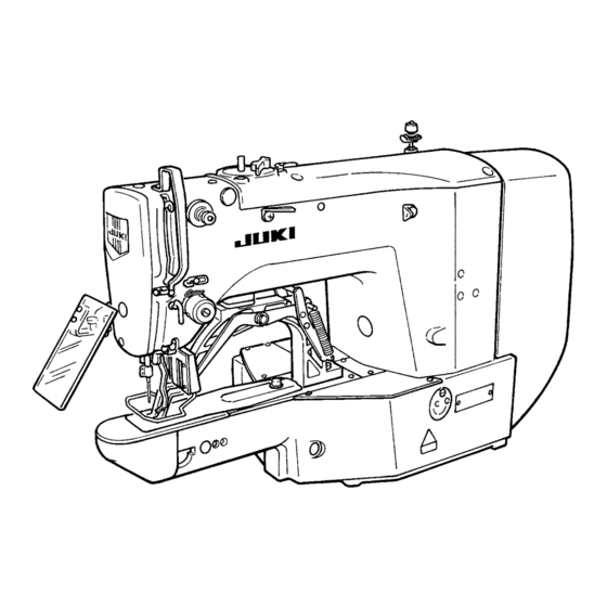
2. Configuration (1) Names of main unit 1 Sewing machine head 2 Work clamp foot 3 Thread stand 4 Operation panel 5 Power switch 6 Control box 7 Pedal switch 8 Power switch (EU Type) – 2 –... -
Page 15: Names And Explanation Of Switches On The Operation Panel
(2) Names and explanation of switches on the operation panel “Ready” key Item selection LED This key changes over the setting state from LEDs of the selected items light up. the panel to the sewing state where the sewing machine actually operates. Pattern No. -
Page 16: Standard Adjustment
3. Standard adjustment (1) Main shaft connection/disconnection Procedures of disassembling Loosen the set screw 2 of the main shaft counterbalance 1 through the screwdriver hole A, then remove the taper screw 3 . Loosen the two set screws 4 (through the screwdriver hole B), and also the two each of 5 and 6 . At that time, loosen the second set screw first. - Page 17 Procedures of assembling Insert the crank rod !5 , balancer !1 , the main shaft wheel @1 , hand pulley gear A !6 , bobbin winder driver wheel !7 , and the main shaft counterbalance 1 in the main shaft 7 in this order, and mount the assembly on the frame.
-
Page 18: Adjustment Of The Main Shaft Wheel Position
(2) Adjustment of the main shaft wheel position Standard adjustment The distance is 3 mm between the measuring plane A of the main shaft wheel 1 and the plane B of the middle bearing bush of the main shaft. – 6 –... - Page 19 Adjustment procedures Results of Improper adjustment Adjust the position of the main shaft wheel 1 and fix it with two set screws 2 . – 7 –...
-
Page 20: Removal Of The Main Shaft Motor And Coupling
(3) Removal of the main shaft motor and coupling Procedures of disassembling Removal of the main shaft motor together with coupling Loosen the two set screws 5 on the main shaft side of the coupling 2 . Then, remove the four motor set screws 4 . - Page 21 Procedures of assembling Mounting of the main shaft motor together with the coupling 1) Tighten the four motor set screws 4 . Then, tighten the two set screws 5 on the main shaft side of the coupling 2 . 2) The cords of the main shaft motor 3 should be positioned in the sidewise direction. Incorporation of the coupling in the main shaft motor 1) Provide a clearance of 0.5 mm between the coupling 2 and the main shaft motor 3 .
-
Page 22: Crank Connecting Rod Connection/Disconnection
(4) Crank connecting rod connection/disconnection Procedures of disassembling Remove the two set screws 1 and four set screws !3 . Then take out the lengthwise feed motor 2 and the crosswise feed motor mounting plate 3 . Loosen the two set screws 4 , two set screws !5 and the two set screws 5 . At that time, the second screws should be loosened first for the set screws 4 , 5 and !5 . - Page 23 Procedures of assembling Mount the main shaft 7 according to "1) Main shaft connection/disconnection." Assemble the crank rod unit !2 . Mount the frame while the oscillator !0 and the oscillator arm !4 is passed through the oscillator shaft Pass the thrust collar !1 through the oscillator shaft 6 . Lightly push the oscillator shaft 6 in the direc- tion of the arrow C and the thrust collar !1 in the direction of the arrow D.
-
Page 24: Crank Balancer Positioning
(5) Crank balancer positioning Standard adjustment [Rotating direction] When the needle bar 3 lowers and the clearance between the needle bar connecting 4 and the needle bar bushing, lower 5 is 5.7 mm (LK-1903AN: 4.6 mm), the two set screws 7 of the crank balancer 6 as- sume the horizontal condition. - Page 25 Adjustment procedures Results of Improper adjustment If the main shaft eccentric cam 8 is not fixed, this adjustment If the angle for fixing the crank should be carried out after defining its position and fixing it. balancer 6 is inadequate, vibra- Loosen the two set screws 7 of the crank balancer 6 .
-
Page 26: Oscillator Gear Positioning
(7) Oscillator gear positioning Standard adjustment When the oscillator is lightly swung by a finger in the direction of the arrow, the oscillator 2 is fixed in the center position of swinging. No. 2 screw No. 1 screw B: 8.5 to 9.0 mm (8) Adjustment of hook oil amount Standard adjustment –... - Page 27 Adjustment procedures Results of Improper adjustment 1. Loosen the two set screws 5 and increase the backlash of the If the position for fixing the oscil- lower shaft gear 3 . lator 2 is inadequate, this can (Caution) If the lower shaft gear 3 has insufficient backlash, also be a cause of the frictional the oscillator 2 does not swing correctly.
-
Page 28: Shuttle Connection/Disconnection And Oil Wick Piping
(9) Shuttle connection/disconnection and oil wick piping Procedures of disassembling Loosen the four set screws 1 . Cut the harness bands 2 and 3 . Remove the set screw 4 and pull the oil tank 5 in the direction of the arrow A. Pull Part B upwards of the two lubrication pipes 6 . - Page 29 Procedures of assembling Pass the two lubrication pipes 6 and the oil drain pipe 7 through the frame, and mount the shuttle !3 . Hold the lubrication pipe 6 with the lubrication pipe holder plate !4 and fix it with the set screw 1 . At that time, make sure not to let the lubrication pipe 6 come in contact with the thread trimmer con- nector rod.
-
Page 30: Hook Adjustment
(11) Hook adjustment Standard adjustment For DP × 5 For DP × 17 0.05 to 0.1 mm – 18 –... - Page 31 Adjustment procedures Results of Improper adjustment Turn the pulley by hand. When needle bar 1 has gone up, adjust so that lower marker line 2 engraved on the needle bar aligns with the bottom end of the needle bar bushing lower 3 . Loosen setscrew 4 in the driver 9 .
-
Page 32: Thread Trimmer Cam Position Adjustment And Connection/Disconnection
(12) Thread trimmer cam position adjustment and connection/disconnection Procedures of disassembling Loosen the two set screws 2 of the thread trimmer cam (cam hereafter) 1 . Loosen the two set screws 4 and remove the sensor slit 3 . Remove the four set screws 5 and take out the presser lifting motor 6 in the direction of the arrow. In some cases, the bearing 7 and the motor shaft seem to be tightly coupled. - Page 33 Procedures of assembling Apply a proper amount of grease (JUKI Grease A) to the grooved cam block of the cam 1 , the pe- ripheral cam block, and the rollers of the presser bar lifter link 8 and the thread trimmer link 9 . Refer to "9.-(4) Parts to which grease is applied."...
-
Page 34: Adjustment Of The Height Of The Work Clamp Foot
(14) Adjustment of the height of the work clamp foot Standard adjustment Max. 17 mm (15) Adjustment of the thread trimmer sensor Standard adjustment After the completion of origin retrieval in the test mode CP-6 (Start Switch ON), try to press the + key 4 6 to 8 times. - Page 35 Adjustment procedures Results of Improper adjustment 1. With the machine in stop mode, remove six setscrews 1 of the top cover, and take off top cover 2 . 2. Apply L-shaped wrench 3 to socket bolt 5 of clamp 4 , and loosen the socket bolt.
-
Page 36: Adjustment Of The Moving Knife And Counter Knife Position
(16) Adjustment of the moving knife and counter knife position Standard adjustment Counter knife position : The clearance between the counter knife 5 and the needle hole guide 6 is 0.5 mm. Moving knife position : Before thread trimmer operation (standby state), the distance from the needle plate 4 to the tip of the thread trimmer lever (small) 7 is 18.5 mm. - Page 37 A . pieces. 2. The needle plate 4 is the appropriate item for If the clearance is more than 0.5 the LK-1900AN series (40006721). mm, the residual thread length after thread trimmer operation becomes longer beneath the work.
-
Page 38: Inclination Of The Blade Point Of The Counter Knife
(18) Inclination of the blade point of the counter knife Standard adjustment To cut the two threads (needle thread and, bobbin thread) uniformly, the blade face of the counter knife 1 is made to have an inclination of 0.2 mm. (19) Floating amount of the thread tension disk Standard adjustment When the sewing machine power supply is turned off (AT solenoid 1 is OFF), the gap between AT thread... - Page 39 Adjustment procedures Results of Improper adjustment If the thread on Side B cannot be cut, grind Side C . If the When less than 0.2 mm: thread on Side C cannot be cut, grind Side B . Thread on Side C cannot be (Caution) When grinding the side, make the angle more acuter cut.
-
Page 40: Second Thread Tension Connection/Disconnection
(20) Second thread tension connection/disconnection Procedures of disassembling/assembling Loosen the set screw 2 . Remove the two set screw 4 . Move the AT link unit (front) 3 downwards (in the direction of the Arrow A ), and pull out the pin block 5 from the hole of the thread tension releasing pin 6 of the second thread tension 1 . - Page 41 Cautions for disassembly and reassembly When pulling out the second thread tension 1 , confirm that the pin block 5 of the AT link unit (front) 3 has been displaced from the hole of the thread tension releasing pin 6 . If this action is taken forcedly with the pin block 5 left connected, this can be a cause of breaking the second thread ten- sion 1 .
-
Page 42: At Unit Connection/Disconnection
(21) AT unit connection/disconnection Procedures of disassembling/assembling Remove the set screw 2 of the AT link unit (front) 1 and take out the second thread tension 3 . (Refer to "(20) Second thread tension connection/disconnection.") Draw out the cotter pin 6 from the pin block 5 of the AT link unit (rear) 4 . Be careful not to drop the washer 7 at that time. - Page 43 Cautions for disassembly and reassembly When incorporating the AT solenoid unit !0 , the solenoid cable !1 should be laid beside the AT so- lenoid. If this solenoid cable !1 is positioned in the vicinity of the AT link unit (rear) 4 , this will be a cause of AT solenoid malfunction.
-
Page 44: Position Of The Mechanical Origin
(22) Position of the mechanical origin Standard adjustment A : 147mm (LK-1900AN, 1902AN) : 146mm (LK-1901AN, 1903AN) B : 61mm (LK-1900AN, 1902AN) : 62mm (LK-1901AN, 1903AN) C : 74mm (LK-1900AN, 1902AN) : 73mm (LK-1901AN, 1903AN) Work feed plate (23) Adjustment of the Y origin sensor Standard adjustment –... - Page 45 Adjustment procedures Results of Improper adjustment The position of the mechanical origin is shown in the illustration The maximum area cannot be at left. secured. In the horizontal direction, the needle hole center 1 <center of the horizontal feed fulcrum shaft 2 > and the center of the vertical feed fulcrum shaft 3 are aligned on a straight line.
-
Page 46: Adjustment Of The X Origin Sensor
(24) Adjustment of the X origin sensor Standard adjustment (25) Adjustment of the wiper position Standard adjustment 1.5 mm or more – 34 –... - Page 47 Adjustment procedures Results of Improper adjustment Select the test mode No. 2 (CP-2) origin retrieval. Origin retrieval is conducted each time the pedal is trodden on. Loosen the sensor slit set screw 1 and shift the position of the sensor slit plate 2 . Apply the work feed plate to the origin posi- tion.
-
Page 48: Adjustment Of The Wiper Spring (Lk-1903An)
(26) Adjustment of the wiper spring (LK-1903AN) Standard adjustment (27) Adjustment of the position of the X feed motor and the Y feed motor (Adjustment of the backlash of the driving gear) Standard adjustment Fix the Y feed motor 1 by pressing it in the direction of the arrow C . Fix the X feed motor 6 by pressing it in the direction of the arrow B . - Page 49 Adjustment procedures Results of Improper adjustment After thread cutting, the wiper spring 1 is used to hold the needle thread with the aid of the wiper 2 . Adjust the wiper spring 1 and fix it with the set screw 3 so that the intensity of the spring force be- comes 20 to 30g (somewhat stronger than that of the bobbin thread that is protruded from the bobbin case).
-
Page 50: Installing The Feed Plate Support Plate
(28) Installing the feed plate support plate Standard adjustment Machine (29) Installation of the feeder bar rear cover Standard adjustment The clearance between the feeder bar rear cover 1 and the upper surface of the work feed presser bar 4 is about 1mm. - Page 51 Adjustment procedures Results of Improper adjustment Loosen the Y feed arm 4 setscrew 1 . The feeding load becomes too Push the Y feed shaft 3 in the direction of the arrow A ⇒ . much and this can be a cause of Loosen the setscrews 2 (3 pcs.) of the work feed acceptor feed error.
-
Page 52: Adjustment Of The Bobbin Winder Driving Wheel Position
(30) Adjustment of the bobbin winder driving wheel position Standard adjustment The distance is 10 mm between the measuring plane B of the bobbin winder driving wheel 1 and the cover mounting plane A of the sewing machine frame 3 . (31) Adjustment of the bobbin winder amount Standard adjustment The position of the bobbin winder lever 1 is based on the standard that it is 14 mm apart from the bobbin... - Page 53 Adjustment procedures Results of Improper adjustment Adjust the position of the bobbin winder driving wheel 1 and If the distance of 10 mm is insuf- fix it with two setscrews 2 . ficient, rubber ring wear may occur in the bobbin winder unit. In addition, the bearing life may be reduced in the bobbin winder unit.
-
Page 54: Adjustment Of The Shuttle Upper Spring Position
(32) Adjustment of the shuttle upper spring position Procedures of disassembling For the right and left positions, the needle center is made to coincide with the center of the groove width C . For the front and rear positions, the needle rear end is made to coincide with the corner part A . (Caution) If Part B is damaged, this is the cause of thread breakage, hangnail of thread, stain on thread, etc. - Page 55 Adjustment procedures Results of Improper adjustment Remove the feed bracket, feed plate, and the needle plate. If there is a front and rear dis- Make adjustments with the screw 1 . placement or a right and left (Caution) The right and left positions can also change during displacement, needle thread bit- "(11) Hook adjustment."...
-
Page 56: Shape Of The Inner Hook Presser
(34) Shape of the inner hook presser Standard adjustment If wear seems to be too much around the pointed tip of the inner hook, release the inner hook presser 1 and confirm that the dimensions of the hatched area on the rear side are 0.3 x 8 mm. (35) Adjustment of the thread take-up spring Standard adjustment –... - Page 57 Adjustment procedures Results of Improper adjustment If the dimensions of 0.3 x 8 mm are not secured, retouching is required with the aid of an oil stone. Dimension A Part No. Name of part Remarks (mm) Conforming to Inner hook Specifications F 14103253 and M as stan-...
-
Page 58: Needle Thread Clamp Device Connection/Disconnection
(36) Needle thread clamp device connection/disconnection Procedures of disassembling Remove the hinge screw 1 . * If the hinge screw 1 cannot be seen from the open part of the needle thread clamp device 3 , try to move the needle thread clamp connector link 6 by hand in the direction of A or B. Remove the four setscrews 2 of the needle thread clamp base and take out the needle thread clamp device 3 . - Page 59 Procedures of assembling and adjustment procedures Push the needle thread clamp device 3 in the direction of A and fix it with the four set screws 2 . Tighten the hinge screw 1 . Turn on the power supply and press the key twice so that the needle thread clamp support plate complete 4 is positioned at the far advanced end.
-
Page 60: Adjustment Of The Needle Thread Clamp Sensor
(37) Adjustment of the needle thread clamp sensor Standard adjustment When the needle thread clamp support plate complete 4 is withdrawn by 3 to 4 pulses from the needle thread clamp position (refer to "(Caution)"), the clearance A toward the needle thread clamp 3 becomes zero (0). - Page 61 Adjustment procedures Results of Improper adjustment Start the test mode CP-7. If there are too many pulses Tread on the pedal for needle thread clamp 3 origin retrieval. used until the clearance A be- comes 0, this can be a cause of Press the key twice and set the needle thread clamp unthreading at the beginning of...
-
Page 62: Adjustment Of The Needle Thread Clamp Notch
(38) Adjustment of the needle thread clamp notch Standard adjustment Needle thread clamp notch R position 1) When the needle thread clamp link complete 2 is pushed in Direction A and Part B of the needle thread clamp support plate complete 3 and the needle thread clamp 4 begins to open, the distance between the needle thread clamp 4 and the needle thread clamp base 5 becomes 21 Contact Needle thread clamp notch F position... - Page 63 Adjustment procedures Results of Improper adjustment Needle thread clamp notch R adjustment If the distance between the nee- 1) Loosen the two setscrews 1 . dle thread clamp 4 and needle 2) Push the needle thread clamp link complete 2 in Direction thread clamp base 5 comes to A so that the distance between the needle thread clamp larger than 21 mm, release tim-...
-
Page 64: Sub-Class Information
4. Sub-class information (1) Models classified by button sizes (LK-1903AN) Model name LK-1903AN-301 LK-1903AN-302 Optional Button size classification For Extra-small buttons For small buttons For medium-sized For large buttons (accessories) buttons Outside diameter that can be adjusted φ8 to φ9 φ9 to φ10 φ10 to φ15 φ10 to φ20 φ10 to φ20 φ15 to φ32... -
Page 65: Table Of Standard Patterns (Lk-1903An)
(2) Table of Standard Patterns (LK-1903AN) The number of stitches and the standard sewing lengths X and Y are as specified in the table below. Sewing Standard Standard Sewing Standard Standard Pattern Stitch Pattern Stitch thread length length thread length length shape shape... -
Page 66: Memory Switches
5. Memory switches The sewing machine operation can be changed by changing the setting of the memory switch. (1) Memory switch start and change When the key is pressed in the state that the sewing LED is turn off, the user level setting mode is assumed for the memory switches. When the key is continuously pressed for 6 seconds, the ser- The upper 3 digits are... -
Page 67: Table Of Memory Switch Functions
(2) Table of memory switch functions Some initial values for shipment may change according to models. The contents are divided into two categories of user level (U) and service level (S). Indication Level Functions Setting range State when Remarks delivered Max sewing speed 400 to 3200 sti/min 3200... - Page 68 Indication Level Functions Setting range State when Remarks delivered Counter operation 0 : Production counter (addition) (Standard operation panel) 1 : Bobbin thread counter (subtraction) Selection of pedal 0 : Standard pedal 1 : Standard pedal (2-step stroke) 2 : Optional pedal 3 : Optional pedal (2-step stroke) Selection of pedal 0 : Standard pedal...
- Page 69 Indication Level Functions Setting range State when Remarks delivered Origin retrieval setting is pos- 0 : No origin retrieval sible after cycle sewing. 1 : Origin retrieval after the end of one pattern. 2 : Origin retrieval after the end of one cycle.
- Page 70 Indication Level Functions Setting range State when Remarks delivered Jump feed speed of XY 100 to 4000 pps 2000 (Setting possible in the unit of 10 pps) XY feed forward / back speed 100 to 4000 pps (Setting possible in the unit of 10 pps) When the power supply is 0 : Normal...
-
Page 71: Test Mode
6. Test mode When the test mode is started, it is possible to carry out maintenance and inspection. (1) Test mode start When the key is continuously pressed for 3 seconds in the state that the sewing LED is turn off, the buzzer sounds and test mode start can be selected, with the user level setting mode of the memory switch kept effective. -
Page 72: Display Output Test
(2) Display output test After moving to the test mode, the display output test is started. At the intervals of one second, the LEDs shown below are turn on. – 60 –... -
Page 73: Method Of Confirmation According To Each Test Program No
(3) Method of confirmation according to each test program No. 1) CP-1 (Input signal check) It is possible to check the input conditions of the respective operation panel keys, pedal switches, and vari- ous sensors. Input No. display When the keys are pressed simultaneously, the input num- ber is updated by +1. - Page 74 2) CP-2 (XY motor / origin sensor check) Inching operation of the X/Y motor, operation of origin retrieval, and the status of X/Y origin sensors are dis- played. Preparation At first, press the key to start origin retrieval for needle thread clamp and work clamp foot/thread trimmer motors.
- Page 75 4) CP-4 (Main motor rpm check) Used to set up the sewing machine rpm. Only the main motor is driven at the preset rpm and the actually measured rpm number is displayed. Preparation At first, press the key to start origin retrieval for needle thread clamp and work clamp foot/thread trimmer motors.
- Page 76 6) CP-6 (work clamp foot/thread trimmer motor/origin sensor check) Inching operation of the work clamp foot/thread trimmer motors, operation of origin retrieval, and the status of origin and thread trimmer sensors are displayed. Preparation In the first place, the key is pressed to carry out origin retrieval of needle thread clamp. After operation for preparation, the sewing LED is turn on.
- Page 77 8) CP-8 (Software version display) The software versions of the MAIN and SDC boards are displayed. Each version comes in the type description of RR-VV-LL-xx. “xx” is used for the specifications of special or- dering. It is not displayed usually. (Example: 01-01-01, 01-01-02, 01-02-01) Operation According to the item selection LED, RR-VV-LL-xx of the MAIN...
-
Page 78: Miscellaneous
7. Miscellaneous (1) Various printed wiring boards 1) FLT-T board · Single-phase 100V to 120V · 3-phase 200V to 240V · Single-phase 200V to 240V Pulse generation is carried out for the purposes of power supply rectification, noise reduction, and the de- tection of a momentary interruption. - Page 79 2) FLT-S board · Single-phase 200V to 240V Pulse generation is carried out for the purposes of power supply rectification, noise reduction, and the de- tection of a momentary interruption. CN1 : Power input ← Power switch ・ Since single-phase specifications are adopted, the power supply is connected to Pins 4-5.
- Page 80 3) SDC board The power supply is generated and error check is carried out. Main shaft control is effected, receiving the commands from the MAIN board. F1 : 5A Time lag fuse F4 : 4A For +85V Fuse fixed to the board For +85V source primary F2 : 3.15A Time lag fuse...
- Page 81 4) LED3 for SDC board error check No. of LED3 Display of op- Error description Remarks flashes eration panel Turn on Dimly turn on in ordinary state Main shaft motor lock E007 Failure in revolving for 2 seconds Error in phase Z E303 Failure in phase Z detection About 1.5 turns...
- Page 82 5) MAIN board Overall controls are carried out, such as pulse motor driving for shafts, control of active tension, etc., memory switch control, etc. CN32: For the SDC board CN34: For the panel CN38: For the INT board (head) CN49: Temporary stop (for OP) U11:...
- Page 83 6) INT board The INT board repeats the head sensor signals and transfers the head model data to the MAIN board. CN64: Presser bar lifter origin (black) CN62: X feed origin (red) CN66: CN63: Y feed origin (yellow) Thread trimmer operation (red) CN65: Needle thread clamp origin CN67: Fall switch (red)
- Page 84 7) PANEL board The PANEL board accommodates the display LEDs, switches, buzzer, etc. together with the control CPU. 7-segment LED Switch Face F CPU: IC socket mounted Face R Buzzer – 72 –...
-
Page 85: Lk-1900 Data Rom
ROM is in higher preference. Available ROM: 27C256 EPROM JUKI part No.: HL008423000 (3) Dipswitch setting The penetration force is increased when “4” of SDC board Dipswitch SW1 2 is turned ON on the SDC board 1 . -
Page 86: Table Of Standard Pattern Specifications
(4) Table of standard pattern specifications 1900AN 1901AN 1902AN Length- Cross- Number Pattern S, F, H, W S, H wise wise of stitches 1(51) Large size bartacking Large size bartacking Large size bartacking Large size bartacking Large size bartacking Large size bartacking Large size bartacking Large size bartacking Large size bartacking... -
Page 87: Table Of Standard Patterns
(5) Table of standard patterns Sewing Sewing size (mm) size (mm) (Note) 2 (Note) 2 Stitch diagram No. of work Stitch diagram No. of work clamp foot clamp foot 2.0 16 21 0 (51) 2.0 10 2.5 16 3.0 24 36 0 2.0 10 41 0... - Page 88 Sewing Sewing size (mm) size (mm) Stitch diagram Stitch diagram 29 20 2.5 39 25 2.5 48 10 45 25 2.5 48 10 58 30 2.5 75 30 2.5 42 30 2.5 φ12 (Note) 1. Patterns Nos. 41 to 46 are arranged for the optional work clamp foot (No.
-
Page 89: Optional Features
8. Optional features (1) Connection of PK-57 Connect PK-57 change cable 2 with CN41 of MAIN circuit board 1 . Connect the cord of PK-57 3 with the PK-57 change cable 2 at the rear face of the control box. Then clamp two places with adhesive clamp 4 . -
Page 90: Table Of Optional Parts
(2) Table of optional parts Name of parts Type Part No. Remarks Feed plate blank Without knurl / processed 14120109 Sewing area lengthwise 20 × crosswise 40 With knurl / processed 14120307 Sewing area lengthwise 20 × crosswise 40 t = 1.2 Without knurl / stainless steel 14120505 t = 0.5... - Page 91 Name of parts Type Part No. Remarks Finger guard (1) A=56.5 B=64 13533104 A=59 B=74 13548300 For large size bartack- Finger guard (2) A=66.5 B=43 13573407 For length- wise bartacking Finger guard (3) A=21.5 B=35.5 14120000 For specially ordered work clamp SM8040302TP Work clamp foot blank...
-
Page 92: Table Of The Work Clamp Foot
(3) Table of the work clamp foot Work clamp 13518659 (asm.) 13548557 (asm.) 13542964 (asm.) foot Feed plate 14116107 14116404 14116800 14116305 14116206 (With knurl) (Without knurl) (Without knurl) (With knurl) (With knurl) 21.2 11.4 Sewing spec- ification * Finger guard 13533104 Remarks Standard ac-... - Page 93 Work clamp 13548151(asm.) 13542451 (asm.) 13571955 (asm.) 13561360 (asm.) foot Feed plate 13548003 13554803 14116602 14116503 14116909 14116701 (With knurl) (With knurl) (With knurl) (Without knurl) (Without knurl) (Without knurl) 27.4 37.3 Sewing spec- H / W ification * Finger guard 13548300 13533104 13573407...
-
Page 94: Maintenance
9. Maintenance (1) Replacing the fuse The machine uses the following three fuses: 1 For pulse motor power supply protection 5A (time-lag fuse) 2 For solenoid and pulse motor power supply protection 3.15A (time-lag fuse) 3 For control power supply protection 2A (fast-blow type fuse) (2) 100V ←→... -
Page 95: Greasing Parts
· 10g tube JUKI Part No.: 40006323 · 100g tube JUKI Part No.: 23640204 4 JUKI Grease B ······· Used, in particular, for the specific areas with highly loaded parts. Important: this grease must be replenished at the specified intervals of period, according to "(5) Grease-up procedures for the specified position."... -
Page 96: Parts To Which Grease Is Applied
(4) Parts to which grease is applied 1) Presser bar lifter area Grease Grease Grease Grease Grease Grease JUKI Grease A Grease Grease 2) Wiper area Grease Grease Grease Grease Grease – 84 –... - Page 97 3) Thread tension area Grease Grease 4) Thread trimmer area JUKI Grease A JUKI Grease A JUKI Grease A Grease – 85 –...
- Page 98 5) Feed area Grease Grease Grease Grease Grease Grease Grease Grease Grease Grease Grease D Grease Grease D Grease – 86 –...
- Page 99 6) Needle bar and main shaft area JUKI Grease A JUKI Grease B JUKI Grease A JUKI Grease B 7) Lower shaft area JUKI Grease A JUKI Grease A – 87 –...
- Page 100 8) Needle thread clamp mechanism area Grease Grease Grease Grease Grease – 88 –...
- Page 101 9) LK-1901AN relations Grease Grease Grease Grease Grease Grease Grease Grease – 89 –...
- Page 102 10) LK-1903AN relations Grease Grease Grease – 90 –...
-
Page 103: Grease-Up Procedures For The Specified Position
No. E220 or No. E221 will be displayed again. 2. For the replenishment of grease to the parts specified below, use the attached Juki Grease B (Part No. 40013640). If any grease other than the specified item is replen- ished, this can be a cause of destruction of parts. -
Page 104: Error List
No. 31.) item "!.-[6]-4. How to use the temporary stop".) Machine head identifi- The type of machine head and the type of con- Turn the power OFF and contact JUKI or your distribu- cation error trol box do not match. tor. - Page 105 Display Name of error Description of error Corrective measure Remarks Grease replenishing Sewing machine has stopped since the time of Immediately perform replenishing with grease and set Refer to the item "(9)-5. warning error replenishing the designated places with grease memory switch No.
- Page 106 Display Name of error Description of error Corrective measure Remarks X origin retrieval error X origin sensor does not change. Turn OFF the power switch and check whether CN62 of INT circuit board or CN42 of MAIN circuit board is disconnected or loose.
-
Page 107: Troubles And Corrective Measures
11. Troubles and corrective measures (1) Mechanical parts Trouble Cause (1) Cause (2) Check and corrective measures 1. Wiper cannot spread a thread. 1-1) Interference between wiper 1-A) Wiper mounting position is inad- Adjust the wiper position. and needle equate. 1-2) Displacement of front-rear 2-A) Wiper mounting position is inad- Adjust the wiper position. - Page 108 Trouble Cause (1) Cause (2) Check and corrective measures From the previous page From the previous page 4-B) Friction is excessive between the Install the cloth feed support plate. Y feed arm and the cloth feed support plate. 4-C) The feed plate or the work clamp Tighten the set screw further for the needle foot is caught by the needle hole hole guide.
-
Page 109: Sewing Conditions
(2) Sewing conditions Trouble Cause (1) Cause (2) Check and corrective measures 1. Thread comes off at the start of 1-1) Stitch skipping at the 1st Decrease the sewing speed at the start of sewing. stitch sewing. 1-A) Penetration resistance of the Use a thinner needle. - Page 110 Trouble Cause (1) Cause (2) Check and corrective measures From the previous page From the previous page 3-E) The bobbin thread tension is Adjust the bobbin thread tension. excessive. 3-F) The bobbin or bobbin case has Polish it with a buff or replace it. scratches.
- Page 111 Trouble Cause (1) Cause (2) Check and corrective measures From the previous page 2-4) Needle coming in contact Adjust the moving knife position. with the moving knife Adjust the work clamp foot (feed bracket) position. 2-5) Needle coming in contact Adjust the wiper position.
- Page 112 Trouble Cause (1) Cause (2) Check and corrective measures 4. Thread breakage 4-1) Scratches on the inner 1-A) Scratches on section A (Con- After polishing the blade point of the inner hook tact of the inner hook with the hook with oilstone, polish it with polish- needle) ing powder.
- Page 113 Trouble Cause (1) Cause (2) Check and corrective measures From the previous page 4-4) Clearance between the Properly adjust the clearance between the shuttle driver and the inner shuttle driver and the inner hook. hook is too small. 4-5) Scratches on the needle Remove the scratches and polish with buff, hole guide.
- Page 114 Trouble Cause (1) Cause (2) Check and corrective measures From the previous page 5-5) Clearance between the 5-A) Thread is cut before trimming Properly adjust the position of counter needle hole guide and the with the blade section of the knife.
- Page 115 Trouble Cause (1) Cause (2) Check and corrective measures From the previous page 6-3) Moving knife does not 3-A) Initial position of the moving Adjust the initial position of the moving spread threads. knife is maladjusted. knife. 3-B) Thread trimmer cam position is Adjust the thread trimmer cam position.
- Page 116 Trouble Cause (1) Cause (2) Check and corrective measures From the previous page 7-6) Selection of the needle 6-A) Hole diameter of the needle hole Replace the needle hole guide with a new hole guide is improper. guide to the needle to be used one having a larger needle hole.
- Page 117 Trouble Cause (1) Cause (2) Check and corrective measures From the previous page 8-4) Stitch skipping due to the 4-A) Sewing speed is too fast. Change the maximum speed (electrical heat components.) 4-B) Needle is too thin. Use a thicker needle. (Raise the number of needle to be used.) 4-C) Loop of the needle thread falls Attach the needle with the long groove ori-...
-
Page 118: Electrical Components
(3) Electrical components (Refer to "Block diagram A".) Trouble Cause (1) Cause (2) Check and corrective measures 1. No display at the operation panel. 1-1) DC power is not sup- 1-A) AC power is not supplied. Examine if a power supply is available at the plied. - Page 119 Trouble Cause (1) Cause (2) Check and corrective measures 2. Key malfunction on the operation panel 2-1) No signal transmis- 1-A) Input circuit is out of order. Replace the PANEL board. sion 3. Error E007 3-1) The main shaft motor 1-A) The motor connector is dis- Check CN16 of the SDC board to see if there Machine lock...
- Page 120 Trouble Cause (1) Cause (2) Check and corrective measures 7. Error E305 7-1) Irregular motor revolu- 1-A) There are irregularities in the Check the presser bar and thread trimmer Thread trimmer sensor error tions mechanism, such as over- mechanisms and look for the section that is loading, etc.
- Page 121 Trouble Cause (1) Cause (2) Check and corrective measures 8. Error E306 8-1) Irregular motor rota- 1-A) There are irregularities in the Check the mechanism and look for the sec- Needle thread clamp sensor error tions mechanism, such as over- tion that is particularly overloaded or whether loading, etc.
- Page 122 Trouble Cause (1) Cause (2) Check and corrective measures 11. Error E733 11-1) Irregular motor rota- 1-A) Motor connections are inad- Check whether the connections are correct or Reverse rotation of the main shaft motor tions equate or broken. broken around CN16 of the SDC board. [See LED 3 on SDC Board: Flashing 7 times the Servo Motor Circuit Diagram.] 11-2) Incorrect encoder...
- Page 123 Trouble Cause (1) Cause (2) Check and corrective measures 14. Error E901 14-1) The main shaft mo- 1-A) IPM heat generation is exces- Check whether electric box cooling is effec- Main shaft motor IPM Error tor driving IPM in the sive.
- Page 124 Trouble Cause (1) Cause (2) Check and corrective measures 17. Error E905 17-1) Heat sink temperature 1-A) Failing in cooling. Check whether electric box cooling is effec- Thermal error in SDC board of the SDC board has tive. Look for clogging around air suction LED3 on SDC board: Flashing 13 times exceeded 85°C.
- Page 125 Trouble Cause (1) Cause (2) Check and corrective measures 19. Error E908 19-1) Irregular motor rota- 1-A) There are irregularities in the Check the mechanism and look for the sec- Y-origin retrieval error tions mechanism, such as over- tion that is particularly overloaded or whether loading, etc.
- Page 126 Trouble Cause (1) Cause (2) Check and corrective measures 20. Error E910 20-1) Irregular motor rota- 1-A) There are irregularities in the Check the mechanism and look for the sec- Work clamp foot origin retrieval error tions mechanism, such as over- tion that is particularly overloaded or whether loading, etc.
- Page 127 Trouble Cause (1) Cause (2) Check and corrective measures 21. Error E913 21-1) Irregular motor rota- 1-A) There are irregularities in the Check the mechanism and look for the sec- Needle thread clamp origin retrieval er- tions mechanism, such as over- tion that is particularly overloaded or whether loading, etc.
- Page 128 Trouble Cause (1) Cause (2) Check and corrective measures 23. Error E915 23-1) Communication error 1-A) MAIN board setting is inad- All the dipswitches on the MAIN board must Panel — MAIN communication error between the Panel equate. be OFF. and MAIN boards 1-B) The MAIN board or the op- Try to replace the operation panel or the...
-
Page 129: Circuit Diagrams
12. Circuit diagrams (1) Block diagram A – 117 –... -
Page 130: Power Supply Circuit Diagram A
(2) Power supply circuit diagram A – 118 –... -
Page 131: Power Supply Circuit Diagram B
(3) Power supply circuit diagram B – 119 –... -
Page 132: Power Supply Circuit Diagram C
(4) Power supply circuit diagram C – 120 –... -
Page 133: Servo Motor Circuit Diagram
(5) Servo motor circuit diagram – 121 –... -
Page 134: Sensor · Pedal Vr Circuit Diagram
(6) Sensor · pedal VR circuit diagram INT BOARD X feed origin sensor (Red) White Black (Yellow) Y feed origin sensor MAIN BOARD White Black Lifting the work clamp (Black) foot origin sensor White Black Needle thread clamp (Yellow) origin sensor White Black Green... -
Page 135: Main · Panel Board Circuit Diagram
(7) MAIN · PANEL board circuit diagram – 123 –... -
Page 136: Motor · Solenoid Circuit Diagram
(8) Motor · solenoid circuit diagram MAIN BOARD (Yellow) (White) Orange X feed motor AT solenoid Blue Yellow White Black (White) (Blue) Material drawing solenoid Orange Y feed motor Blue Yellow White Black (Red) Orange Thread trimmer · Lifting the work clamp foot motor Blue Yellow White... -
Page 137: Table Drawings
2 Drawer stopper installing position One place on the rear side 9 Drilled hole 9, 20 spot face 17 deep 3 JUKI logotype !0 2- drilled hole 2, 10 deep on the rear side (Power switch installing hole) 4 4- drilled hole 8... -
Page 138: Table Type For Lateral Installation
1 4- drilled hole 2, 10 deep on the rear side (Stand installing hole) 8 Oil drain funnel installing hole 2 Drawer stopper installing position One place on the rear side 9 3- drilled hole 7, 6 deep 3 JUKI logotype !0 Drilled hole 17 4 Drilled hole 8 !1 Drilled hole 28... - Page 140 Please do not hesitate to contact our distributors or agents in your area for further information when necessary. * The description covered in this engineer's manual is subject to change for improvement of the commodity without notice. Copyright C 2011 JUKI CORPORATION 11 · 10 Printed in Japan (E) All rights reserved throughout the world.
Need help?
Do you have a question about the LK-1900AN and is the answer not in the manual?
Questions and answers
Hello, I do not have much knowledge on this machine but i use it in my workplace and need to get this fixed. The foot clamp will not come up when i turn the machine on or try to raise it via the button on the control panel. I’ve scoured the internet and practically memorized the manual and I have no idea how to fix this issue or what it could be, any help would be greatly appreciated.