Table of Contents
Advertisement
Advertisement
Table of Contents

Related Manuals for Robur Supercromo Series


Summary of Contents for Robur Supercromo Series
-
Page 3: Table Of Contents
TABLE OF CONTENTS SECTION 1 GENERAL INSTRUCTIONS ..............2 PRODUCT DESCRIPTION AND MAIN OPERATING CHARACTERISTICS ....3 TECHNICAL DATA ......................4 SECTION 2 INSTALLATION ..................6 INSTALLATION PROCEDURES..................9 GAS PRESSURE ADJUSTMENT ..................16 2.2.1 NATURAL GAS FEEDING ....................17 2.2.2 L.P.G. CONVERSION......................17 REPLACEMENT OF THE BURNER INJECTOR ............... -
Page 4: General Instructions
SUPERCROMO Series 1 GENERAL INSTRUCTIONS This manual is an integral and essential part of this product and must be given to the end user. Qualified service engineers are those having specific technical experience in the installation of heating units for residential applications, designated by a local authority. -
Page 5: Product Description And Main Operating Characteristics
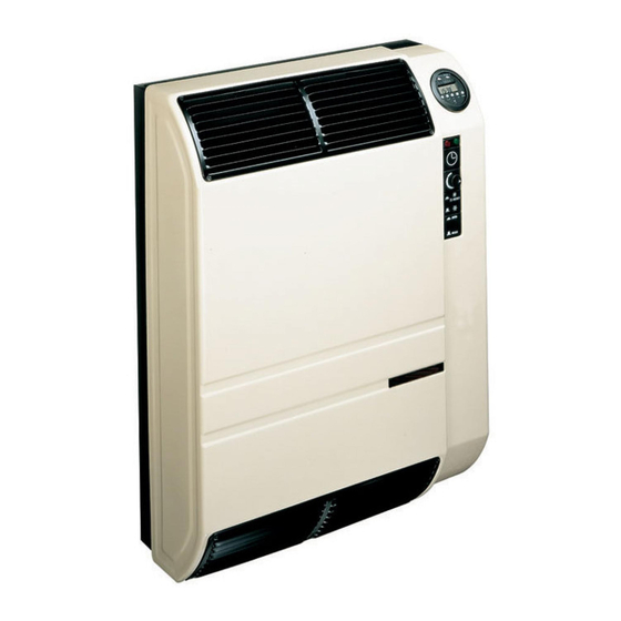
SUPERCROMO Series 1.1 PRODUCT DESCRIPTION AND MAIN OPERATING CHARACTERISTICS The Supercromo gas heater, is an independent heating product with an isolated combustion chamber and forced draught. It can operate either with natural gas and liquid propane gas (category II , type C , regulation EN 1266). -
Page 6: Technical Data
SUPERCROMO Series 1.2 TECHNICAL DATA DESCRIPTION U.M. 3001 3002 4001 4002 TYPE OF EQUIPMENT UNIT CATEGORY 2H3+ NOMINAL HEAT INPUT 2,58 2,58 3,25 3,62 kcal/h 2218 2218 2795 3116 NOMINAL HEAT OUTPUT 2,32 2,32 2,92 3,26 kcal/h 2000 2000 2511... - Page 7 SUPERCROMO Series TECHNICAL DATA DESCRIPTION U.M. 5001 5002 8001 8002 TYPE OF EQUIPMENT UNIT CATEGORY 2H3+ NOMINAL HEAT INPUT MAX 4,65 5,23 7,70 7,70 kcal/h 4000 4500 6590 6590 NOMINAL HEAT OUTPUT MAX 4,19 4,71 6,98 6,98 kcal/h 3600 4050...
-
Page 8: Installation
SUPERCROMO Series 2 INSTALLATION 10 cm 10 cm Figure 1 – EXTERNAL DIMENSIONS AND INSTALLATION LIMITS FOR MODELS 3001 AND 3002 10 cm 10 cm Figure 2 – EXTERNAL DIMENSIONS AND INSTALLATION LIMITS FOR MODELS 4001-5001 AND 4002-5002 Installation, Maintenance and User Manual - 10/2014... - Page 9 SUPERCROMO Series 10 cm 10 cm Figure 3 – EXTERNAL DIMENSIONS AND INSTALLATION LIMITS FOR MODELS 8001 AND 8002 Installation of this appliance must be in accordance with international and nationals regulations in force and carried out by qualified engineers following the instructions of the manufacturer.
- Page 10 SUPERCROMO Series Below is a table detailing the pressure loss values of bends and pipes with an internal diameter of 33 mm. 3001 5001 8001 DESCRIPTION U.M. 4001 4002 3002 5002 8002 AIR INTAKE PIPE INTERNAL DIAM 33 MM Pa/m...
-
Page 11: Installation Procedures
SUPERCROMO Series 3. In case a shelf is to be installed above the unit, a minimum distance of 100 mm from the unit is to be needed. No further covering panels can be placed around the unit. 4. Make sure there is an adequate gas supply through a proper gas pipe network. - Page 12 SUPERCROMO Series supporting frame staffa di sostegno guarnizione adesiva adesive gasket tubo aria air inlet pipe diameter 49 mm Figure 7 – POSITIONING OF SUPPORTING FRAME AND DRILLING PROCEDURE FOR 3001 AND 3002 MODELS supporting frame with bracket staffa di sostegno...
- Page 13 SUPERCROMO Series 5. Locate the supporting bracket and the pipe diameter 49 mm, making sure that the pipe edge perfectly enters the matching hole in the supporting frame (see Figure 7, Figure 8 and Figure 9). 6. Fix the supporting bracket with the screws and place the adhesive seal around the air inlet pipe hole (see Figure 7, Figure 8 and Figure 9).
- Page 14 SUPERCROMO Series pressure against the wall (see Figure 17). Install the heating body of the unit to the supporting bracket with the two lateral screws (see reference B in Figure 17). In case of special installations, also use the four screws located at the edges of the unit (see reference E - Figure 19).
- Page 15 SUPERCROMO Series Figure 17 – FIXING OF THE UNIT TO THE SUPPORTING BRACKET 8001 AND 8002 MODELS 13. For models 3001 and 3002 fix the units to the support A (see details on Figure 17) with a light pressure on the wall.
- Page 16 SUPERCROMO Series 21. When installation is complete proceed with the location of the aluminium terminal grid to the external wall. The terminal grid should perfectly match the pipe end. Draw the location of the three holes for the screw anchors (see Figure 23). The exhaust fumes grid must be installed vertically 22.
- Page 17 SUPERCROMO Series SUPPLY LOCATIONS 4001, 4002 AND 5001 MODELS Figure 21 – SUPPLY LOCATIONS 8001 MODEL Figure 20– Figure 22 - SUPPLY LOCATIONS FOR 3001 AND 3002 MODELS Figure 23 - TERMINAL GRID INSTALLATION Installation, Maintenance and User Manual - 10/2014...
-
Page 18: Gas Pressure Adjustment
SUPERCROMO Series 2.2 GAS PRESSURE ADJUSTMENT WARNING After accurate setting the valve pressure regulation screw must be safely sealed. The gas feeding circuit is provided with a gas valve equipped with double knock and pressure regulator to control the gas inlet flow. All models are supplied to operate with natural gas and are equipped with an LPG conversion kit (see paragraph of conversion to another type of gas). -
Page 19: Natural Gas Feeding
SUPERCROMO Series 2.2.1 NATURAL GAS FEEDING To regulate the unit, remove the casing (Figure 10 and Figure 11), check the fuel supply (natural gas) and proceed as follows: PRESSURE REGULATION TO THE BURNER (3001, 3002, 4001, 4002, 5001 AND 8001 MODELS) 1. -
Page 20: Replacement Of The Burner Injector
SUPERCROMO Series 5. Disconnect the pressure regulator tightening completely screw B (see Figure 26). In this way the pressure to the burner is directly depending on the distribution network pressure level. Make sure it is properly regulated at 30 mbar (for G30 gas) or at 37 mbar (for G31 gas). The network pressure level can be reduced by using a special first stage pressure reducers placed close to the liquid propane tank (for reduction down to 1,5 ate). -
Page 21: Conversion To Another Type Of Gas
SUPERCROMO Series 3001 8001 NATURAL GAS U.M. 4001 4002 5001 5002 3002 8002 DIAMETER NOZZLE 1,45/1,70 1,75/1,80 1,85 2,10 2,30 2,45/3,30 PRINTED REFERENCE Table 5 - GAUGED NOZZLES GAS NATUALE 3001 8001 L.P.G. U.M. 4001 4002 5001 5002 3002 8002... -
Page 22: Wiring Connections
SUPERCROMO Series 2.5 WIRING CONNECTIONS All units are standard supplied for single phase operations at 230 - 240 V 50 Hz depending on the model. The absorbed power varies from model to model (see Table 1 and Table 2). When carrying out wiring connections pay attention to the correct polarity (see Figure 29 or Figure 30). - Page 23 SUPERCROMO Series EV1 Solenoid gas valve for maximum RP7 Ignition electrode output RP8 Detection electrode EV2 Solenoid gas valve for minimum Combustion air blower output Shutdownred pilot light F.A. Suppression filter Working green pilot light Line Limit Thermostat Model 8002 is equipped with 2 fans...
-
Page 24: Use And Operation Of The Units
SUPERCROMO Series 3 USE AND OPERATION OF THE UNITS WARNING: FIRST UNIT START UP The first start up of the unit must be carried out by qualified service engineer. Before turning the unit on the qualified service engineer must check: •... -
Page 25: Turning Off Of The Unit
SUPERCROMO Series WARNING For all models 3002, 4002, 5002 and 8002 make sure that the ”A” commutator of the programmable timer (see Figure 32) is in position I in case the unit is required to operate under the control of the room thermostat or in position AUTO in where the unit is required to operate by means of the programmable timer. -
Page 26: Programmable Timer
SUPERCROMO Series 4 PROGRAMMABLE TIMER Figure 32 - PROGRAMMABLE TIMER On / Off switch Pos. I: The appliance is controlled by the room thermostat Pos. AUTO: The appliance is controlled by the timer and the room thermostat Pos. O: The appliance is turned off Setting / regulation switch Pos. -
Page 27: Setting And Adjustment
SUPERCROMO Series 4.3 SETTING AND ADJUSTMENT INITIAL CONDITIONS 1 2 3 4 5 6 7 0:00 A) Make sure that the B selector is in RUN position. After pressing the reset button R, the display starts flashing. 1 2 3 4 5 6 7... - Page 28 SUPERCROMO Series PROGRAMMING THE TIMER NOTE 16 different switch can be programmed on the timer: • 8 for ”ON” (1-3-5-7-9-11-13-15) which are shown by a light on the right end of the display • 8 for ”OFF” (2-4-6-8-10-12-14-16) no light When there is no light on the display means that the program is off.
- Page 29 SUPERCROMO Series DELETE A SETTING For deleting a single programme, proceed as follows: A) Move the right selector (see ref. B in Figure 32) in position. Press the button and select the programme it has to be changed. 1 2 3 4 5 6 7 B) Press button and button SKIP at the same time (see ref.
-
Page 30: Maintenance And Service
SUPERCROMO Series 5 MAINTENANCE AND SERVICE WARNING Maintenance and Service must be carried out only by qualified service personnel. 5.1 SAFETY DEVICES 1. Isolation of electrical supply: the unit stops working and the gas valve closes, when electricity reconnected the unit will automatically re-start working 2. -
Page 31: Improper Operating Procedures
SUPERCROMO Series 5.2 IMPROPER OPERATING PROCEDURES Before making any direct control on the unit make sure that: There is a full electricity supply. There is a full gas supply. The feeding pressure to the burner is within the tolerances given. -
Page 32: Servicing
SUPERCROMO Series Figure 36 – MODEL 8002 LOWER GRIDS POSITIONS. 5.5 SERVICING For all installation, start up and servicing operation contact qualified service engineer. Before calling for servicing, make sure that the manual as well as all the unit technical data is available namely:... - Page 33 SUPERCROMO Series With the aim of continuously improving the quality of our products, Robur reserves the right to vary the above instructions and drawings without any prior notice. ROBUR S.p.A. Via Parigi, 4/6 24040 Verdellino/Zingonia (Bergamo) - ITALY Tel. +39035- 888111 Fax +39035 - 884165 INTERNET: www.robur.it...
- Page 36 Muoverci dinamicamente, nella ricerca, sviluppo e diffusione di prodotti sicuri, ecologici, a basso consumo energetico, attraverso la consapevole responsabilità di tutti i collaboratori. La Mission Robur Robur Spa tecnologie avanzate per la climatizzazione Via Parigi 4/6 24040 Verdellino/Zingonia (Bg) Italy T +39 035 888111 F +39 035 884165 www.robur.it...
Need help?
Do you have a question about the Supercromo Series and is the answer not in the manual?
Questions and answers