Tennant T16 Operator's Manual
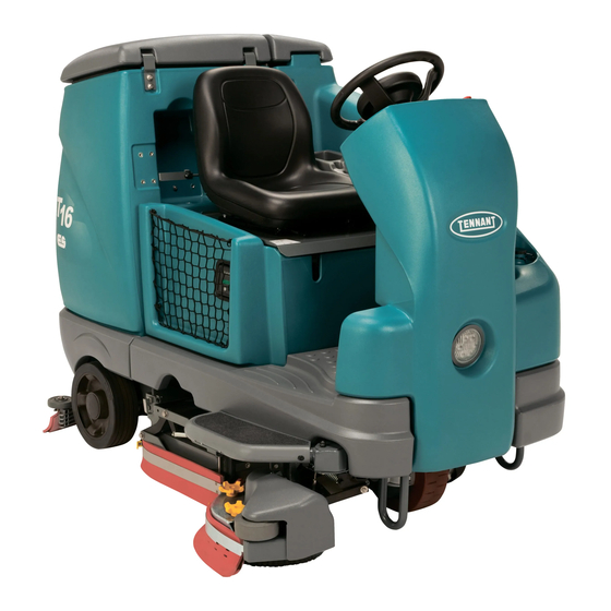
Rider scrubber
Hide thumbs
Also See for T16:
- Service information manual (200 pages) ,
- Operator's manual (82 pages) ,
- Instruction bulletin (10 pages)

Subscribe to Our Youtube Channel
Related Manuals for Tennant T16


Summary of Contents for Tennant T16
- Page 1 (Battery) Rider Scrubber English EN Operator Manual 9008308 For latest Parts manual or other Rev. 06 (6-2016) language Operator manuals, visit: *9008308* www.tennantco.com/manuals...
- Page 2 Installation Date − INTENDED USE The T16 is an industrial/commercial rider machine designed to wet scrub both rough and smooth hard surfaces (concrete, tile, stone, synthetic, etc). Typical applications include schools, hospitals / health care facilities, office buildings, and retail centers. Do not use this machine on soil, grass, artificial turf, or carpeted surfaces. This machine is intended for indoor use only.
-
Page 3: Table Of Contents
(Machines Without Optional Machine Troubleshooting ....Ec−H2o System) ....T16 9008308 (12−2015) - Page 4 ....Side Brush Solution Flow Rate (Option) Machine Dimensions ....T16 9008308 (10−2013)
-
Page 5: Important Safety Instructions − Save These Instructions
− With pads or accessories not supplied WARNING: Batteries emit hydrogen gas. or approved by Tennant. The use of Explosion or fire can result. Keep other pads may impair safety. sparks and open flame away. Keep −... -
Page 6: Safety Precautions
− Always follow safety and traffic rules. − Do not modify the machine from its − Report machine damage or faulty original design. − Use Tennant supplied or approved operation immediately. − Follow mixing, handling and disposal replacement parts. − Wear personal protective equipment instructions on chemical containers. - Page 7 Located on underside of Located on underside of solution tank cover. recovery tanks cover and on circuit breaker panel. Located on seat panel. FOR SAFETY LABEL − Read manual before operating machine. Located on circuit breaker panel. T16 9008308 (10−2014)
-
Page 8: Operation
D. Solution tank cover M. Side brush (option) E. Solution tank N. Operator seat F. Rear squeegee O. FaST PAK (option) G. Side squeegee ec−H20 System Module (option) H. Scrub head FaST solution system (option) I. Battery compartment T16 9008308 (12−2011) -
Page 9: Controls And Instruments
C. Side brush switch (option) D. Spray nozzle switch (option) E. Brake pedal F. Propel pedal G. Directional switch H. Operating lights / hazard lights switch I. Key switch J. Pre−Sweep switch (option) K. Power kill switch T16 9008308 (12−2011) -
Page 10: Touch Panel
M. Scrub mode (ec−H2O / FaST / ES / conventional) button N. Vacuum fan / squeegee button O. Solution increase button (+) P. Solution decrease button (−) Q. Solution on / off buttons R. Solution flow indicator lights T16 9008308 (3−2011) -
Page 11: Symbol Definitions
Pre−sweep / Vacuum fan Decrease Main brush pressure Side brush Solution On / Off Battery charge Emergency shutoff Horn Contrast control Hour meter Jack point Solution tank Solution flow (maximum / minimum) Brush pressure Forward / Reverse (maximum / minimum) T16 9008308 (3−2011) -
Page 12: Installing Batteries
Foam Spacer Foam Spacer Front of machine 5. Using the supplied battery post boots, connect the cables to the battery posts, RED TO POSITIVE (+) & BLACK TO NEGATIVE (−). 6. Reinstall the accessory box and tray. T16 9008308 (10−2014) -
Page 13: Operation Of Controls
(lowest bar on the indicator) unless the batteries have been fully charged. HOUR METER The Hour meter records the hours the machine was operated. Use this information to determine machine service intervals. T16 9008308 (10−2014) -
Page 14: Power Kill Switch
Operating and Hazard Lights On: Press the top of the Operating / hazard light switch. Operating Lights On: Press the Operating / hazard light switch to the middle position. All Lights Off: Press the bottom of the Operating / hazard light switch. T16 9008308 (12−2011) -
Page 15: Operator Seat
SEAT BELTS FOR SAFETY: Before starting machine, adjust seat and fasten seat belt. The weight adjustment knob controls the firmness of the operator seat. Use the gauge next to the weight adjustment knob to help determine seat firmness. T16 9008308 (3−2011) -
Page 16: Contrast Control Button
Press the propel the configuration and diagnostic modes. Only pedal to move the machine. properly trained service personnel and TENNANT representatives should access these modes. NOTE: An audible alarm will sound when the Directional switch is placed into reverse. -
Page 17: Vacuum Fan / Squeegee Button
Turn on the solution flow: Press the Solution on / off button to turn on the solution flow. The solution indicator lights will turn back on and the solution flow will default to the last setting used. T16 9008308 (3−2011) -
Page 18: How The Machine Works
FaST scrubbing system mixes the FaST−PAK concentrate with a small amount of water, creating a large volume of expanded wet T16 With Disk Brushes foam. The FaST system can be used with all scrubbing applications. When in the optional ec−H2O (electrically... -
Page 19: Brush And Pad Information
Polypropylene brush (Cylindrical and Disk)* − short bristles, or “tufts,” on the back to hold the General purpose polypropylene bristles lift lightly pad in place. This driver works with all Tennant compacted dirt without scuffing high-gloss coated pads except the black high productivity pad. -
Page 20: While Operating The Machine
Do not operate machine in areas where the ambient temperature is above 43_ C (110_ F). Do not operate scrubbing functions in areas where the ambient temperature is below freezing 0_ C (32_ F). T16 9008308 (10−2014) -
Page 21: Pre−Operation Checklist
- Confirm the vacuum fan inlet filter is clean. - Check the right side squeegee for wear and damage. - Machines equipped with ES option: Ensure ES filter at bottom of recovery tank is clean. T16 9008308 (10−2014) -
Page 22: Starting The Machine
Drain, rinse, and refill the solution tank with clear cool water before operating the FaST or ec−H2O system. Conventional cleaning detergents may cause a FaST or ec−H2O system failure. 3. Close the solution tank cover. T16 9008308 (10−2014) -
Page 23: Conventional Scrubbing Mode
Machine damage due to improper detergent usage will void the manufacturer’s warranty. NOTE: Pour a recommended foam control solution into the recovery tank if excessive foam appears. For specific detergent recommendations, contact a Tennant representative. 3. Close the solution tank cover. T16 9008308 (10−2014) -
Page 24: Es (Extended Scrub) Mode
50 mm (2 in) below the indicator tab. 3. Fill the recovery tank with water (not to exceed 60°C / 140°F). Fill the recovery tank to just above the top of the ES filter. T16 9008308 (10−2014) -
Page 25: Setting Scrub Modes
(one light) allows solution flow WITHOUT adding detergent. Detergent does not have to be continuously added with the solution flow to attain effective scrubbing results. Under normal soilage conditions, the solution flow level should be alternated between the middle and lowest setting. T16 9008308 (3−2011) -
Page 26: Scrubbing
4. If necessary, adjust the brush pressure and delay. solution flow. 5. Place the directional switch in the direction the machine is to be moved (forward or reverse). 6. Press the propel pedal to begin scrubbing. T16 9008308 (3−2011) -
Page 27: Double Scrubbing
Scrub the heavily soiled area. Let the cleaning solution soak on the floor for 5−15 minutes. FOR SAFETY: When using machine, go slowly on inclines and slippery surfaces. T16 9008308 (3−2011) -
Page 28: Water Pickup Mode (No Scrubbing)
Do not pick up. Press the Vacuum fan/squeegee button. The light above the button will come on, the squeegee will lower, and the vacuum fan will start operating. Pick up the water or non−flammable liquid spill. T16 9008308 (3−2011) -
Page 29: Draining And Cleaning The Recovery Tank
3. Hold the drain hose near a floor drain, twist the drain nozzle open, and place the hose near the floor drain. NOTE: Be sure the drain hose nozzle is pointed in a safe direction before opening the nozzle. T16 9008308 (6−2016) - Page 30 NOTE: The scrub head must be lowered hose back onto the recovery tank. approximately 25 mm (1 in) to remove debris trough. NOTE: The debris trough can be removed from the right side of the machine only. T16 9008308 (6−2016)
-
Page 31: Draining And Cleaning The Solution Tank (Es Machines Only)
NOTE: Be sure the drain hose nozzle is pointed in a safe direction before opening the nozzle. NOTE: DO NOT use steam to clean the tanks. Excessive heat can damage the tanks and components. T16 9008308 (10−2014) -
Page 32: Turn Off The Machine
2. Press the 1−Step button to stop scrubbing. 3. Press the brake pedal to stop the machine. 4. Turn the key switch to the off position. 7. Twist the drain cuff closed and hook the drain hose back onto the solution tank. T16 9008308 (10−2014) -
Page 33: Fault Indicator(S)
F3: Vac # Flt # vacuum fan motor(s) not Shut off and restart machine. operating If fault code still appears, stop using machine and contact Tennant service representative. F4: Batt Very Low Low battery charge Recharge battery F5: Propel Error Propel controller error Turn off and restart machine. -
Page 34: Warning Codes
Right / rear brush not operating If warning code still appears, stop using W10: Open L/F Brush Left / front brush not operating machine and contact Tennant service W11: Open SD Brush Side brush not operating representative. W12: Solution Off... -
Page 35: Options
5. Press the bottom of the side brush switch to stop and raise the side brush. 4. Press the bottom of Pre−Sweep switch to shut off the Pre−sweep system and dust control system. T16 9008308 (12−2011) -
Page 36: Empty The Pre−Sweep Debris Hopper
1. Lift the Pre−Sweep assembly cover and lock the cover open. 5. Unlock and lower the Pre−Sweep cover. 2. Remove the debris hopper from the Pre−Sweep assembly and empty the hopper. 3. Reinstall the debris hopper into the Pre−Sweep assembly. T16 9008308 (10−2014) -
Page 37: Vacuum Wand (Option)
3. Insert the vacuum wand cap into the vacuum port in the vacuum wand. 7. When finished vacuuming, press the Vacuum fan/squeegee button to turn off the vacuum fan. The squeegee will raise. 8. Turn off the machine. T16 9008308 (10−2014) -
Page 38: Adjusting Backup Alarm Volume (Option)
11. Insert the vacuum hose into the vacuum hose recess in the recovery tank. 12. Snap the vacuum wand lanyard onto the solution tank to secure the vacuum wand / squeegee vacuum hose to the machine. T16 9008308 (6−2016) -
Page 39: Rollout Battery (Option)
6. Step on the left side of floor lock to set the battery cart floor lock. 4. Push the battery cart to the operator side of the machine and align the battery cart with the battery compartment. T16 9008308 (10−2014) -
Page 40: Rear Squeegee Guard (Option)
To engage the rear squeegee protector, pull the pin, lower the protector bar, and reinsert the pin. 9. Pull up on the handle to lower the cart battery stop bar. This will keep the batteries from rolling off the cart. T16 9008308 (3−2011) -
Page 41: Spray Nozzle (Option)
3. Pull the spray nozzle out from the back of the machine and clean as needed. FOR SAFETY: Wear eye and ear protection when using pressurized air or water. T16 9008308 (10−2014) - Page 42 OPERATION T16 9008308 (3−2011)
-
Page 43: Machine Troubleshooting
Pre−Sweep option only) mechanism mechanism. Hopper full Empty hopper Vacuum debris bag full Replace vacuum debris bag Recirculation skirt damaged Replace recirculation skirt Wrong sweeping brush Contact TENNANT representative for recommendations Main brush drive failure Contact TENNANT service personnel T16 9008308 (3−2011) - Page 44 Mineral deposit build−up in Flush module (See ec−H2O Warning and fault indicator light module MODULE FLUSH blinking red PROCEDURE) ec−H2O Model: Clogged module Contact Service Center Warning and fault indicator light Defective solution pump Replace solution pump solid red T16 9008308 (3−2011)
-
Page 45: Product View
MAINTENANCE MAINTENANCE 356071 T16 9008308 (10−2014) -
Page 46: Maintenance Chart
Battery terminals and Check and clean cables Hours − Cylindrical brush drive Check for damage and belts wear − Pre−Sweep brush drive Check for damage and belt wear Steering chain Lubricate, check tension, and check for damage and wear. T16 9008308 (10−2014) - Page 47 LUBRICANT/FLUID ..Distilled water..Special lubricant, Lubriplate EMB grease (Tennant part number 01433−1) ..SAE 90 weight gear lubricant NOTE: More frequent maintenance intervals may be required in extremely dusty conditions.
-
Page 48: Yellow Touch Points
STEERING CHAIN The steering chain is located on the steering column directly under the control panel. Check for damage or wear and lubricate the steering chain after every 200 hours. T16 9008308 (6−2016) -
Page 49: Batteries
Proceed to the BATTERY WATERING SYSTEM (OPTION). 08247 FOR SAFETY: When servicing machine, keep all metal objects off batteries. Avoid contact with battery acid. T16 9008308 (6−2016) -
Page 50: Charging The Batteries (Off−Board Charger)
6. The Tennant charger will start automatically. When the batteries are fully charged, the Tennant charger will automatically turn off. 7. After the charger has turned off, unplug the charger connector from the remote battery charge connector. -
Page 51: Circuit Breakers
Carbon Brush Inspection Hours Main Brush Motors 1000* Pre−Sweep Main Brush Motors 1000* Side Brush Motor (Option) 1000* Vacuum Motor *Inspect carbon brushes every 100 hours after the initial 1000 hour change. T16 9008308 (10−2014) -
Page 52: Scrub Brushes
NOTE: Always replace brushes and pads in sets. Otherwise one brush or pad will be more aggressive than the other. 5. Squeeze the spring handles and let the brushes drop to the floor. Remove the brush from under the scrub head. T16 9008308 (6−2016) -
Page 53: Replacing Disk Scrub Pads
9. Close and secure the left side squeegee pad driver. assembly. 5. Reinstall the pad driver onto the machine. 10.Repeat procedure for the other brush. T16 9008308 (6−2016) -
Page 54: Cylindrical Brushes
8. Repeat for the other brush on the other side of the scrub head. NOTE: Do not switch the left or right idler plates or the brushes will need to be readjusted by trained personnel. T16 9008308 (10−2014) -
Page 55: Side Brush (Option)
7. Place the new side brush underneath the side brush assembly and lift the side brush up onto the side brush hub until the brush locks onto the hub. 8. Reinstall the side brush squeegee assembly onto the side brush assembly. T16 9008308 (6−2016) -
Page 56: Pre−Sweep Brushes (Option)
5. Remove the side brush from under the Pre−Sweep assembly. 6. Install the new side brush onto the Pre−Sweep side brush assembly. 3. Turn off the machine. FOR SAFETY: Before leaving or servicing machine, stop on level surface, turn off machine, and remove key. T16 9008308 (10−2014) -
Page 57: Replacing The Pre−Sweep Cylindrical Brush (Option)
4. Remove the left brush arm. 7. Remove the cylindrical brush and replace with a new brush. 8. Guide the slotted end of the new brush onto the drive hub. 9. Reinstall the side skirt, side skirt plate, and left brush arm. T16 9008308 (3−2011) -
Page 58: Fast System
NOTE: The FaST−PAK Floor Cleaning Concentrate is specially designed for use with the FaST system scrubbing application. NEVER use a substitute. Other cleaning solutions may cause FaST system failure. 4. Slide the FaST−PAK carton into the FaST−PAK bracket. T16 9008308 (10−2014) -
Page 59: Ec−H2O Module Flush Procedure
3. Remove the drain hose from the ec−H2O compartment. 6. Place the drain hose into a empty container. 7. Pour 2 gallons (7.6 liters) of white or rice vinegar into the solution tank. T16 9008308 (10−2014) - Page 60 13. Reconnect the outlet hose to the the scrub head to the ec−H2O manifold hose. 14. Place the drain hose back into the ec−H2O compartment. 15. Reinstall the ec−H2O compartment cover. 16. Close the operator seat cover. T16 9008308 (7−2012)
-
Page 61: Squeegee Blades
1. Lower the scrub head. FOR SAFETY: Before leaving or servicing machine, stop on level surface, turn off machine, and remove key. 2. Disconnect the vacuum hose from the rear squeegee assembly. 4. Pull the rear squeegee assembly from the machine. T16 9008308 (10−2014) - Page 62 10. Install the rotated or new squeegee blade into the outer frame. Be sure the squeegee is 7. Slide both retainers out away from the completely slid down onto each tab on the squeegee assembly. outer frame. T16 9008308 (10−2014)
- Page 63 13. Place the rotated or new squeegee blade onto the inner frame. Be sure the squeegee is securely attached on each tab on the inner frame. T16 9008308 (10−2014)
-
Page 64: Leveling The Rear Squeegee
7. Drive the machine forward with the squeegee 4. To adjust the squeegee leveling, loosen the tilt down to recheck the squeegee blade lock knob. deflection if adjustments were made. 8. Readjust the squeegee blade deflection if necessary. T16 9008308 (10−2014) -
Page 65: Adjusting The Rear Squeegee Blade Deflection
12 mm (0.50 in) for scrubbing smooth floors and 15 mm (0.62 in) for rough floors. 5. Retighten the lock knob. 6. Drive the machine forward again to recheck the squeegee blade deflection. 7. Readjust the squeegee blade deflection if necessary. T16 9008308 (10−2014) -
Page 66: Replacing Or Rotating The Side Squeegee Blades
8. Fasten the retaining band latch onto the side squeegee assembly. 9. Repeat for the side squeegee on the other side of the scrub head. 4. Remove the retaining band from the side squeegee assembly. T16 9008308 (10−2014) -
Page 67: Replacing Or Rotating The Side Brush Squeegee Blades (Option)
FOR SAFETY: Before leaving or servicing machine, stop on level surface, turn off machine, and remove key. 4. Loosen the retaining band latch. T16 9008308 (10−2014) - Page 68 Install / reinstall squeegees so the deflection is NOTE: Observe which squeegee slots were approximately 12 mm (0.50 in) for smooth floors installed on the squeegee frame before removing and 15 mm (0.62 in) for rough floors. the squeegee. T16 9008308 (10−2014)
- Page 69 MAINTENANCE 6. Install the rotated / new squeegee blades and retainer onto the side brush assembly. 7. Fasten the side brush retaining band latch. 8. Reinstall the side brush squeegee assembly onto the side brush assembly. T16 9008308 (10−2014)
-
Page 70: Skirts And Seals
Check the skirts for damage and wear after every 50 hours of operation. PRE−SWEEP RECIRCULATION SKIRT (OPTION) The Pre−Sweep recirculation skirt is located behind the main sweeping brush. Check the skirt for damage and wear after every 50 hours of operation. T16 9008308 (10−2014) -
Page 71: Belts
The machine has three solid rubber tires: one in front, and two in the rear of the machine. Check tires for damage and wear after every 500 hours of operation. T16 9008308 (10−2014) -
Page 72: Pushing, Towing, And Transporting The Machine
FOR SAFETY: When loading/unloading machine. machine onto/off truck or trailer, drain tanks before loading machine. 2. Position the machine at the loading edge of the truck or trailer. T16 9008308 (10−2014) - Page 73 The front tie−down locations are the stabilizer machine off the truck or trailer unless the legs. loading surface is horizontal AND 380 mm (15 in) or less from the ground. The rear tie-down locations are the holes in the frame. T16 9008308 (10−2014)
-
Page 74: Machine Jacking
FOR SAFETY: When servicing machine, block machine tires before jacking machine up. Use a hoist or jack that will support the weight of the machine. Jack machine up at designated locations only. Support machine with jack stands. T16 9008308 (6−2016) -
Page 75: Freeze Protection (Machines Without Optional Ec−H2O System)
12. Machines equipped with the optional spray nozzle only: Operate the wand for a few seconds to protect the pump. 13. Turn off the machine. 14. The remaining RV antifreeze does not need to be drained from the solution tank. T16 9008308 (10−2014) -
Page 76: Preparing The Machine For Operation (Machines Without Optional Ec−H2O System)
RV antifreeze from the pump. 10. Turn off the machine. 11. The remaining water does not need to be drained from the solution tank. 4. Turn on the machine 5. Press the 1−STEP button. T16 9008308 (10−2014) -
Page 77: Freeze Protection (Machines With Optional Ec−H2O System)
5. Lift the operator seat open and engage the seat support bar. 9. Connect the drain hose to the ec−H2O 6. Remove the ec−H2O compartment cover. manifold hose disconnected from the outlet hose in the previous step. T16 9008308 (10−2014) - Page 78 14. Reconnect the outlet hose to the scrub head to the ec−H2O manifold hose. 15. Place the drain hose back into the ec−H2O compartment. 16. Reinstall the ec−H2O compartment cover. 17. Close the operator seat cover. T16 9008308 (10−2014)
-
Page 79: Priming The Ec−H2O System
3. Remove the drain hose from the ec−H2O 10. Reconnect the outlet hose to the scrub head compartment. to ec−H2O manifold hose. 11. Place the drain hose back into the ec−H2O compartment. 12. Reinstall the ec−H2O compartment cover. 13. Close the operator seat cover. T16 9008308 (3−2011) -
Page 80: Specifications
62 dB(A) 62 dB(A) Sound uncertainty K 4 dB(A) 3 dB(A) Sound power level L + Uncertainty K 89 dB(A) 86 dB(A) Vibration − Hand−arm <2.5 m/s <2.5 m/s Vibration − Whole body <0.5 m/s <0.5 m/s T16 9008308 (6−2016) -
Page 81: General Machine Performance
0.49 LPM (0.13 GPM) equipped with optional side brush) Detergent flow rate (at main brushes) 1.14 CC/Minute (0.038 Ounces/Minute) Detergent flow rate (at side brush − if machine is 0.47 CC/Minute (0.016 Ounces/Minute) equipped with optional side brush) T16 9008308 (10−2014) -
Page 82: Ec−H2O System (Option)
2.84 LPM (0.75 GPM) − (To main scrub head) Solution flow rate (machines with optional side brush) 0.95 LPM (0.25 GPM) − (To side brush) SIDE BRUSH SOLUTION FLOW RATE (OPTION) Item Measure Solution pump 36 Volt DC, 0.33A, 58.7 LPH (15.5 GPH) open flow T16 9008308 (10−2014) -
Page 83: Machine Dimensions
SPECIFICATIONS MACHINE DIMENSIONS Rear Squeegee 1090mm (43 in) 2080 mm (82 in) 1475 mm (58 in) Frame 1880 mm (roller to roller) (74 in) 1040 mm (41 in) Width (with side brush) 1170 mm (46 in) T16 9008308 (10−2014)
Need help?
Do you have a question about the T16 and is the answer not in the manual?
Questions and answers