
Related Manuals for Osaki OS4000


Summary of Contents for Osaki OS4000
- Page 1 OS4000 Maintenance Service Manual MODEL: OS4000 Voltage specification:110-120V By Customer Service Department PDF 文件使用 "pdfFactory Pro" 试用版本创建 www.fineprint.com.cn...
- Page 2 Model OS4000 Table of Contents I……Specifications ……………………………………………………….3 II.…..Appearance of the chair …………………………………………….4 III…. Name and functions of components (remote controller) …………...5 IV…..Malfunction catalog………………………………………………6~8 V……Troubleshooting flow chart……………………………………..9~13 VI……Maintenance of the back rest …………………………………14~19 VII…..Maintenance of the seat part ………………………………….20~25 VIII….Maintenance of the footrest …………………………………..26~29 PDF 文件使用...
- Page 3 I. Specifications PDF 文件使用 "pdfFactory Pro" 试用版本创建 www.fineprint.com.cn...
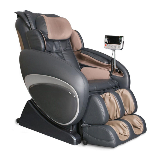
- Page 4 II. Appearance of the chair PDF 文件使用 "pdfFactory Pro" 试用版本创建 www.fineprint.com.cn...
- Page 5 III.Name and functions of components (remote controller) Remote controller Auto-program buttons Main control buttons The adjustment button Length auto adjustment for back body buttons for legrest Angle adjustment button Sensor receiver Back speed/Air intensity Manual back massage programs PDF 文件使用 "pdfFactory Pro" 试用版本创建 ÿ www.fineprint.com.cn...
- Page 6 IV. Malfunction catalog Common Troubles and Maintenance Methods are listed as following: Serial Phenomenon Description Maintenance Methods Refer to The LCD isn’t illuminating: ① Replace Fuse(s). ① Page 25/20 ① Fuse(s) burn out ( the one ② Replace the power supply ②...
- Page 7 ①Terminal or Wire Poorly ①Plug the terminal securely ①Page Contacts. or replace the wires. 23-24/18 ②Down-stroke Photo- ②Replace Down-Stroke ②&③ Electricity Subassembly Fails. Subassembly. Page 19/8 No Rolling. ③Up-stroke Photo-electricity ③Replace Up-Stroke Sub- ④Page 17/6.2 ⑤Page Subassembly Fails. assembly. ④Rolling Motor Fails. ④Replace Rolling Motor.
- Page 8 ① The terminals of foot rest ①Plug the terminal securely. ①&②Page ②Replace foot rest actuator. Foot rest cannot actuator and wires are 22-23/16 ③Replace main PCB. ② Page 23-24 be raised or poorly connected. ②The foot rest actuator fails. lowered. ③Main PCB fails.
- Page 9 V. Troubleshooting flow chart Notes for repairing chair or replacing parts: ①Make sure the power is OFF before tearing down the wires, moving terminals or replacing parts. ②Semiconductors (such as IC and others) are very easy to be damaged by static, so when you touch the PCB, please make sure your body is grounding (by wearing a girding static ring), or your hands are touching with earthing grip (household electrical appliances putting to earth, such as fridges, washers and so on) to release all static of the body.
- Page 10 2. No width switchover. Are the terminals of Width Inspection Board and main PCB connected securely? Connect securely. Width Inspection Board fails or not? Replace it. (Page 18/7.1) Replace main PCB. (Page 23-24/18) 3. No function(fixed-spot or partial) Connect securely. Are the terminals of main PCB connected securely? Replace Main PCB.
- Page 11 5. No kneading Are the terminals of kneading motor wire and main Connect securely. PCB connected securely? Kneading motor fails or not? Replace the motor. (Page 16/6.1) Width Inspection Board fails or not? Replace it. (Page 18/7.1) Replace main PCB. (Page 23-24/18) 6.
- Page 12 8. Actuator doesn’t work. terminals Are the terminals of foot rest Connect Connect reclining actuator and main actuator main securely. securely. PCB connected securely? connected securely? The reclining actuator Replace it. The foot rest actuator Replace it. fails or not? fails or not? (Page 22/15) (Page 22-23/16)
- Page 13 Replace the motor Motor of the calves-rest fails (Page 26-27/23) Replace main PCB (Page 23-24/18) Common trouble about electric control and processing methods of OS4000 are mentioned above. It is for indication only. PDF 文件使用 "pdfFactory Pro" 试用版本创建 ÿ www.fineprint.com.cn...
- Page 14 VI. Maintenance of the back rest 1. Disassembly and replacement of back pad ① Find the zipper on the top of the back rest. Unzip it, then the back pad can be removed. ② There are two air hoses at the bottom of the back pad, pull out the connectors if a replacement needed. ③...
- Page 15 Lift the backrest at 90 degrees. A. Connecting rod (on the backrest) B. U stay fork of reclining actuator (on the seat) C. Flat head rivet D. Split pin Disconnect the air hose of the backrest 3. Replacement of cloth of the front cover ①...
- Page 16 4. Disassembly and replacement of the rear cover If you find any cracks on the rear cover, you can proceed as follow: ① Unfasten the zippers of the outer cloth of the rear cover. ② Find 4 pieces of screws fixing the rear cover. ③...
- Page 17 nipper pliers, then disconnect the wires. ④ Find 4 pieces of screws fixing the kneading motor to the sheet-metal, remove the screws with a plus screwdriver. ⑤ Replace a new one if it does work. ⑥ Proceed in the reverse order of disassembly when replacing a new one. Note:You should adjust the position of the small belt wheel, so the small and big belt wheels are in the same plane to prolong the life-span of the belt.
- Page 18 Screws securing the rolling motor (3 pcs) Screws (5pcs) securing the Rolling motor 6.3 Tapping motor(DC -24V) : ① Disassemble the rear cover, then find the tapping motor. ② Cut the cable ties securing the wire on the sheet-metal of EMC. ③...
- Page 19 7.2 Disassembly and replacement of the massage mechanism Note: If the swinging arms are broken or it is too noisy, you can try to do something to the massage mechanism. You should disassemble the rear cover and the cloth of the back rest. ①...
- Page 20 VII. Maintenance of the seat part 9. Replacement of the remote controller holder ① Pull out the remote controller from the holder. ② Remove the screw bolt tightening the holder. ③ Take away the holder from the support. ④ Install a new holder on the support. ⑤...
- Page 21 13. Replacement of the side board ① Disassemble the backrest from the chair ② Use a cable tie to unfasten the seat pad from the chair by the zippers. ③ Remove the screws (4pcs) securing the side board. ④ Disconnect the air hose of the side cover. ⑤...
- Page 22 14. Replacement of the seat pad ① Disassemble the backrest from the chair ② Use a cable tie to unfasten the seat pad from the chair by the zippers. ③ Pull out the air hose Y- connector of the seat pad. ④...
- Page 23 drop suddenly while pulling out plastic bush rings. ④ Pull out plastic bush rings, then the reclining actuator can be disassembled. ⑤ Proceed in the reverse order of disassembly when assembly. The connectors of the footrest actuator U stay forks 17 Disassembly of the zero gravity actuator ①...
- Page 24 ④ Pull out all the terminals on the main PCB, disconnect the PCB supports, then the main PCB can be removed. ⑤ Proceed in the reverse order of disassembly when assembly. Remove the screws(9pcs) on the box to take down the up cover of the main PCB box Main PCB Air valves...
- Page 25 20. Replacement of power supply fuse ② Find the fuse at the bottom of the seat part. Turn the fuse holder in the counterclockwise direction with a finger nail or a minus screwdriver. ③ Take out the fuse from the fuse holder and replace with a new one. ④...
- Page 26 IX. Maintenance of the foot rest 22. Replacement of the whole foot rest ① Turn on the power and raise the foot rest to the highest position. Then turn off the power. ② Remove the screws securing the front panel, take it away. ③...
- Page 27 wheel of belt on the shaft. ⑥ Proceed in the reverse order of disassembly when assembly. Note: You should adjust the position of the wheel of belt, so the two wheels are in the same plane. 24. Replacement of the front and back sensors of foot rest ①...
- Page 28 ④Remove the nuts fixing on the PCB. ⑤ Take a new PCB, then proceed in the reverse order of disassembly when assembly. 27. Replacement of upper outer coating of foot rest ① First you should disassemble the whole foot rest, and the cover of foot rest should be removed. ②...
- Page 29 ⑥ Remove the screws fixing the lower part of the foot rest, then the outer coating can be removed. ⑦ Proceed in the reverse order of disassembly when assembly. Castor taken down Screws fixing the lower part PDF 文件使用 "pdfFactory Pro" 试用版本创建 www.fineprint.com.cn...
Need help?
Do you have a question about the OS4000 and is the answer not in the manual?
Questions and answers