Table of Contents
Advertisement
Serial Number
Please quote this serial number when contacting CVO Fire.
•
It is recommended, even if you have installed these appliances before, that you take the
time to read through these instructions and follow them step by step.
•
The appliance is CE approved for use with Natural Gas – I2H, I2E, 2E+, I2L and LPG I3P, I3+,
I3B/P. Check the data plate for actual appliance setting.
•
This manual must be handed to the owner of the property once the appliance is
commissioned and retained onsite for operation and servicing reference.
•
The appliance has a manufacturer's warranty valid for 1 year from date of delivery. In order
to validate the warranty the appliance must be installed by a GAS SAFE Engineer.
•
The warranty card supplied with this booklet should be completed by the GAS SAFE Engineer
and posted to : Customer Service Dept, CVO Fire. 4 Beaumont Square, Aycliffe Industrial
Park, Newton Aycliffe. County Durham. DL5 6XN.
•
Whenever contacting CVO Fire regarding the appliance please have the serial number and the
installers GAS SAFE registration number available.
Fire Wave
INSTALLATION MANUAL
Important
Page 1 of 42
CE PIN NUMBER: 0063BT5051
Revision-7 [2011]
Advertisement
Table of Contents

Related Manuals for CVO Fire Fire Wave


Summary of Contents for CVO Fire Fire Wave
- Page 1 GAS SAFE Engineer. • The warranty card supplied with this booklet should be completed by the GAS SAFE Engineer and posted to : Customer Service Dept, CVO Fire. 4 Beaumont Square, Aycliffe Industrial Park, Newton Aycliffe. County Durham. DL5 6XN. •...
-
Page 2: Table Of Contents
Contents Appliance Technical Data Appliance General Information Warning for Fire Guards and Hearths Appliance Unpacking Instructions Remote Control System Appliance Installation Instructions Appliance Commissioning Instructions Appliance Start Up / Shut Down Instructions Appliance Fault Diagnosis Instructions Battery Remote System – Fault Diagnosis Battery Remote System - Schematic Appliance Cleaning Instructions Appliance Servicing Instructions... -
Page 3: Appliance Technical Data
inline with the instructions in this manual the owner will enjoy many years of enjoyment from the fireplace. Please take time to read the instructions fully. The installer is to advise the user not to stand too close to the appliance for prolonged periods of time and that loose clothing is particularly at risk of burning due to the presence of an unguarded flame. -
Page 4: Appliance General Information
2. Appliance General Information The appliance is intended for decorative purposes only. The chimney should be swept before the appliance is installed, and should be swept and inspected regularly to ensure that all products of combustion are entering the flue and there is no excessive build up of soot. -
Page 5: Remote Control System
5. Remote Control System Take some time to learn about the remote system fitted to this fire. Review the circuit diagram to familiarise yourself with the system components. This gas fire is operated by a remote control system which is powered by “AA” batteries. The fire is supplied with a remote hand set which will switch the fire on/off and regulate the flame up/down. -
Page 6: Appliance Installation Instructions
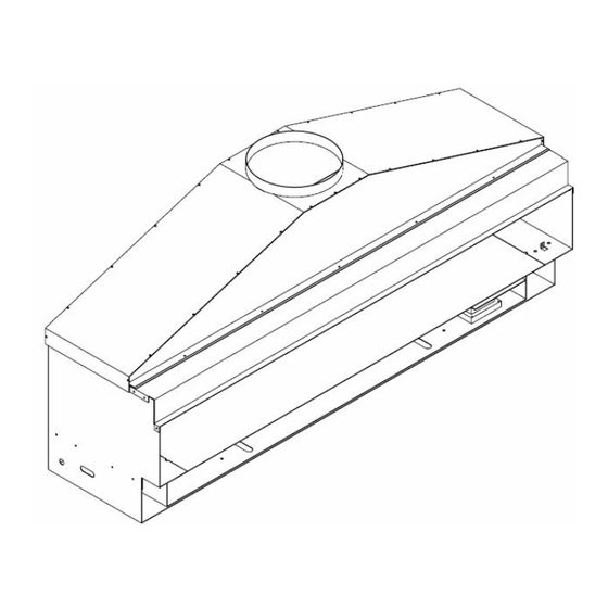
6. Appliance Installation Instructions (To be carried out by a Registered GAS SAFE Engineer only – failure to comply with this requirement will invalidate the Warranty) 6.1. General GATHER: This appliance is fitted with a gather unit which must be remaining attached to the appliance. -
Page 7: Side View
6.2 Burner Ventilation Requirements This fire is designed to be used as a “trimless” fire. For the fire to work correctly additional burner ventilation must be planned to provide fresh air into the burner box. This work should be planned before starting to install the fire. -
Page 8: Appliance Installation
There should be no reason to dismantle the appliance. The only connection required is an 8mm gas supply. The Fire Wave does not have its own support lintel. Therefore in some cases it may be necessary to install a lintel above the opening. Check with building regulations if in doubt. - Page 9 6.4 Gas Supply GAS FLOW RATES: NATURAL GAS 1.6m3/Hour LPG/PROPANE 0.6m3/Hour This is a high power [14KW] appliance and needs a very strong and constant gas supply. Before installing this appliance the gas pipe work needs to be reviewed to ensure the gas pressure at the appliance, when on full, remains at 20mBar at all times.
- Page 10 6.4 Final Checks before lighting the fire. NOTE – REMOTE SYSTEM The appliance is operated by 6 x “AA” batteries. It is advised that Lithium batteries are used to increase life. The fire is supplied with a Handset and a Magic Eye. There is the option to add a Manual Wall Switch.
-
Page 11: Appliance Commissioning Instructions
7. Appliance Commissioning Instructions The burner inlet flow rates are factory set and sealed. Under no circumstances should these settings be changed. The aeration is fixed. Do not change the burner aeration. Step 1: The appliance is supplied with a pressure test elbow and gas tap. Connect an 8mm gas supply to the tap and test for leaks. - Page 12 GAS SAFE registration number of the Engineer. If the appliance is not installed in strict accordance with these instructions CVO Fire cannot be held responsible for any damage caused and reserve the right to charge for any corrective work.
-
Page 13: Appliance Start Up / Shut Down Instructions
8. Appliance Start Up / Shut Down Instructions The appliance requires 6 x AA Lithium batteries to operate. The handset has a 9v battery. If the main burner or pilot light is extinguished during lighting, do not attempt to re- light the pilot within three minutes. - Page 14 • TO TURN APPLIANCE “ON” Press Button #1 & #2 at the same time and point directly at the magic eye. The buttons must be held for 3-5 seconds. This is a child safe system to stop accidental lighting. The ignition sequence will start. The gas to the pilot is opened and the magnet unit pressed by the motor, the spark is generated.
- Page 15 8.2 Using the Manual Control Panel. [if fitted] When fitting please ensure the cable does not become detached from the membrane. The membrane has a self adhesive pad which can be stuck to the wall. • Button #1 - By pressing this switch, this starts the ignition sequence (press &...
- Page 16 8.3 How to Shutdown the appliance if the appliance is lit and both the Handset and Wall Switch are Faulty. The appliance has a safety shut down switch which is built into the remote system. This is in the form of a button fitted inside the appliance. In the unlikely event that the handset is lost, damaged or broken and the manual wall switch is broken while the fire is lit the fire can be shutdown by pressing this button.
-
Page 17: Appliance Fault Diagnosis Instructions
9. Appliance Fault Diagnosis Instructions All CVO Fire appliances are bubble tested to 150mBar to ensure there are o gas leaks, they are then given a full function test for over 1 hour to ensure all functions and safety devices are inline with the CE approval. It is highly unlikely, that if the appliance has been installed correctly as set out in this manual that the appliance will not function. - Page 18 Remote Specific Symptom Check List Tick Check that the light on the remote handset are flashing when the buttons are pressed. Check you are using the correct lighting procedure as detailed in earlier section. Appliance does not respond to Check operation with the manual wall switch. commands from the remote control handset.
-
Page 19: Battery Remote System - Fault Diagnosis
9.b. Battery Remote System – Fault Diagnosis This fire is operated via a battery remote system with AA batteries. The remote system has a built in alarm system which indicates and faults which may arise. This is shown by a sequence of a pre-defined number of “beeps” corresponds to a certain failure. -
Page 20: Battery Remote System - Schematic
9.c. Battery Remote System – Schematic Schematic of Battery Remote System. All parts are required to ensure system operates safely and efficiently. To order replacement parts please call 01325-327221 and ask for customer service department. Page 20 of 42... -
Page 21: Appliance Cleaning Instructions
APPLIANCE - contact your installer to remove the spillage and ensure the remote system functions correctly. 11. Appliance Servicing Instructions CVO Fire recommends that the appliance is serviced every 12 months by a registered Engineer. Step 1: Turn off the appliance and allow it to cool. -
Page 22: Appliance Spare Parts
NG – 9103 – CVO Code - AC001 b. LPG - 9272 – CVO Code - AC058 To order spare parts please contact: CVO Fire Customer Service on 01325 327221. A full spare parts list can be emailed to you with images and codes. - Page 23 12.2 Spare Part Installation Procedure Step 1: Turn off the appliance and allow it to cool. Step 2: Turn off the gas supply stop tap. Step 3: Remove the front shelf and left hand support bracket. Step 4: Making a note of their positions, remove the Stop Button, Charge Socket and IR Receiver from the right hand shelf and thread through the aperture in the burner tray.
- Page 24 REMOVAL OF BURNER UNIT The main burner unit can be removed if required for repair or servicing by removing by following the below steps carefully. 1. Remove the front shelf. 2. Disconnect the gas supply and cap the inlet pipe to ensure there are no leaks. 3.
-
Page 25: Appliance Warranty
Once your appliance is installed please take time to complete the warranty card and return to CVO Fire. This card should show the name and registration number of the GAS SAFE Engineer who has installed and commissioned the appliance. -
Page 26: Fitting The Optional Wall Switch
14. Fitting the Optional Wall Switch Important: This work must be carried out by a GAS SAFE REGISTERED ENGINEER. Page 26 of 42... - Page 27 Remote Diagram Take some time to review the attached diagram NOTE THE POSITION OF THE “LINK” Page 27 of 42...
- Page 28 To confirm: THE LINK MUST BE FITTED THE WALL SWITCH MUST BE FITTED CVO Fire will not accept any warranty claims resulting from damage caused by fitting or removing the manual wall switch from the fire. Page 28 of 42...
-
Page 29: Converting The Fire To Mains Supply
15. Converting the Fire to Mains Supply This must be done by a GAS SAFE Engineer and trained electrician. 1. Parts Required: a. Mains Power Adaptor b. Mains Power Connector c. These are available as optional spare parts from the customer service department. -
Page 30: Contact Details
17/Aug/2009. There may be changes made in future as we improve our products. If there are any queries please write to or call our technical department. The CVO Fire brand is owned and manufactured by: Spirit Fires Ltd, 4 Beaumont Square... -
Page 31: User Manual
GAS SAFE Engineer. The warranty card supplied with this booklet should be completed by the GAS SAFE Engineer and posted to : Customer Service Dept, CVO Fire. 4 Beaumont Square, Aycliffe Industrial Park, Newton Aycliffe. County Durham. DL5 6XN. - Page 32 Contents Appliance General Information Warning for Fire Guards and Hearths Appliance Unpacking Instructions Appliance Installation Procedure Appliance Start Up / Shut Down Instructions Appliance Cleaning Instructions Appliance Servicing Instructions Appliance Spare Parts Battery Remote System – Replacing the Batteries Battery Remote System – Fault Diagnosis Appliance Warranty LPG Bottles Contact Details...
-
Page 33: Appliance General Information
1. Appliance General Information The appliance is intended for decorative purposes only. The chimney should be swept and inspected regularly to ensure that all products of combustion are entering the flue and there is no excessive build up of soot. Foreign objects should not be placed on to the appliance or otherwise disturb the fuel bed. -
Page 34: Appliance Installation Procedure
4. Appliance Installation Procedure (For User Reference Only) Clearances between the appliance and all combustible materials must conform to national regulations. The appliance must be installed and used in accordance with these instructions. Prior to installation, ensure that the local distribution conditions (identification of the type of gas and pressure and the adjustment of the appliance) are compatible. -
Page 35: Appliance Start Up / Shut Down Instructions
5. Appliance Start Up / Shut Down Instructions The appliance requires 6 x AA Lithium batteries to operate. The handset has a 9v battery. If the main burner or pilot light is extinguished during lighting, do not attempt to re-light the pilot within three minutes. - Page 36 • TO TURN APPLIANCE “ON” Press Button #1 & #2 at the same time and point directly at the magic eye. The buttons must be held for 3-5 seconds. This is a child safe system to stop accidental lighting. The ignition sequence will start. The gas to the pilot is opened and the magnet unit pressed by the motor, the spark is generated.
- Page 37 5.2 Using the Manual Control Panel. [If Fitted] When fitting please ensure the cable does not become detached from the membrane. The membrane has a self adhesive pad which can be stuck to the wall. • Button #1 - By pressing this switch, this starts the ignition sequence (press &...
- Page 38 5.3 How to Shutdown the appliance if the appliance is lit and both the Handset and Wall Switch are Faulty. The appliance has a safety shut down switch which is built into the remote system. This is in the form of a button fitted inside the appliance. In the unlikely event that the handset is lost, damaged or broken and the manual wall switch is broken while the fire is lit the fire can be shutdown by pressing this button.
-
Page 39: Appliance Cleaning Instructions
NOT USE THE APPLIANCE - contact your installer to remove the spillage and ensure the remote system functions correctly. 7. Appliance Servicing Instructions CVO Fire recommends that the appliance is serviced every 12 months by a GAS SAFE Engineer. 8. Appliance Spare Parts There are no user serviceable parts on the appliance. -
Page 40: Battery Remote System - Replacing The Batteries
9. Battery Remote System – Replacing the Batteries Main Appliance Batteries Always use either Lithium batteries or Alkaline Batteries. If the remote alarm indicates that the batteries are “flat” do not use the appliance. Ensure the appliance is switched off and has had time to “cool down”. -
Page 41: Battery Remote System - Fault Diagnosis
Once your appliance is installed please take time to complete the warranty card and return to CVO Fire. This card should show the name and registration number of the GAS SAFE Engineer who has installed and commissioned the appliance. -
Page 42: Contact Details
28-November-2011. There may be changes made in future as we improve our products. If there are any queries please write to or call our technical department. The CVO Fire brand is owned and manufactured by: Spirit Fires Ltd, 4 Beaumont Square...
Need help?
Do you have a question about the Fire Wave and is the answer not in the manual?
Questions and answers