Chapters

Related Manuals for Toshiba RAS-B10EKVP-E


Summary of Contents for Toshiba RAS-B10EKVP-E
-
Page 1: Service Manual
Ilmalämpöpumppujen myynti, huolto ja asennus: Jäähdytinpalvelu RefGroup Oy. FILE NO. A04-013 SERVICE MANUAL AIR-CONDITIONER SPLIT TYPE RAS-B10EKVP-E RAS-B13EKVP-E RAS-B16EKVP-E RAS-10EAVP-E RAS-13EAVP-E RAS-16EAVP-E Lue lisää nettisivuiltamme: www.ilmalämpöpumput.com... -
Page 2: Table Of Contents
Ilmalämpöpumppujen myynti, huolto ja asennus: Jäähdytinpalvelu RefGroup Oy. CONTENTS 1. SAFETY PRECAUTIONS ................3 2. SPECIFICATIONS ..................5 3. REFRIGERANT R410A ................7 4. CONSTRUCTION VIEWS ................. 15 5. WIRING DIAGRAM ..................17 6. SPECIFICATIONS OF ELECTRICAL PARTS .......... 18 7. -
Page 3: Safety Precautions
Ilmalämpöpumppujen myynti, huolto ja asennus: Jäähdytinpalvelu RefGroup Oy. 1. SAFETY PRECAUTIONS For general public use Power supply cord of outdoor unit shall be more than 1.5 mm (H07RN-F or 245IEC66) polychloroprene sheathed flexible cord. • Read this “SAFETY PRECAUTIONS” carefully before servicing. •... - Page 4 Ilmalämpöpumppujen myynti, huolto ja asennus: Jäähdytinpalvelu RefGroup Oy. WARNING • Never modify this unit by removing any of the safety guards or by-pass any of the safety interlock switches. • Do not install in a place which cannot bear the weight of the unit. Personal injury and property damage can result if the unit falls.
-
Page 5: Specifications
Ilmalämpöpumppujen myynti, huolto ja asennus: Jäähdytinpalvelu RefGroup Oy. 2. SPECIFICATIONS 2-1. Specifications RAS-B10EKVP-E/RAS-10EAVP-E, RAS-B13EKVP-E/RAS-13EAVP-E, RAS-B16EKVP-E/RAS-16EAVP-E Unit m odel Indoor RAS-B10E KVP -E RAS-B13E KVP -E RAS-B16E KVP-E O utdoor RAS-10EAV P-E RAS-13EAV P-E RAS-16EAV P-E Cooling capacity (kW ) Cooling capacity range (kW ) 0.5–3.5... -
Page 6: Operation Characteristic Curve
–10 –5 43 44 45 46 Outdoor temp. (˚C) Outdoor temp. (˚C) Capacity ratio : 100% = 2.5 kW (RAS-B10EKVP-E) Capacity ratio : 100% = 3.5 kW (RAS-B13EKVP-E) Capacity ratio : 100% = 4.5 kW (RAS-B16EKVP-E) Lue lisää nettisivuiltamme: www.ilmalämpöpumput.com... -
Page 7: Refrigerant R410A
Ilmalämpöpumppujen myynti, huolto ja asennus: Jäähdytinpalvelu RefGroup Oy. 3. REFRIGERANT R410A This air conditioner adopts the new refrigerant HFC (6) When an air conditioning system charged with a (R410A) which does not damage the ozone layer. large volume of refrigerant is installed in a small room, it is necessary to exercise care so that, The working pressure of the new refrigerant R410A is even when refrigerant leaks, its concentration... - Page 8 Ilmalämpöpumppujen myynti, huolto ja asennus: Jäähdytinpalvelu RefGroup Oy. Table 3-2-1 Thicknesses of annealed copper pipes Thickness (mm) Nominal diameter Outer diameter (mm) R410A 6.35 0.80 0.80 9.52 0.80 0.80 12.70 0.80 0.80 15.88 1.00 1.00 (2) Joints b) Socket Joints For copper pipes, flare joints or socket joints are Socket joints are such that they are brazed used.
- Page 9 Ilmalämpöpumppujen myynti, huolto ja asennus: Jäähdytinpalvelu RefGroup Oy. d) Flare Processing Make certain that a clamp bar and copper pipe have been cleaned. ØD By means of the clamp bar, perform the flare processing correctly. Use either a flare tool for R410A or conven- tional flare tool.
- Page 10 Ilmalämpöpumppujen myynti, huolto ja asennus: Jäähdytinpalvelu RefGroup Oy. Table 3-2-6 Flare and flare nut dimensions for R22 Outer Dimension (mm) Flare nut Nominal Thickness diameter width diameter (mm) (mm) (mm) 6.35 9.52 13.0 13.5 12.70 16.2 16.0 12.9 15.88 19.7 19.0 16.0 19.05...
- Page 11 Ilmalämpöpumppujen myynti, huolto ja asennus: Jäähdytinpalvelu RefGroup Oy. 3-3. Tools 3-3-1. Required Tools The service port diameter of packed valve of the outdoor unit in the air conditioner using R410A is changed to prevent mixing of other refrigerant. To reinforce the pressure-resisting strength, flare processing dimensions and opposite side dimension of flare nut (For Ø12.7 copper pipe) of the refrigerant piping are lengthened.
-
Page 12: Recharging Of Refrigerant
Ilmalämpöpumppujen myynti, huolto ja asennus: Jäähdytinpalvelu RefGroup Oy. 3-4. Recharging of Refrigerant When it is necessary to recharge refrigerant, charge the specified amount of new refrigerant according to the following steps. Recover the refrigerant, and check no refrigerant remains in the equipment. When the compound gauge’s pointer has indicated –0.1 Mpa (–76 cmHg), place the handle Low in the fully closed position, and turn off the vacuum pump’s... -
Page 13: Brazing Of Pipes
Ilmalämpöpumppujen myynti, huolto ja asennus: Jäähdytinpalvelu RefGroup Oy. (1) Be sure to make setting so that liquid can be charged. (2) When using a cylinder equipped with a siphon, liquid can be charged without turning it upside down. It is necessary for charging refrigerant under condition of liquid because R410A is mixed type of refrigerant. Accordingly, when charging refrigerant from the refrigerant cylinder to the equipment, charge it turning the cylinder upside down if cylinder is not equipped with siphon. - Page 14 Ilmalämpöpumppujen myynti, huolto ja asennus: Jäähdytinpalvelu RefGroup Oy. (2) Characteristics required for flux 3-5-3. Brazing • Activated temperature of flux coincides with As brazing work requires sophisticated techniques, the brazing temperature. experiences based upon a theoretical knowledge, it must be performed by a person qualified. •...
-
Page 15: Construction Views
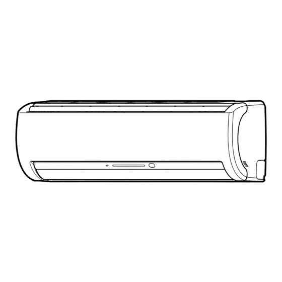
Ilmalämpöpumppujen myynti, huolto ja asennus: Jäähdytinpalvelu RefGroup Oy. 4. CONSTRUCTION VIEWS 4-1. Indoor Unit RAS-B10EKVP-E RAS-B13EKVP-E RAS-B16EKVP-E Parts name of remote control WH-H03JE Lue lisää nettisivuiltamme: www.ilmalämpöpumput.com – 15 –... - Page 16 Ilmalämpöpumppujen myynti, huolto ja asennus: Jäähdytinpalvelu RefGroup Oy. 4-2. Outdoor Unit RAS-10EAVP-E, RAS-13EAVP-E, RAS-16EAVP-E Lue lisää nettisivuiltamme: www.ilmalämpöpumput.com – 16 –...
-
Page 17: Wiring Diagram
RAS-10EAVP-E, RAS-13EAVP-E, RAS-16EAVP-E Color Identification WHITE BLACK BLUE BROWN ORANGE PURPUL YELLOW 5-2. Indoor Unit GRAY PINK RAS-B10EKVP-E, RAS-B13EKVP-E, RAS-B16EKVP-E GRN& GREEN& YELLOW INDOOR 1 2 3 4 TERMINAL BLOCK 1 2 3 4 Heat exchanger Ion electrode GRN & YEL... -
Page 18: Specifications Of Electrical Parts
Ilmalämpöpumppujen myynti, huolto ja asennus: Jäähdytinpalvelu RefGroup Oy. 6. SPECIFICATIONS OF ELECTRICAL PARTS 6-1. Indoor Unit RAS-B10EKVP-E, RAS-B13EKVP-E, RAS-B16EKVP-E Parts name Type Specifications Fan motor (for indoor) MF-280-30-5 DC280–340V, 30W Room temp. sensor ( – ) 10kΩ at 25°C (TA-sensor) Heat exchanger temp. -
Page 19: Refrigerant Cycle Diagram
Ilmalämpöpumppujen myynti, huolto ja asennus: Jäähdytinpalvelu RefGroup Oy. 7. REFRIGERANT CYCLE DIAGRAM 7-1. Refrigerant Cycle Diagram RAS-B10EKVP-E/RAS-10EAVP-E Temp. measurement INDOOR UNIT Indoor heat exchanger Cross flow fan Max. : 25m Chargeless : 15m Pressure measurement Deoxidized copper pipe Charge : 20g/m Gauge attaching port Outer dia. - Page 20 Ilmalämpöpumppujen myynti, huolto ja asennus: Jäähdytinpalvelu RefGroup Oy. RAS-B13EKVP-E/RAS-13EAVP-E RAS-B16EKVP-E/RAS-16EAVP-E Temp. measurement INDOOR UNIT Indoor heat exchanger Cross flow fan Max. : 25m Chargeless : 15m Pressure measurement Deoxidized copper pipe Charge : 20g/m Gauge attaching port Outer dia. : 6.35mm (16 to 25m) Vacuum pump connecting port Thickness : 0.8mm...
-
Page 21: Operation Data
Ilmalämpöpumppujen myynti, huolto ja asennus: Jäähdytinpalvelu RefGroup Oy. 7-2. Operation Data <Cooling> Temperature Heat exchanger Model Standard Compressor condition (°C) pipe temp. Indoor fan Outdoor fan name pressure revolution mode mode RAS- P (MPa) (rps) Indoor Outdoor T1 (°C) T2 (°C) B10EKVP-E 0.9 to 1.1 13 to 15... -
Page 22: Control Block Diagram
Ilmalämpöpumppujen myynti, huolto ja asennus: Jäähdytinpalvelu RefGroup Oy. 8. CONTROL BLOCK DIAGRAM 8-1. Indoor Unit RAS-B10EKVP-E, RAS-B13EKVP-E, RAS-B16EKVP-E Indoor Unit Control Unit M.C.U Louver Functions Motor Heat Exchanger Sensor(Tc) • Cold draft preventing Function Room Temperature Sensor(Ta) Louver Motor • 3-minute Delay at Restart for Compressor... - Page 23 Ilmalämpöpumppujen myynti, huolto ja asennus: Jäähdytinpalvelu RefGroup Oy. 8-2. Outdoor Unit (Inverter Assembly) RAS-10EAVP-E, RAS-13EAVP-E, RAS-16EKVP-E Lue lisää nettisivuiltamme: www.ilmalämpöpumput.com – 23 –...
-
Page 24: Operation Description
Ilmalämpöpumppujen myynti, huolto ja asennus: Jäähdytinpalvelu RefGroup Oy. 9. OPERATION DESCRIPTION • Detection of inverter input current and current 9-1. Outline of Air Conditioner Control release operation This air conditioner is a capacity-variable type air • Over-current detection and prevention operation conditioner, which uses DC motor for the indoor fan to IGBT module (Compressor stop function) motor and the outdoor fan motor. - Page 25 Ilmalämpöpumppujen myynti, huolto ja asennus: Jäähdytinpalvelu RefGroup Oy. 9-2. Operation Description Contents Page Basic operation ................26 1) Operation control ..................... 26 2) Cooling/Heating operation ................26 3) AUTO operation ....................27 4) DRY operation ....................27 Indoor fan motor control ..............28 <In cooling operation>...
-
Page 26: Basic Operation
Ilmalämpöpumppujen myynti, huolto ja asennus: Jäähdytinpalvelu RefGroup Oy. Item Operation flow and applicable data, etc. Description 1. Basic 1) Operation control 1) The operation conditions are operation selected by the remote controller as Receiving the user’s operation condition setup, the opera- shown in the left. -
Page 27: Auto Operation
Ilmalämpöpumppujen myynti, huolto ja asennus: Jäähdytinpalvelu RefGroup Oy. Item Operation flow and applicable data, etc. Description 1. Basic operation 3) AUTO operation 1) Detects the room temperature (Ta) when the operation started. Selection of operation mode 2) Selects an operation mode from As shown in the following figure, the operation starts by Ta in the left figure. -
Page 28: Indoor Fan Motor Control
Ilmalämpöpumppujen myynti, huolto ja asennus: Jäähdytinpalvelu RefGroup Oy. Item Operation flow and applicable data, etc. Description 2. Indoor fan <In cooling operation> motor control (This operation controls the fan speed at indoor unit side.) * Symbols : Ultra High The indoor fan (cross flow fan) is operated by the phase- : High control induction motor. -
Page 29: In Heating Operation
Ilmalämpöpumppujen myynti, huolto ja asennus: Jäähdytinpalvelu RefGroup Oy. Item Operation flow and applicable data, etc. Description 2. Indoor fan <In heating operation> 1) When setting the fan speed to motor control L, L+, M, M+ or H on the remote controller, the operation is HEAT ON performed with the constant... -
Page 30: Outdoor Fan Motor Control
Ilmalämpöpumppujen myynti, huolto ja asennus: Jäähdytinpalvelu RefGroup Oy. Item Operation flow and applicable data, etc. Description 3. Outdoor fan The blowing air volume at the outdoor unit side is con- 1) The operation command sent motor control trolled. from the remote controller is processed by the indoor unit Receiving the operation command from the controller of controller and transferred to the... -
Page 31: Capacity Control
Ilmalämpöpumppujen myynti, huolto ja asennus: Jäähdytinpalvelu RefGroup Oy. Item Operation flow and applicable data, etc. Description 4. Capacity The cooling or heating capacity depending on the load is 1) The difference between set control adjusted. temperature on remote controller (Ts) and room temperature (Ta) According to difference between the setup value of tem- is calculated. -
Page 32: Release Protective Control
Ilmalämpöpumppujen myynti, huolto ja asennus: Jäähdytinpalvelu RefGroup Oy. Item Operation flow and applicable data, etc. Description 6. Release <In cooling/dry operation> 1) When temperature of the indoor protective (Prevent-freezing control for indoor heat exchanger) heat exchanger drops below control by 5°C, the compressor speed is In cooling/dry operation, the sensor of indoor heat ex- temperature of... -
Page 33: Quick Heating Control
Ilmalämpöpumppujen myynti, huolto ja asennus: Jäähdytinpalvelu RefGroup Oy. Item Operation flow and applicable data, etc. Description 7. Quick heating This function quickens the starting of heating operation When the following conditions are control when indoor/outdoor temperature is low. satisfied, winding is heated by output (Available only in heating operation) varied by the outdoor heat ex- changer temperature. -
Page 34: Louver Control
Ilmalämpöpumppujen myynti, huolto ja asennus: Jäähdytinpalvelu RefGroup Oy. Item Operation flow and applicable data, etc. Description 9. Louver control This function controls the air direction of the indoor unit. 1) Louver • The position is automatically controlled according to the operation position mode (COOL/HEAT). -
Page 35: Eco Operation
Ilmalämpöpumppujen myynti, huolto ja asennus: Jäähdytinpalvelu RefGroup Oy. Item Operation flow and applicable data, etc. Description 10. ECO When pushing [ECO] button on the remote controller, a quiet operation and mild operation is performed by reducing the fan speed and the compressor speed. -
Page 36: Temporary Operation
Ilmalämpöpumppujen myynti, huolto ja asennus: Jäähdytinpalvelu RefGroup Oy. Item Operation flow and applicable data, etc. Description 11. Temporary Pushing [RESET] button starts the temporary operation 1) When pushing [RESET] button, the operation of [AUTO] operation. When keeping [RESET] button temporary [AUTO] operation starts. pushed for 10 seconds or more, the temporary [COOL] 2) When keeping [RESET] button pushed operation is performed. -
Page 37: Air Purifying Control
Ilmalämpöpumppujen myynti, huolto ja asennus: Jäähdytinpalvelu RefGroup Oy. Item Operation flow and applicable data, etc. Description 12. Air This function generates nagative ion while cleaning the Operation button purifying air in the room. Present control PURE button Air conditioner If air purifier-ON signal is received while the air condi- status tioner stops, the air purifier starts operation, and if it is Stop... -
Page 38: Air Purifying Control [Detection Of Abnormality]
Ilmalämpöpumppujen myynti, huolto ja asennus: Jäähdytinpalvelu RefGroup Oy. Item Operation flow and applicable data, etc. Description 1. Purpose 12. Air purifying The air purifying control function is to alert Purifying operation control the user to trouble in the ionizing or air purifying operation. -
Page 39: Pulse Motor Valve (Pmv) Control
Ilmalämpöpumppujen myynti, huolto ja asennus: Jäähdytinpalvelu RefGroup Oy. Item Operation flow and applicable data, etc. Description 14. Pulse Motor This function controls throttle amount of the refrigerant in 1) When starting the operation, move valve the refrigerating cycle. the valve once until it fits to the (PMV) stopper. -
Page 40: Clean Operation
Ilmalämpöpumppujen myynti, huolto ja asennus: Jäähdytinpalvelu RefGroup Oy. Item Operation flow and applicable data, etc. Description 15. Clean 1. Purpose operation The clean operation is to minimize Unit now performing cooling or dry operation the growth of mold, bacteria etc. by running the fan and drying so as to keep the inside of the air condi- Push "stop"... -
Page 41: Clean Operation Release
Ilmalämpöpumppujen myynti, huolto ja asennus: Jäähdytinpalvelu RefGroup Oy. Item Operation flow and applicable data, etc. Description 16. Clean Setting the clean operation release operation release * J04 will be near the Add J04 of the indoor P.C. board MUC so take steps to assembly. -
Page 42: Select Switch On Remote Controller
Ilmalämpöpumppujen myynti, huolto ja asennus: Jäähdytinpalvelu RefGroup Oy. Item Description Operation flow and applicable data, etc. 17. Select 1. Purpose switch on Push the operation button This operation is to operate only remote on the remote controller. one indoor unit using one remote controller controller. -
Page 43: Auto Restart Function
Ilmalämpöpumppujen myynti, huolto ja asennus: Jäähdytinpalvelu RefGroup Oy. 9-3. Auto Restart Function 9-3-1. How to Set the Auto Restart Function To set the auto restart function, proceed as follows: This indoor unit is equipped with an automatic restarting function which allows the unit to restart The power supply to the unit must be on ;... -
Page 44: How To Cancel The Auto Restart Function
Ilmalämpöpumppujen myynti, huolto ja asennus: Jäähdytinpalvelu RefGroup Oy. 9-3-2. How to Cancel the Auto Restart Function To cancel auto restart function, proceed as follows : Repeat the setting procedure : the unit receives the signal and beeps three times. The unit will be required to be turned on with the remote controller after the main power supply is turned off. •... -
Page 45: Remote Controller And Its Fuctions
Ilmalämpöpumppujen myynti, huolto ja asennus: Jäähdytinpalvelu RefGroup Oy. 9-5. Remote Controller and Its Fuctions 9-5-1. Parts Name of Remote Controller a Infrared signal transmitter n Automatic operation button (AUTO) Transmits signals to the indoor unit. Press this button to operate the air conditioner automatically. -
Page 46: Name And Functions Of Indications On Remote Controller
Ilmalämpöpumppujen myynti, huolto ja asennus: Jäähdytinpalvelu RefGroup Oy. 9-5-2. Name and Functions of Indications on Remote Controller [Display] All indicators, except for the clock time indicator, are displayed by pressing the button. a Transmission mark This transmission mark ( ) indicates when the remote controller transmits signals to the indoor unit. b Mode indicator b h j Indicates the current operation mode. -
Page 47: Hi-Power Mode
Ilmalämpöpumppujen myynti, huolto ja asennus: Jäähdytinpalvelu RefGroup Oy. 9-6. Hi-POWER Mode ([Hi-POWER] button on the remote controller is pushed.) When [Hi-POWER] button is pushed while the indoor unit is in Auto, Cooling or Heating operation, Hi-POWER mark is indicated on the display of the remote controller and the unit operates as follows. -
Page 48: Installation Procedure
Ilmalämpöpumppujen myynti, huolto ja asennus: Jäähdytinpalvelu RefGroup Oy. 10. INSTALLATION PROCEDURE 10-1.Installation Diagram of Indoor and Outdoor Units For the rear left and left 47 mm or more piping Hook Installation Wall Hook plate 140 mm or more 74 mm or Insert the cushion between more Hook... -
Page 49: Optional Installation Parts
Refrigerant piping Liquid side Gas side Indoor unit name (Outer diameter) (Outer diameter) 1 ea. RAS-B10EKVP-E, B13EKVP-E 6.35 mm 9.52 mm RAS-B16EKVP-E 6.35 mm 12.7 mm Shield pipe (for extension drain hose) (polyethylene foam, 6 mm thick) Attachment bolt arrangement of outdoor unit Elongated drain •... - Page 50 Ilmalämpöpumppujen myynti, huolto ja asennus: Jäähdytinpalvelu RefGroup Oy. Installation/Service Tools Changes in the product and components In air conditioners using R410A, in order to prevent any other refrigerant from being accidentally charged, the service port diameter size of the outdoor unit control valve (3 way valve) has been changed. (1/2 UNF 20 threads per inch) •...
-
Page 51: Installation Of Indoor Unit
Ilmalämpöpumppujen myynti, huolto ja asennus: Jäähdytinpalvelu RefGroup Oy. 10-3. Installation of Indoor Unit Installation Location • A place which provides enough space around the indoor unit as shown in the diagram. • A place where there are no obstacles near the air inlet and outlet. •... -
Page 52: Electrical Work
Ilmalämpöpumppujen myynti, huolto ja asennus: Jäähdytinpalvelu RefGroup Oy. Mounting the installation plate Anchor bolt holes a Installation plate Pipe hole Pipe hole g Mounting screw Indoor unit When the installation plate is directly mounted on the wall Securely fit the installation plate onto the wall by screws with the upper and lower catches, that hold the indoor unit, facing out. To mount the installation plate on a concrete wall use anchor bolts. - Page 53 Ilmalämpöpumppujen myynti, huolto ja asennus: Jäähdytinpalvelu RefGroup Oy. CAUTION • This appliance can be connected to a main circuit breaker in either of the following two ways. (1) Connection to fixed wiring: A switch or circuit breaker which disconnects all poles and has a contact separation of at least 3 mm must be incorporate in the fixed wiring.
-
Page 54: Piping And Drain Hose Installation
Ilmalämpöpumppujen myynti, huolto ja asennus: Jäähdytinpalvelu RefGroup Oy. Piping and Drain Hose Installation Piping and drain hose forming • Since condensation results in machine trouble, make sure to insulate both the connecting pipes separately. (Use polyethylene foam as insulating material.) Rear right Rear left Bottom left... - Page 55 Ilmalämpöpumppujen myynti, huolto ja asennus: Jäähdytinpalvelu RefGroup Oy. In case of right or left piping • After making slits on the front panel with a knife or similar tool, cut them out with a pair of nippers or an equivalent tool. Slit In case of bottom right or bottom left piping •...
-
Page 56: Indoor Unit Installation
Ilmalämpöpumppujen myynti, huolto ja asennus: Jäähdytinpalvelu RefGroup Oy. Indoor Unit Installation Pass the pipe through the hole in the wall, and hook the indoor unit on the installation plate at the upper hooks. Swing the indoor unit to right and left to confirm that it is firmly hooked on the installation plate. While pressing the indoor unit onto the wall, hook it at the lower part on the installation plate. -
Page 57: Installation Of Outdoor Unit
Ilmalämpöpumppujen myynti, huolto ja asennus: Jäähdytinpalvelu RefGroup Oy. 10-4. Installation of Outdoor Unit Installation Location • A place which provides enough space around the outdoor unit as shown in the diagram. • A place which can bear the weight of the outdoor unit and does not allow an increase in noise level and vibration. •... -
Page 58: Refrigerant Piping Connection
Ilmalämpöpumppujen myynti, huolto ja asennus: Jäähdytinpalvelu RefGroup Oy. Refrigerant Piping Connection Flaring Cut the pipe with a pipe cutter. Warp Roughness Obliquity Insert a flare nut into the pipe, and flare the pipe. • Projection margin in flaring: A (Unit: mm) Rigid (Clutch type) Outer diameter of copper pipe R410A tool used... - Page 59 Ilmalämpöpumppujen myynti, huolto ja asennus: Jäähdytinpalvelu RefGroup Oy. Evacuating After the piping has been connected to the indoor unit, perform the air purge. AIR PURGE Evacuate the air in the connecting pipes and in the indoor unit using a vacuum pump. Do not use the refrigerant in the outdoor uni t. For details, see the vacuum pump manual.
- Page 60 Ilmalämpöpumppujen myynti, huolto ja asennus: Jäähdytinpalvelu RefGroup Oy. Packed valve handling precautions • Open the valve stem all the way; but do not try to open it beyond the stopper. • Securely tighten the valve stem cap with torque in the following table: Gas side 50 to 62 N·m Hexagon wrench...
- Page 61 Ilmalämpöpumppujen myynti, huolto ja asennus: Jäähdytinpalvelu RefGroup Oy. 10-5.Test Operation Valve cover Gas Leak Test • Check the flare nut connections for gas leaks with a Check places for gas leak detector and/or soapy water. indoor unit Electric parts cover Check places for outdoor unit Test Operation To test the system, press and hold RESET button for 10 sec.
-
Page 62: How To Diagnose The Trouble
Ilmalämpöpumppujen myynti, huolto ja asennus: Jäähdytinpalvelu RefGroup Oy. 11. HOW TO DIAGNOSE THE TROUBLE The pulse motor circuits are mounted to both indoor Table 11-1 and outdoor units. Therefore, diagnose troubles Troubleshooting Procedure Page according to the trouble diagnosis procedure as described below. - Page 63 Ilmalämpöpumppujen myynti, huolto ja asennus: Jäähdytinpalvelu RefGroup Oy. Precautions when inspecting the control section of the outdoor unit NOTE : A large-capacity electrolytic capacitor is used in the outdoor unit controller (inverter). Therefore, if the power supply is turned off, charge (charging voltage DC280 to 380V) remains and discharging takes a lot of time. After turning off the power source, if touching the charging section before discharging, an electrical shock may be caused.
-
Page 64: First Confirmation
Ilmalämpöpumppujen myynti, huolto ja asennus: Jäähdytinpalvelu RefGroup Oy. 11-1. First Confirmation 11-1-1. Confirmation of Power Supply Confirm that the power breaker operates (ON) normally. 11-1-2. Confirmation of Power Voltage Confirm that power voltage is AC 220–230–240 ± 10%. If power voltage is not in this range, the unit may not operate normally. -
Page 65: Primary Judgment
Ilmalämpöpumppujen myynti, huolto ja asennus: Jäähdytinpalvelu RefGroup Oy. 11-2. Primary Judgment To diagnose the troubles, use the following methods. (1) Judgment by flashing LED of indoor unit (2) Self-diagnosis by service check remote controller (3) Judgment of trouble by every symptom Firstly use the method (1) for diagnosis. - Page 66 Ilmalämpöpumppujen myynti, huolto ja asennus: Jäähdytinpalvelu RefGroup Oy. 11-4. Self-Diagnosis by Remote Controller (Check Code) (1) If the indicators light as shown B to E in Table 11-3-1, excute the self-diagnosis by the remote controller. (2) When the remote controller is set to the service mode, the indoor controller diagnoses the operation condition and indicate the information of the self-diagnosis on the display of the remote controller with the check codes.
- Page 67 Ilmalämpöpumppujen myynti, huolto ja asennus: Jäähdytinpalvelu RefGroup Oy. 11-4-2. Caution at Servicing (1) After servicing, push the START/STOP button to return to the normal mode. (2) After servicing by the check code, turn off breaker of the power supply, and turn on breaker of the power supply again so that memory in the microcomputer returns the initial status.
- Page 68 Ilmalämpöpumppujen myynti, huolto ja asennus: Jäähdytinpalvelu RefGroup Oy. Block distinction Operation of diagnosis function Judgment and action Check Check Block Cause of operation conditioner Remarks code code status Outdoor P.C. Inverter over-current All off Displayed when Even if trying operation again, all board protective circuit error is detected.
-
Page 69: Judgment Of Trouble By Every Symptom
Ilmalämpöpumppujen myynti, huolto ja asennus: Jäähdytinpalvelu RefGroup Oy. 11-5. Judgment of Trouble by Every Symptom 11-5-1. Indoor Unit (Including Remote Controller) (1) Power is not turned on (Does not operate entirely) <Primary check> 1. Is the supply voltage normal? Operation 2. - Page 70 Ilmalämpöpumppujen myynti, huolto ja asennus: Jäähdytinpalvelu RefGroup Oy. (3) Only the indoor motor fan does not operate <Primary check> 1. Is it possible to detect the power supply voltage (AC220–240V) between on the terminal block? 2. Does the indoor fan motor operate in cooling operation? (In heating operation, the indoor fan motor does not operate for approximately 10 minutes after it is turned on, to prevent a cold air from blowing in.) Turn off power...
- Page 71 Ilmalämpöpumppujen myynti, huolto ja asennus: Jäähdytinpalvelu RefGroup Oy. (4) Indoor fan motor automatically starts to rotate by turning on power supply <Cause> The IC is built in the indoor fan motor. Therefore the P.C. board is also mounted to inside of the motor. If the P.C.
- Page 72 Ilmalämpöpumppujen myynti, huolto ja asennus: Jäähdytinpalvelu RefGroup Oy. (5) Troubleshooting for remote controller <Primary check> Check that A or B selected on the main unit is matched with A or B selected on the remote controller. The unit does not beep at all. Push the START/STOP button.
- Page 73 Ilmalämpöpumppujen myynti, huolto ja asennus: Jäähdytinpalvelu RefGroup Oy. 11-5-2. Wiring Failure (Interconnecting and Serial Signal Wire) (1) Outdoor unit does not operate 1) Is the voltage between of the indoor terminal block varied? Confirm that transmission from indoor unit to outdoor unit is correctly performed based upon the following diagram.
- Page 74 Ilmalämpöpumppujen myynti, huolto ja asennus: Jäähdytinpalvelu RefGroup Oy. 11-6. Check Code 1C (Miswiring in indoor/outdoor units) and 1E <Check procedure> Gas leakage, Discharge temp. error, disconnection of TS/TC gas leakage sensors (Check code 02, 1C) (Check code 03, 1E) Valve drive check Is coil of the pulse motor valve Set it correctly.
-
Page 75: Troubleshooting
Ilmalämpöpumppujen myynti, huolto ja asennus: Jäähdytinpalvelu RefGroup Oy. 11-7. Troubleshooting 11-7-1. How to Check Whether the Air Purifier is Good or Not Turn off the power breaker once, and turn on again after 10 seconds. Does the OPERATION indicator flash? To item “Power supply is not turned on”... - Page 76 Ilmalämpöpumppujen myynti, huolto ja asennus: Jäähdytinpalvelu RefGroup Oy. 11-7-2. How to Check Whether the Minus Ion Generator is Good or Not Turn off the power breaker once, and turn on again after 10 seconds. Does the OPERATION indicator flash? To item “Power supply is not turned on” Turn off the power breaker and remove CN34 (Micro switch connector).
-
Page 77: How To Diagnose Trouble In Outdoor Unit
Ilmalämpöpumppujen myynti, huolto ja asennus: Jäähdytinpalvelu RefGroup Oy. 11-8. How to Diagnose Trouble in Outdoor Unit 11-8-1. Summarized Inner Diagnosis of Inverter Assembly Table 11-8-1 Diagnosis/Process flowchart Item Contents Summary Preparation Turn “OFF” the power supply breaker, and remove 3P connector which connects Remove connector of... - Page 78 Ilmalämpöpumppujen myynti, huolto ja asennus: Jäähdytinpalvelu RefGroup Oy. Diagnosis/Process flowchart Item Contents Summary Check Check winding resistance between phases of compres- sor, and resistance between outdoor frames by using a tester. → OK if 10MΩ or more • Is not grounded. Replace control board assembly.
- Page 79 Ilmalämpöpumppujen myynti, huolto ja asennus: Jäähdytinpalvelu RefGroup Oy. (3) Check procedures Table 11-9-1 Procedure Check points Causes Turn off the power supply breaker Check whether or not the fuse Impulse voltage was applied or the and remove the P.C. board (F01) is blown.
- Page 80 Ilmalämpöpumppujen myynti, huolto ja asennus: Jäähdytinpalvelu RefGroup Oy. 11-9-2. P.C. Board Layout +12V [1] Sensor characteristic table TD : Discharge temp. sensor TA : Room temp. sensor TC : Heat exchanger temp. sensor TO : Outdoor temp. sensor TA, TC, TO, TE, TS TE : Outdoor heat exchanger temp.
- Page 81 Ilmalämpöpumppujen myynti, huolto ja asennus: Jäähdytinpalvelu RefGroup Oy. 11-9-3. Indoor Unit (Other Parts) Part name Checking procedure Room temp. (TA) sensor Disconnect the connector and measure the resistance value with tester. Heat exchanger (TC) sensor (Normal temp.) Temperature 10°C 20°C 25°C 30°C 40°C...
- Page 82 Ilmalämpöpumppujen myynti, huolto ja asennus: Jäähdytinpalvelu RefGroup Oy. 11-9-5. Checking Method for Each Part Part name Checking procedure Electrolytic capacitor 1. Turn OFF the power supply breaker. (For boost, smoothing) 2. Discharge all three capacitors completely. 3. Check that safety valve at the bottom of capacitor is not broken. 4.
-
Page 83: How To Simply Judge Whether Outdoor Fan Motor Is Good Or Bad
Ilmalämpöpumppujen myynti, huolto ja asennus: Jäähdytinpalvelu RefGroup Oy. 11-10. How to Simply Judge Whether Outdoor Fan Motor is Good or Bad 1. Symptom • Outdoor fan motor does not rotate. • Outdoor fan motor stops within several tens seconds though it started rotating. •... -
Page 84: How To Replace The Main Parts
Ilmalämpöpumppujen myynti, huolto ja asennus: Jäähdytinpalvelu RefGroup Oy. 12. HOW TO REPLACE THE MAIN PARTS WARNING • Since high voltages pass through the electrical parts, turn off the power without fail before proceeding with the repairs. Electric shocks may occur if the power plug is not disconnected. •... - Page 85 Ilmalämpöpumppujen myynti, huolto ja asennus: Jäähdytinpalvelu RefGroup Oy. Part name Procedures Remarks Front panel 4 ) Push “ ” part under the front panel and remove hooks of the front panel from the installation plate. Pull here Installation plate Push here Push here Front panel Push...
- Page 86 Ilmalämpöpumppujen myynti, huolto ja asennus: Jäähdytinpalvelu RefGroup Oy. Part name Procedures Remarks " 1) Follow to the procedure in the item !. High voltage generator 2) Remove the drain guide. Connector Drain guide Air ionizer 3) To remove the air ionizer from the back body, Push the pull it toward you while pressing down on its left claw here...
- Page 87 Ilmalämpöpumppujen myynti, huolto ja asennus: Jäähdytinpalvelu RefGroup Oy. Part name Procedures Remarks " High voltage <How to assemble the high voltage generator> generator 1) Insert the high voltage generator straight into the evaporator, and secure it using the fixing screw. Check whether the leads have been completely...
- Page 88 Ilmalämpöpumppujen myynti, huolto ja asennus: Jäähdytinpalvelu RefGroup Oy. Part name Procedures Remarks " Electric parts 1) Follow the procedure up to 4) in above. Lead wire box assembly 2) Remove screw of earth lead attached to the end cover plate of the evaporator. 3) Remove the lead wire cover, and remove connector (5P) for the fan motor and connector (5P) for the louver motor from the electric parts...
- Page 89 Ilmalämpöpumppujen myynti, huolto ja asennus: Jäähdytinpalvelu RefGroup Oy. Part name Procedures Remarks Horizontal 1) Remove shaft of the horizontal louver louver from the back body. (First remove the left shaft, and then remove other shafts while sliding the horizontal louver leftward.) Slide the horizontal louver leftward...
- Page 90 Ilmalämpöpumppujen myynti, huolto ja asennus: Jäähdytinpalvelu RefGroup Oy. Part name Procedures Remarks & Bearing 1) Follow to the procedure in the items 2) Remove the two fixing screws used to secure the left edge panel of the heat exchanger, and Screw remove the two screws used to secure the Bearing...
- Page 91 Ilmalämpöpumppujen myynti, huolto ja asennus: Jäähdytinpalvelu RefGroup Oy. Part name Procedures Remarks Fan motor 1) Follow to the procedure in the item 2) Loosen the set screw of the cross flow fan. 3) Remove two fixing screws of the motor band (Right), and then remove the motor band (Right).
- Page 92 Ilmalämpöpumppujen myynti, huolto ja asennus: Jäähdytinpalvelu RefGroup Oy. Part name Procedures Remarks Cross flow <Caution at reassembling> a) At assembling work of the bearing base, check that the drain pipe is surely incorporated in the back body. (Otherwise, water leak is caused.) Drain pipe Bearing base b) To incorporate the fan motor, remove the fan...
- Page 93 Ilmalämpöpumppujen myynti, huolto ja asennus: Jäähdytinpalvelu RefGroup Oy. 12-2. Microcomputer Part name Procedure Remarks Common procedure 1) Turn the power supply off to stop the Replace terminal block, operation of air-conditioner. microcomputer assembly and the P.C. board assembly. 2) Remove the front panel. •...
- Page 94 Ilmalämpöpumppujen myynti, huolto ja asennus: Jäähdytinpalvelu RefGroup Oy. 12-3. Outdoor Unit Part name Procedures Remarks Common 1. Detachment Upper cabinet procedure NOTE : Water proof Wear gloves for this job. cover Otherwise, you may injure your hands on the parts, etc. 1) Stop operation of the air conditioner, and turn off the main switch of the breaker for air condi- tioner.
- Page 95 Ilmalämpöpumppujen myynti, huolto ja asennus: Jäähdytinpalvelu RefGroup Oy. Part name Procedures Remarks Front cabinet 1. Detachment 1) Perform step 1 in 2) Remove the fixing screws (ST1TØ4 x 8l l l l l 2 pcs.) used to secure the front cabinet and inverter cover, the screws (ST1TØ4 x 8l l l l l 3 pcs.) used to secure the front cabinet at the bottom, and the fixing screws (ST1TØ4 x 8l l l l l 2 pcs.) used to...
- Page 96 Ilmalämpöpumppujen myynti, huolto ja asennus: Jäähdytinpalvelu RefGroup Oy. Part name Procedure Remarks " Inverter 1) Perform work of item 1 in Inverter cover assembly l l l l l P . C. board 2) Remove screw (ST1TØ4 x 8 2 pcs.) of the upper (Soldered surface) part of the front cabinet.
- Page 97 Ilmalämpöpumppujen myynti, huolto ja asennus: Jäähdytinpalvelu RefGroup Oy. Part name Procedures Remarks Control board 1) Disconnect the leads and connectors connected assembly to the other parts from the control board assem- CN603 bly. CN601 CN600 CN701 1) Leads CN700 CN602 CN300 •...
- Page 98 Ilmalämpöpumppujen myynti, huolto ja asennus: Jäähdytinpalvelu RefGroup Oy. Part name Procedures Remarks Side cabinet 1. Side cabinet (right) " 1) Perform step 1 in and all the steps in 2) Remove the fixing screw (ST1TØ4 x 8l l l l l 5 pcs.) used for securing the side cabinet to the bottom plate and valve fixing panel.
- Page 99 Ilmalämpöpumppujen myynti, huolto ja asennus: Jäähdytinpalvelu RefGroup Oy. Part name Procedures Remarks " Fan motor 1) Perform work of item 1 of 2) Remove the flange nut fixing the fan motor and Propeller fan the propeller. Fan motor • Flange nut is loosened by turning clockwise. (To tighten the flange nut, turn counterclock- wise.) 3) Remove the propeller fan.
- Page 100 Ilmalämpöpumppujen myynti, huolto ja asennus: Jäähdytinpalvelu RefGroup Oy. Part name Procedures Remarks Electronic 1. Detachment " expansion 1) Perform step 1 in , all the steps in and 1 in valve coil Coil anti-turn 2) Remove the coil by pulling it up from the elec- lock tronic control valve body.
- Page 101 Ilmalämpöpumppujen myynti, huolto ja asennus: Jäähdytinpalvelu RefGroup Oy. Part name Procedures Remarks TE sensor • Attachment (outdoor heat With the leads pointing downward and the sensor exchanging leads pointing in the direction shown in the figure, temperature install the sensor onto the straight pipe part of the Detail A Arrow D sensor)
- Page 102 Ilmalämpöpumppujen myynti, huolto ja asennus: Jäähdytinpalvelu RefGroup Oy. Part name Procedure Remarks Replacement of 1) Cut the sensor 100 mm longer than old one. temperature 2) Cut the protective tube after pulling out it Cutting here sensor for (200 mm). Thermal Connector sensor part...
- Page 103 Ilmalämpöpumppujen myynti, huolto ja asennus: Jäähdytinpalvelu RefGroup Oy. MCC-5009 Lue lisää nettisivuiltamme: www.ilmalämpöpumput.com – 103 –...
-
Page 104: Exploded Views And Parts List
Ilmalämpöpumppujen myynti, huolto ja asennus: Jäähdytinpalvelu RefGroup Oy. 13. EXPLODED VIEWS AND PARTS LIST 13-1. Indoor Unit (1) 221 222 224 Location No. Part Description Location No. Part Description 43005611 43049674 SPRING, SUCTION (B16EKVP-E) PANEL ASS’Y, FRONT 43047331 PIPE, DELIVERY 43005610 GRILLE, AIR INLET 43044788... - Page 105 Ilmalämpöpumppujen myynti, huolto ja asennus: Jäähdytinpalvelu RefGroup Oy. Indoor Unit (2) Location No. Part Description 4306A123 TERMINAL BLOCK, 2P 43062189 COVER, E-PARTS 43050382 SENSOR, TC (F6) 43050400 SENSOR, TA 4306S484 P.C. BOARD ASS’Y, WRS-LED 43051343 SW-MICRO ASS ’ 4306S609 PC BOARD ASS Y (B10EKVP-E) ’...
- Page 106 VALVE, PACKED, 9.52 (10EAVP–E, 13EAVP-E) 43032441 NIPPLE, DRAIN 43046393 VALVE, PACKED,12.7 (16EAVP-E) 43089160 CAP, WATERPROOF 43147196 BONNET, 1/4 IN 4301P703 MARK, TOSHIBA 43047401 BONNET, 3/8 IN (10EAVP–E, 13EAVP-E) 4301P702 MARK, DAISEIKAI 43147195 BONNET, 1/2 IN (16EAVP-E) 43049749 RUBBER, CUSHION 43047653 NUT, FLARE, 6.35...
- Page 107 Ilmalämpöpumppujen myynti, huolto ja asennus: Jäähdytinpalvelu RefGroup Oy. 13-3. P.C. Board Layout Location No. Part Description 43050412 SENSOR, TE 43050413 SENSOR, TS 43050415 SENSOR, TO 43062228 BASE, PC BOARD 43160469 TERMINAL BLOCK, 6P 43050354 SENSOR, TD 4306S612 PC BOARD ASSY, MCC-5009 Lue lisää...
- Page 108 Ilmalämpöpumppujen myynti, huolto ja asennus: Jäähdytinpalvelu RefGroup Oy. Appendix Cord Heater Installation Work Applicable Models: RAS-10EAVP-E, RAS-13EAVP-E, RAS-16EAVP-E 1. Required parts for installation work (Recommendation) Part name Q’ty Specifications/Vendor Remarks Cord heater Drain line heaters CSC2 (1.5m, 40W/m) by Flexelec com. Procured locally (Please go to the following URL.) http://www.flexelec.com...
-
Page 109: Appendix
Ilmalämpöpumppujen myynti, huolto ja asennus: Jäähdytinpalvelu RefGroup Oy. Appendix Part name Q’ty Specifications/Vendor Remarks Power cord 2-cores x 0.75mm² or more, H05RN-F Procured locally Thermostat Material: SGCC-Z08, Board thickness: 0.8t Procured locally fixing plate (Drawing attached) PVC tube Inside diameter Ø8 x outside diameter Ø11 x 70 mm Procured locally Shield tube Inside diameter Ø18 x outside diameter Ø26 x 70 mm... - Page 110 Ilmalämpöpumppujen myynti, huolto ja asennus: Jäähdytinpalvelu RefGroup Oy. Appendix 3. Cord heater installation wiring diagram Fuse Thermostat Cord heater * Be sure to connect the fuse and the thermostat to LIVE side of the cord heater. Outdoor unit Earth leakage circuit breaker Power supply for air conditioner Earth leakage circuit breaker Power supply for cord heater...
- Page 111 Ilmalämpöpumppujen myynti, huolto ja asennus: Jäähdytinpalvelu RefGroup Oy. Appendix 4. Cord heater installation work procedure Photo / Explanatory diagram Procedure Remove each cabinet, inverter assembly, motor base assembly, and partition board assembly. * Do not damage the electric parts such as cables, connectors, etc. while this work. Remove the upper cabinet and the valve cover.
- Page 112 Ilmalämpöpumppujen myynti, huolto ja asennus: Jäähdytinpalvelu RefGroup Oy. Appendix Photo / Explanatory diagram Procedure Remove the motor base assembly, partition plate assembly and the sound insulation board. Motor base assembly Related parts / Screws list Partition plate Used screw assembly Part name Screw type Quantity...
- Page 113 Ilmalämpöpumppujen myynti, huolto ja asennus: Jäähdytinpalvelu RefGroup Oy. Appendix Photo / Explanatory diagram Procedure Cord heater installation work Drill a hole on the outdoor unit base plate, and fix the cord heater to the outdoor unit base plate using P-shape clamp.
- Page 114 Ilmalämpöpumppujen myynti, huolto ja asennus: Jäähdytinpalvelu RefGroup Oy. Appendix Photo / Explanatory diagram Procedure Rework the side cabinet (L) to remove part of it. Side cabinet (L) The area to be removed is indicated by the shaded lines in the left figure. After removing part of the side cabinet (L), deburr the edges of the side cabinet (L).
- Page 115 Ilmalämpöpumppujen myynti, huolto ja asennus: Jäähdytinpalvelu RefGroup Oy. Appendix Photo / Explanatory diagram Procedure Assembly Return a set of the refrigeration cycle assembly into the outdoor unit base plate and reassemble sound insulation board, partition plate assembly, fan motor assembly, and side cabinet (R/L) as original. Fix the thermostat fixing plate to the side cabinet (R), built in the inverter assembly, and then connect various cables.
- Page 116 Ilmalämpöpumppujen myynti, huolto ja asennus: Jäähdytinpalvelu RefGroup Oy. Appendix 5. Drawing of thermostat fixing plate 3.4 burring hole (Upward) 3.4 burring hole (Downward) Material: SGCC-Z08, Thickness: 0.8t Lue lisää nettisivuiltamme: www.ilmalämpöpumput.com Appendix-9...
- Page 117 Ilmalämpöpumppujen myynti, huolto ja asennus: Jäähdytinpalvelu RefGroup Oy. Appendix 6. Diagram showing positions φ φ φ φ φ 3.2 mm holes to be additionally drilled in base plate Lue lisää nettisivuiltamme: www.ilmalämpöpumput.com Appendix-10...
- Page 118 Ilmalämpöpumppujen myynti, huolto ja asennus: Jäähdytinpalvelu RefGroup Oy. Lue lisää nettisivuiltamme: www.ilmalämpöpumput.com...
Need help?
Do you have a question about the RAS-B10EKVP-E and is the answer not in the manual?
Questions and answers