
Related Manuals for NorthStar Multi-Function Unit M121

Summary of Contents for NorthStar Multi-Function Unit M121
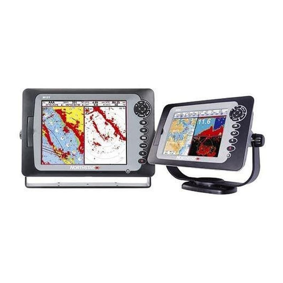
- Page 1 M121/M84 Multi-Function Unit Installation and Operation Manual www.northstarnav.com...
-
Page 2: Table Of Contents
Contents 1 Introduction ...5 1-1 Overview ................... . . 6 1-2 Cleaning and maintenance . - Page 3 10 Sonar fishfinding: Windows ... 42 10-1 Sonar history window - no split ..............42 10-2 Sonar Zoom and Full Screen Zoom displays .
- Page 4 19 Setting up the M121/M84 ... 70 19-1 Setup > System ..................71 19-2 Setup >...
- Page 5 Warning It is your sole responsibility to install and use the instrument and transducer(s) in a manner that will not cause accidents, personal injury or property damage. Always observe safe boating practices. The choice, location, and installation of transducers and other components of the system are critical to the performance of the system as intended.
-
Page 6: Introduction
Navigate to any point or to a waypoint Navigate along a route Projected course: An estimate of progress Tracks: records of where the boat has been GPS receiver status Saving and loading data with a user card Chart data Chart features (built in world chart) -
Page 7: Overview
Radar Overview of the radar The radar window explained Change the radar operation mode Change the radar rotation or motion mode Optimize the quality of the radar window Find range and bearing with VRM/EBL Set up the radar guard zones 1-1 Overview The Northstar M121/M84 is a rugged, highly integrated marine chartplotter and fishfinder. -
Page 8: Plug-In Cards
1-3 Plug-in cards The M121/M84 can use two kinds of C-MAP™ SD-Card plug-in cards: 1. Chart cards have chart details required for navigating in a particular region. When you insert a chart card, the extra details automatically appear on the Chart window. You can plug in up to two chart cards at once. -
Page 9: Removing And Replacing The Display Unit
1-4 Removing and replacing the display unit If the M121/M84 is bracket mounted then it can easily be removed for security. Removing the display unit: 1 Turn the M121/M84 off (see section 2-2) and put the dust cover on. 2 Loosen the knobs on the mounting bracket and lift the unit off the bracket. -
Page 10: Basic Operation
2 Basic Operation Overview of the M121 keys – Go back to an earlier menu or window. In chart mode centers chart at boat’s position. – This is a powerful key that allows you DISPLAY to setup the display the way you want. Main displays can be saved as favorite displays for easy access from the –... - Page 11 Overview of the M84 keys Note: Display refers to ALL windows and the data header/Compass Window refers to a part of the display in which a particular function is shown e.g. The Chart window on a Chart + Sonar display. –...
-
Page 12: Using The Keys
2-1 Using the keys In this manual: Press means to push the key for less than a second. Hold means to hold the key down. The internal beeper beeps when a key is pressed (to adjust the beep volume, see section 19-1). -
Page 13: Turning On And Off / Auto Power
2-2 Turning on and off / auto power Turning on manually If the Instrument is not wired for auto power, press to turn the unit on. If necessary, adjust the display to be easy to read (see section 2-3). WARNING If the Instrument is not wired for auto power then the Instrument does not record engine hours and will not record fuel consumption... -
Page 14: Man Overboard (Mob)
2-4 Man overboard (MOB) The MOB feature saves the boat’s position and then navigates back to this point. WARNING MOB will not work if the Instrument does not have a GPS fix. 1 Press The Instrument stores the boat’s position as a waypoint called MOB. -
Page 15: Simulate Mode
2-6 Simulate mode In Simulate mode, the Instrument ignores data from the GPS antenna and other transducers and sensors and the Instrument generates this data itself. Otherwise, the Instrument functions normally. There are two simulate modes: • Normal: Allows a user to become familiar with the Instrument off the water. - Page 16 To show one of the other windows full-screen, press , select More... and select the window. DISPLAY Press to return from one of these windows to the previous window. Northstar M121/M84 Installation and Operation Manual...
- Page 17 2-7-1 Multi window displays The M121/M84 can show up to four windows at once, for example Chart, Sonar, Gauges and Video: Adding a window to the display Press , select Add window and select a DISPLAY window to add. The M121/M84 automatically rearranges the display to show the new window.
- Page 18 2-7-2 Favorite displays The M121/M84 has a list of commonly used displays, called favorite displays. There can be up to six favorite displays. Each display can have one or more windows plus a data header (see section 2-7-3) and a compass (see section 2-7-4).
- Page 19 2-7-3 Data header The displays can show data at the top, called the data header. When you select a window from the display menu (see section 2-7) the M121/M84 displays an appropriate data header for the window. Each favorite display (see section 2-7-2) has its own data header.
-
Page 20: Navigation: Chart
3 Navigation: Chart The chart window shows the chart, the boat’s position course and navigation data. 3-1 Introduction to navigating The Instrument has two ways of navigating, going straight to a point or following a route. 3-1-1 Navigating to a point When the Instrument is navigating to a point, the chart and highway windows show navigation data:... - Page 21 Going to a point on the chart 1 Switch to a chart window. 2 Move the cursor to the destination point: either use the cursor keys or use Find (see section 3-2-5). 3 Press and select Goto cursor. MENU WARNING Make sure the course does not pass over land or dangerous waters.
-
Page 22: Chart Window
3-2 Chart window To go to the Chart window: • Press and select Chart DISPLAY A typical chart window shows: A Data header. To turn the data off or on or to change what data is displayed (see section 2-7-3) B Compass (see section 2-7-4) C Chart scale (see section 3-2-3) D Boat position (see section 3-2-1) - Page 23 3-2-1 Chart modes The Chart has two modes: Centre on boat mode To switch to centre on boat mode in the chart window, press . The boat is at the centre of the chart. As the boat moves through the water, the chart automatically scrolls to keep the boat in the centre of the chart.
-
Page 24: Distance And Bearing Calculator
To see stored information about nearby symbols press and select Chart info. Then MENU follow step 3 above. 3-2-5 Finding a chart symbol To find and display a chart symbol: 1 Press and select Find. MENU 2 Select the type of symbol: Waypoints, Routes, Ports by name, Ports &... -
Page 25: Projected Course
3-4 Projected course If Projected course is turned on, then the Instrument will display the projected position based on the course over ground (COG), speed and a specified time. To turn Projected course on and off and to set the time, see section 19-2. A Projected position B Boat’s projected course C Boat position... -
Page 26: Video Window
4 Video window The video window shows a picture from a video device, such as a camera. The video window requires a video device to be installed. To select the video window, press select Video. Adjusting the video picture color 1 Press MENU 2 Press... -
Page 27: Navigation: Highway Window
5 Navigation: Highway window The highway window has a bird’s eye view of the boat’s course to a destination: To go to the Highway window, press select More, then select Highway. 6 Navigation: Waypoints A waypoint is a position that you can set on the Instrument chart, for example a fishing spot or a point on a route. -
Page 28: Waypoints Window
6-1 Waypoints window To go to the waypoints window, press select More, then select Waypoints. The waypoints window is a list of the waypoints that have been entered, each with waypoint symbol, name, latitude and longitude, distance and bearing from the boat, type and display option. - Page 29 Editing a waypoint from the waypoints window 1 In the waypoints window, press highlight the waypoint to edit. Press and select Edit. 2 Change the waypoint data (see section 6-2-7). 6-2-4 Displaying a waypoint on the chart This goes to the chart window, and shows the selected waypoint at the centre of the window.
-
Page 30: Navigation: Routes
7 Navigation: Routes A route is a list of waypoints that the boat can navigate along. Routes can be created, changed and deleted. The Instrument can have up to 25 routes. Each route can have up to 50 waypoints. A route can: Start and stop at the same waypoint . - Page 31 1 In the chart window, press New route. 2 The route is given a default name: Change the name if necessary. ii Select OK. 3 To enter the legs of the route: Move the cursor to the start of the route and press ENTER ii A waypoint is created with a default...
- Page 32 5 To remove a waypoint from the route: Select the waypoint to remove. ii Press and select Remove. MENU 6 Repeat this process until the route is finished. 7 Press 8 Display the route on the chart (see section 6-2-3) and check that the route does not cross land or dangerous water.
-
Page 33: Satellites
5° above the horizon to calculate the position. Each time a GPS receiver is turned on, it normally takes about 50 seconds before it outputs the first position. Under some circumstances it will take up to two minutes or longer. -
Page 34: Satellite Window
8-1 Satellite window The satellite window has information about the GPS satellites and GPS position. To go to the satellite window, press select More, then select Satellite. The satellite window shows: 9 Sonar fishfinding: Introduction Sonar functions require an optional sonar transducer to be installed and set up. -
Page 35: Interpreting The Display
The most recent echo appears on the extreme right of the window, with the older echoes being scrolled towards the left, eventually disappearing off the window. The scroll speed depends upon the water depth and scroll speed setting. See sections 19-3 and section 9-2, for more information. - Page 36 The scroll speed can be set by the user to display either a longer history with less fish information or a shorter history with more fish details (see section 19-3). If the boat is anchored, the echoes all come from the same area of bottom. This produces a flat bottom trace on the window.
-
Page 37: Single And Dual Frequency Fishfinding
Shadows Shadows are created around areas where the ultrasonic beam cannot ‘see’. These areas include hollows on the bottom or beside rocks and ledges, where the strong echoes returned off the rocks obscure the weak echoes of the fish and may also create a double bottom trace. Example of shadows A Fish is visible on the window B Fish is hidden by the strong echoes off the... - Page 38 The 200 kHz frequency generates a higher definition pulse which produces little shadow and returns excellent detail over a small area of bottom. Therefore, it gives excellent bottom discrimination capability and is particularly good at showing individual fish, including bottom dwellers. When to use 50 kHz The 50 kHz frequency is particularly suitable for use in deep water, typically greater than 500 ft...
- Page 39 Comparison of the same fish scenario displayed at different frequencies: 1 minute ago 50 kHz display 200/50 kHz display 30 seconds ago 200 kHz display Mixed display Northstar M121/M84 Installation and Operation Manual...
-
Page 40: Fish Detection And Display
9-4 Fish detection and display Where to find fish Underwater features like reefs, wrecks and rocky outcrops attract fish. Use the 50 kHz or 50/200 kHz frequency window to find these features, then look for fish by passing over the feature slowly several times using the Zoom window (see section 9-2). -
Page 41: Range
Fun fish symbol Normal fish symbol 9-5 Range Range is the vertical depth displayed on the Instrument sonar window. For example, if the range is 100 m, then the sonar window shows depths between 0 and 100 m. The range is displayed at the bottom, right corner of a sonar window. -
Page 42: Gain And Threshold
9-6 Gain and threshold Gain and threshold settings control the amount of detail displayed on a sonar window: Gain: The gain of the sonar receiver. The gain should be high to display good detail, but if the gain is too high then information from the strong bottom signal is lost and false echoes might be displayed. -
Page 43: Sonar Fishfinding: Windows
10 Sonar fishfinding: Windows To show the Sonar window, press select Sonar. There are five kinds of sonar window. To use a window, press , select Sonar splits, MENU then select the type of window to use: No split: Sonar history window at a single or mixed frequency (see section 10-1). -
Page 44: Sonar Zoom And Full Screen Zoom Displays
10-1-1 Extended history mode To review an old sonar echo, use move back and forward through the sonar history. The time since the echoes shown on the screen were recorded is displayed at the bottom of the screen. Press the most recent echo. The digital depth shown is always the current depth, even in extended history mode. -
Page 45: Sonar Bottom Window
10-3 Sonar Bottom window A Zoomed bottom signal B Sonar history 10-4 Sonar 50/200 window The window shows the sonar history on the right and the bottom signal as a flat trace in the centre of the zoom section on the left. The flat trace make it easy to compare the echo strengths shown in the bottom signals. -
Page 46: Sonar A-Scope Window
10-5 Sonar A-Scope window The window shows the sonar history on the left and the A-Scope window on the right. The A-Scope shows: A, B, C, The strengths of echoes being received now from different depths - the longer the horizontal line the stronger the signal: A Unwanted noise echoes. -
Page 47: Gauges Window
11 Gauges window The Gauges window shows boat data, such as water speed, as analog gauges. To select the Gauges window, press DISPLAY then select Gauges. Before using the Gauges window, set Speed range, Max RPM and Max fuel flow (see section 19-13). 12 Data window Selecting a Gauges layout The Gauges window can show one of four... -
Page 48: Fuel Functions And Display
13 Fuel functions and display The Fuel functions require optional petrol/gasoline or SmartCraft fuel sensors to be installed and set 13-1 What the fuel computer does Each engine has a flow sensor installed to measure the engine’s fuel flow. The M121/M84 use these flows, together with boat speed and engine RPM if available to estimate the fuel remaining in the tank(s), fuel used, range and fuel economy. -
Page 49: When You Add Or Remove Fuel
Remaining The fuel remaining in the tank(s) is shown as a vertical gauge on the right of the display. The height of the yellow bar(s) show how much fuel remains in the tank(s). If you have set a low fuel alarm (see section 13-4), a red bar shows the level at which the alarm will trigger. -
Page 50: Low Fuel Alarm
2. On a multi-tank boat, select the tank that you are removing fuel from. 3. Write down the value of Remaining for the tank; this is the amount of fuel originally in the tank. 4. Remove fuel from the tank and write down how much fuel you remove. - Page 51 13-5-2 Water speed and ground speed A paddlewheel sensor and a pitot sensor measure water speed, the boat speed through the water. A GPS measures ground speed, the boat speed over the bottom of the water. If there is a current, then these speeds will be different, and the log, trip log, economy and range will be different, as shown below.
-
Page 52: Fuel Consumption Curves
13-6 Fuel consumption curves A fuel consumption curve shows fuel consumption (fuel used per unit of distance travelled) and boat speed as a function of engine RPM. Fuel consumption curves require engine RPM, which requires SmartCraft to be installed. Fuel consumption curves are powerful tools for assessing boat performance in different conditions and for helping you to run at the most economical speed for the... - Page 53 13-6-2 Managing fuel consumption curves Renaming a curve 1 Press twice, then select Fuel. MENU 2 Select Fuel consumption curve. Select Name and select the name of the curve to rename. 3 Select Rename and press the name. 13-6-3 Using fuel consumption curves Deleting a curve 1 Press twice, then select Fuel.
-
Page 54: Calibration
13-7 Calibration Calibrate petrol/gasoline fuel flow sensors during installation, or if the fuel readings seem inaccurate and the other troubleshooting suggestions do not help (see Appendix B troubleshooting). Note SmartCraft fuel sensors are factory calibrated and should never need recalibrating. On a multi engine boat, calibrate each engine’s sensor. -
Page 55: Tides Window
14 Tides window The tides window is available on Chart cards. The tides window shows tide information at a tide station for the selected date. CAUTION The tides window requires the local time offset to be set to work correctly (see section 19-14) To show the tides window for the tide station nearest to the boat, press... -
Page 56: User Card Window
15 User card window A user card is an optional plug-in card that can store data files (see section 1-3). There are three types of files: waypoints, routes or a track. To go to the user card window, press select More, then select User card. CAUTION 1 Before using a user card, remove any chart card and plug the user card in. - Page 57 To load a file to the Instrument: 1 Select the file to load. 2 Press and select Load. MENU Deleting a file from the user card 1 Select the file to delete. 2 Press and select Delete. MENU 3 Select Yes to confirm. Rereading the file information This reads the file names from the user card and displays them.
-
Page 58: Ais
16 AIS AIS is short for Automatic Identification System. The International Convention for Safety of Life At Sea (SOLAS) requires all vessels greater than 300 tons and all passenger vessels to be equipped with AIS Transponders. All vessels equipped with AIS permanently broadcast via one or more of the two dedicated VHF channels. -
Page 59: Dangerous Vessels
When the cursor is placed over an AIS vessel for at least two seconds, a data box appears at the bottom of the window with information about the AIS vessel. For complete AIS information on the AIS vessel place the cursor over an AIS vessel for at least two seconds and press Press either to clear the... - Page 60 Displaying Full AIS Details 1 Press to select a vessel. 2 Press and select More Info or press This window displays all information for the selected AIS vessel provided by the AIS receiver. Sorting Vessels Press , select Sort and select one of the options.
-
Page 61: Dsc/Buddy Track Windows
17 DSC/Buddy track windows Buddy track requires an optional Northstar DSC VHF radio to be installed. Buddy track tracks other boats which have DSC radios connected to their GPS receivers by NavBus and are in VHF range. For information on setting up and using the VHF radio for buddy track, see the radio’s operation manual. -
Page 62: Using The Windows
17-2 Using the windows Displaying a boat on the chart 1 Press to select a boat. 2 Press and select Display. The MENU Instrument switches to chart window, with the selected boat position in the middle (see Boat positions above). Going to a boat 1 Press to select a boat. -
Page 63: Radar
18 Radar Radar is the Radio Detection And Ranging system. Radar functions require an optional Northstar radar system to be installed. Three radar systems are available; 2 kW, 4 kW, or 6 kW. When the radar is operating, the scanner transmits powerful microwave radio pulses which are reflected back from any solid objects such as land masses or other boats. -
Page 64: Radar Modes
18-2 Radar modes There are four radar modes: • Disabled. This saves on power consumption and magnetron usage. If the radar is disabled, it has to warm up and enter standby mode before it can start transmitting. • Warming. The radar on and is warming up. This can take up to 90 seconds, depending on your scanner type. - Page 65 these, you may need to relocate the radar. Consult the Installation Guide for your Northstar radar or talk to your dealer or installer. Multiple echoes off the same object are most likely to occur when you are close to a large target and are usually only a temporary nuisance.
-
Page 66: Changing The Echo Expansion Setting
• Range Rider. Adjust the sea clutter setting yourself for a particular radar range, then have those settings stored and automatically re-used whenever you operate at that range again. 18-6-4 Changing the sea clutter level If the sea clutter level is set too low, a lot of sea clutter will be displayed. -
Page 67: Turning The Target Trails On Or Off
18-8 Turning the target trails on or off If you turn the target trails on, each target leaves a 30 second trail on the radar screen. You cannot change the length of the target trail. If you turn the target trails off, the targets do not leave trails. - Page 68 8 To clear the VRM/EBL display, press ESC and repeat steps 1 and 2. Then set Enable to . If you want to find the range and bearing of another target, repeat the sequence using the other VRM/EBL. This is shown in a different pattern.
-
Page 69: Changing The Ppi Position
18-10 Changing the PPI position You can move the PPI (Plan Position Indicator) centre to a different location if you are in Relative motion mode. (If you are in True motion mode, the radar automatically positions the PPI centre.) To change the PPI position: 1 From the radar window, press MENU then select Position. - Page 70 18-11-4 Adjusting the boundaries of a radar guard zone To adjust the boundaries and change the area that is covered by a radar guard zone: 1 From the radar window, press MENU then select Guard Zone. 2 Select Zone then 1 (radar guard zone 1) or 2 (radar guard zone 2).
-
Page 71: Setting Up The M121/M84
19 Setting up the M121/M84 The M121/M84 has a number of advanced features which are set up through the setup menu. We recommend that you become familiar with the operation of the unit using the default settings before making any changes in these menus. -
Page 72: Setup > System
19-1 Setup > System Press twice, then select System: MENU Language Select the language for the windows. The options are: English, Italian, French, German, Spanish, Dutch, Swedish, Portuguese, Finnish and Greek. Tip: In case you can’t read the current language, the language setting is found at the top of the system menu. -
Page 73: Setup > Chart
SmartCraft No SmartCraft gateway is fitted. Disable SmartCraft functions. SmartCraft gateway is fitted. Enable SmartCraft operation. See section 20-8. No appropriate AIS receiver is fitted. Disable AIS. An appropriate AIS receiver is fitted. Enable AIS. See section 19-8. 19-2 Setup > Chart Press twice, then select Chart: MENU... - Page 74 Map datum Instrument GPS positions are based on a worldwide reference (datum) known as WGS 84. Most paper charts are based on WGS 84. However, some paper charts are based on other datums In these cases, the latitude and longitude coordinates of objects on the Instrument chart window are different to the latitude and longitude coordinates of these objects on the paper chart.
- Page 75 General submenu Plotter mode Only scales available on the chart card can be displayed. If you press dow will change to this scale but will only display the boat position and track (if enabled). The rest of the window is white with black crosshatch lines and no chart information is displayed. This is useful to zoom to a small scale to track small boat movements or if there is no detailed chart for an area.
-
Page 76: Setup > Sonar
19-3 Setup > Sonar Press twice, then select Sonar: MENU Frequency There is a choice of: 200 kHz, 50 kHz and Mixed. For information about selecting a suitable frequency for the water conditions, see section 9-3. Scroll speed Use this to set the scroll speed on the display. There is a choice of: Very Fast, Fast, Medium, Slow and Pause. -
Page 77: Setup > Radar
Noise filter Averages the echo signal to remove rapid changes. Select Medium or High to give a smoother bottom trace–this may help to detect a deeper bottom; however these settings may also remove fish echoes. Select Off for best fishfinding. Surface clutter filter Use this filter to hide the surface noise. - Page 78 • Course up works only when COG data or heading data from a heading sensor is available and there is an active route. It means that your desired heading is always pointing to the top of the radar screen so that you can compare the leg bearing of the active route with the radar screen.
- Page 79 Heading line The heading line is a white line that extends from your boat to the edge of the radar window. Show the heading line. Hide the heading line. 19-4-1 Setup > Radar > Installation Note: This option is shown only when the radar is enabled (see Section 18-3) 1 Press MENU twice to display the Setup menu, then select Radar.
-
Page 80: Setup > Gps
19-5 Setup > GPS Press twice, then select GPS: MENU GPS Source • NMEA: Use the external GPS antenna supplied or an external GPS or DGPS source connected via NMEA (see section 20-11). • NavBus: Use an external GPS or DGPS source connected via NavBus (see section 20-10). -
Page 81: Setup > Fuel
19-6 Setup > Fuel Fuel functions require optional fuel flow sensors to be installed. Press twice, then select MENU Fuel: WARNING Fuel consumption can change drastically depending upon the boat loading and the sea conditions. Always carry adequate fuel for the journey, plus a reserve. Source Select the fuel flow sensors to use if the boat has more than one set of fuel sensors. -
Page 82: Setup > Track
Fuel consumption curve See section 13-6. Speed source If both water speed and ground speed are available, select which to use for fuel calculations (see section 10-5-1). Max fuel flow The maximum fuel flow from a fuel tank to be displayed on an analog fuel flow gauge (see section 8) Max RPM... -
Page 83: Setup > Ais
Plotting Interval Select the plotting and recording interval. The options are Distance or Time. Distance Select the distance plotting interval: 0.01, 0.05, 0.1, 0.5, 1.0, 2.0, 5.0 or 10.0 distance units. Time Select the time plotting interval: 1, 5, 10 or 30 seconds or 1 minute. -
Page 84: Setup > Logs
Projected Course Show the estimated course of all vessels based on their current SOG and COG. Range Rings Show a selectable number of range rings around the boat. The rings are drawn in multiples of the current chart scale. 19-9 Setup > Logs Press twice, then select Logs: MENU... -
Page 85: Setup > Alarms
19-10 Setup > Alarms Press twice, then select Alarms: MENU Symbol Alarm Beeper Arrival radius Anchor alarm Danger Too shallow Too deep Fish 1 short beep Temperature Temperature rate Low battery Low fuel Loss of DGPS fi x Loss of GPS fi x Loss of AIS receiver communication... -
Page 86: Setup > Units
19-11 Setup > Units Press twice, then select Units: MENU The default units are shown above. Distance nm (nautical miles), mi (miles) or km (kilometers) Distance small ft (feet) or m (metres) Speed kn (knots), mph (miles per hour) or kph (kilometers per hour) 19-12 Setup >... -
Page 87: Setup > Calibrate
Note: for accurate calibration: • The speed from a GPS receiver should be greater than 5 knots. • The speed from another paddlewheel transducer should be between 5 and 20 knots. -
Page 88: Setup > Time
Temperature filter Water turbulence and currents cause the water temperature to fluctuate slightly. To give stable readings, the Instrument calculates these values by taking several measurements and averaging them. Set the Temperature filter to the lowest value which gives stable readings. The range is 1 to 30 seconds or Off (0). -
Page 89: Setup > Favorites
19-15 Setup > Favorites See section 2-7-2. 19-16 Setup > Simulate Simulate mode is a way of becoming familiar with the Instrument (see section 2-6). Press twice, then select Simulate: MENU Simulate Turn simulate mode off Turn simulate mode on WARNING Never have simulate mode on when the Instrument is navigating on the water. -
Page 90: Installation
20 Installation Ensure that any holes cut are in a safe position and will not weaken the boat’s structure. If in doubt, consult a qualified boat builder. Do not mount any part where it can be used as a hand hold, where it might be submerged or where it will interfere with the operation, launching or retrieving of the boat. -
Page 91: Installation: What Else Comes With My M121/M84
20-1 Installation: What else comes with my M121/M84? Northstar GPS 124 Antenna GPS 124 Antenna bottom cone GPS 124 Antenna gasket GPS 124 mounting kit Sun cover for display unit Note: Place over display when not in use Front Bezel Note: Fit this after installing the display unit Power cable Mounting bracket and locking knobs... -
Page 92: Installation: Options And Accessories
20-2 Installation: Options and Accessories • Replacement paddle wheel. • C-MAP™ NT-MAX, NT+ or NT chart SD cards. • Northstar NavBus junction boxes simplify wiring, particularly if several instruments are connected. For more information, see the NavBus Installation Manual. Optional sensors and instruments External alarms: Lights or sounders in the boat to sound alarms through the boat (see section 20-4). -
Page 93: Installation: The Display Unit
Connections M121 20-3 Installation: The display unit Start by selecting a suitable mounting position for the M121/M84 display unit: • Consider the best possible position for viewing and operating the M121/M84. This will generally be a relatively shaded area free from obstructions. - Page 94 There are two mounting arrangements: Flush Mounting the M121/M84 1. Attach the flush mounting template to the selected mounting position using adhesive tape. 2. Drill a pilot hole for each of the hole saw cuts shown on the template before cutting the larger hole with the hole saw.
-
Page 95: Installation: Power/Data Cable
20-4 Installation: Power/data cable The power/data cable has a black locking collar and flying leads. 1 Wire the Instrument for auto power to have the Instrument turn on with the boat’s ignition switch or to record engine hours or if the Instrument must add up the total fuel used (for example if Northstar petrol/gasoline fuel sensors are installed or if SmartCraft is installed without fuel tank level sensors). -
Page 96: Installation: Gps Antenna
WAAS or EGNOS are not available. Such a DGPS antenna has both a GPS receiver and a beacon receiver, and it automatically applies the beacon correction to the GPS position. • A compatible GPS or DGPS instrument or antenna connected by NavBus (see section 20-10) or NMEA (see section 20-11). -
Page 97: Installation: Sonar Transducer
20-6 Installation: Sonar transducer WARNING Do not install plastic through hull transducers in solid wooden hulls. Leakage through the hull may result. Do not install bronze transducers in metal hulls. This will cause electrolytic corrosion that may result in damage to the hull or transducer. -
Page 98: Installation: Smartcraft
20-8 Installation: SmartCraft If the boat has one or two SmartCraft capable Mercury petrol/gasoline engines, connect the Instrument to the SmartCraft engines with an optional SmartCraft gateway. The display unit can display engine data and trim and can control troll speed. Note: Fit a single gateway for single engines and a dual gateway for dual engines. -
Page 99: Installation: Other Navbus Instruments
20-10 Installation: Other NavBus instruments NavBus is Northstar’s system for connecting instruments together to interchange data and share transducers. When instruments are connected by NavBus: If the units, alarms or calibration are changed in one instrument, then the values will automatically change in all other instruments of the same type. -
Page 100: Installation: Other Nmea Instruments
(see section 19). 6 At the satellite window, check that it picks up GPS satellites. Wait for the GPS receiver to start up and the fix type to change from ‘Acquiring’ to ‘GPS fix’. This should take less than two minutes (see section 8). -
Page 101: Appendix A - Specifications
Appendix A - Specifications GENERAL M121 Size: 256 mm (10.08“) H x 385 mm (15.16“) W x 78.5 mm (3.09“) D. Allow 3 mm clearance on each side for dust cover. M84 Size: 190 mm (7.48“) H x 285 mm (11.22“) W x 76.8 mm (3.02“) D. - Page 102 Physical Dimensions Northstar M121 M121 Northstar M84 Northstar M121/M84 Installation and Operation Manual...
- Page 103 List of datums Adindan American Samoa 1962 ARC 1950 Astro Beacon ‘E’ 1945 Astro Tern Island (Frig) 1961 Ayabelle Lighthouse Bissau Camp Area Astro Cape Chatham Island Astro 1971 Corrego Alegre Djakarta (Batavia) European 1950 Gan 1970 Guam 1963 Herat North Hong Kong 1963 Indian 1954 Indonesian 1974...
-
Page 104: Appendix B - Troubleshooting
Appendix B - Troubleshooting This troubleshooting guide is written with the assumption that the user has read and understood the relevant sections in this manual. It is possible in many cases to solve difficulties without having to send the display unit back to the manufacturer for repair. -
Page 105: Gps Navigation Problems
B-2 GPS navigation problems 2-1 No GPS fix or long time to get fix at startup: a May occur occasionally if the antenna does not have a clear view of the sky. The satellite positions are constantly changing. b Antenna cable not connected to display unit. -
Page 106: Sonar Fishfinding Problems
3-2 Flow indicates no fuel or low fuel: a Check that the number of engines is set to 1 (see section 19-6). b Check that the fuel cable connectors are securely plugged in and the collar is locked in place. The collar must be locked in place to give a watertight connection. - Page 107 Electrical noise from the boat’s engine or an accessory may be interfering with the transducer(s) and/or the Instrument. This may cause the Instrument to automatically decrease the Gain unless using Manual Gain. The Instrument thus eliminates weaker signals such as fish or even the bottom from the display.
-
Page 108: Radar Problems
B-5 Radar problems 5-1 Radar overlay doesn’t appear on the chart screen a Ensure that your boat is shown on the radar window. If it is, but the radar overlay still isn’t shown, try zooming in on the charted area. (The charted area may be outside the maximum range of the radar). -
Page 109: Appendix C Glossary And Navigation Data
Appendix C Glossary and navigation data Air temp - Air temperature (requires Northstar 721 VHF radio). Alarm status - Shows the symbol (see section 19-10) for each alarm that is on. The symbol is normally black and turns red if the alarm triggers. - Page 110 SmartCraft - A feature of Mercury Marine engines for monitoring engine performance. TCPA - Time to Closest Point of Approach. Time until the closest point of approach for two vessels. Sea clutter - Rough seas can cause interference with the radar image. Sonar status - A summary of sonar settings.
- Page 111 Navigation data Bearing to Destination: Bearing to the destination from the boat. BRG Bearing to cursor: Bearing to cursor from boat (cursor mode, see section 3-2-1) Course Deviation Indicator: When the boat is navigating to a point, the chart and highway windows show a parallel line on either side of the plotted course.
-
Page 112: Appendix D Compliance Statements
Appendix D Compliance statements FCC Statement Note: This equipment has been tested and found to comply with the limits for a Class B digital device, pursuant to Part 15 of the FCC Rules. These limits are designed to provide reasonable protection against harmful interference in a normal installation. - Page 113 AMERICAS 30 Sudbury Road, Acton, MA 01720, USA Ph: +1 978.897.6600 Ph: +1 800.628.4487 Fax: +1 978.897.7241 sales@bntmarine.com AUSTRALIA PO Box 479, Gladesville, NSW 2111, AUSTRALIA Ph: +61 2 9879 9060 Fax: +61 2 9879 9009 northstaraus@northstarnav.com www.northstarnav.com EUROPE Unit 2, Ocean Quay, Belvidere Rd, Southampton, SO14 5QY, ENGLAND Ph: +44 2380 339922...