Table of Contents
Advertisement
TECHNICAL MANUAL
Of
Intel Q67 Express Chipset
Based Mini-ITX M/B
NO. G03-NF9A-F
Revision: 1.0
Release date: June, 2011
Trademark:
* Specifications and Information contained in this documentation are furnished for information use only, and are
subject to change at any time without notice, and should not be construed as a commitment by manufacturer.
Advertisement
Table of Contents

Subscribe to Our Youtube Channel
Related Manuals for JETWAY NF9A-Q67


Summary of Contents for JETWAY NF9A-Q67
- Page 1 TECHNICAL MANUAL Intel Q67 Express Chipset Based Mini-ITX M/B NO. G03-NF9A-F Revision: 1.0 Release date: June, 2011 Trademark: * Specifications and Information contained in this documentation are furnished for information use only, and are subject to change at any time without notice, and should not be construed as a commitment by manufacturer.
- Page 2 Environmental Protection Announcement Do not dispose this electronic device into the trash while discarding. To minimize pollution and ensure environment protection of mother earth, please recycle.
-
Page 3: Table Of Contents
TABLE OF CONTENT ENVIRONMENTAL SAFETY INSTRUCTION................iii USER’S NOTICE ........................iv MANUAL REVISION INFORMATION ..................iv ITEM CHECKLIST ........................iv CHAPTER 1 INTRODUCTION OF THE MOTHERBOARD FEATURE OF MOTHERBOARD................1 SPECIFICATION ......................2 LAYOUT DIAGRAM....................3 CHAPTER 2 HARDWARE INSTALLATION JUMPER SETTING ..................... -
Page 4: Environmental Safety Instruction
Environmental Safety Instruction Avoid the dusty, humidity and temperature extremes. Do not place the product in any area where it may become wet. 0 to 60 centigrade is the suitable temperature. (The figure comes from the request of the main chipset) Generally speaking, dramatic changes in temperature may lead to contact malfunction and crackles due to constant thermal expansion and contraction from the welding spots’... -
Page 5: User's Notice
USER’S NOTICE COPYRIGHT OF THIS MANUAL BELONGS TO THE MANUFACTURER. NO PART OF THIS MANUAL, INCLUDING THE PRODUCTS AND SOFTWARE DESCRIBED IN IT MAY BE REPRODUCED, TRANSMITTED OR TRANSLATED INTO ANY LANGUAGE IN ANY FORM OR BY ANY MEANS WITHOUT WRITTEN PERMISSION OF THE MANUFACTURER. -
Page 6: Chapter 1 Introduction Of The Motherboard Feature Of Motherboard
Chapter 1 Introduction of the Motherboard Feature of motherboard Intel Q67 express chipset Support LGA 1155 CPU socket Intel® Core™ i7 processors / Intel® Core™ i5 processors / Intel® Core™ i3 processors in the LGA 1155 Socket Support DDRIII DIMM 1066-1333 up to 16GB and dual channel function Integrated with Intel 82574L and Intel 82579LM Gigabit Ethernet LAN chip Integrated VIA VT1705 6-channel HD Audio Codec Support USB 2.0 data transport demands. -
Page 7: Specification
1-2 Specification Spec Description Design Mini-ITX form factor 6 layers ; PCB size: 17.0x17.0cm Intel Q67 Express Chipset Chipset Support Intel® Core™ i7 Processor, Intel® Core™ i5 Processor, Intel® Core™ i3 Processor in the LGA 1155 CPU Socket Socket * for detailed CPU support information please visit our website 240-pin DDRIII DIMM slot x2 Support DDRIII 1066/1333 MHz DDRIII memory modules Memory Slot... -
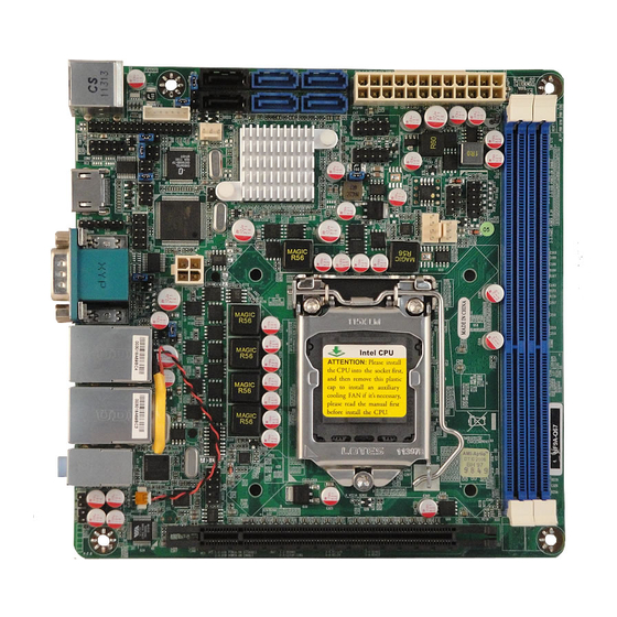
Page 8: Layout Diagram
Serial port header x1 RS422/RS485 header x1 CIR header x1 GPIO header x1 Speaker header x1 PWRLED header x1 Front panel header x1 Layout Diagram Rear IO Diagram RJ-45 LAN Ports Serial Port Line-IN USB Ports Line-OUT HDMI Port MIC-IN VGA Port PS/2 KB/MS USB Ports... - Page 9 Motherboard Internal Diagram SATAII Ports LVDS Inverter (SATA3/SATA4/ SATA5/SATA6) SATAIII Ports ATX Power connector (SATA1/SATA2) USB Ports over PS/2 KB/MS Port SYS1FAN Header USB Headers LVDS Header PWRLED Serial Port Header Header Speaker Header TX-RX COM SYS2FAN Header Header HDMI Port CPUFAN Header CIR Header Intel Q67 Chipset...
- Page 10 Motherboard Jumper Position JP10 JP11 COPEN JBAT LAN Chip LAN Chip Audio Chip...
- Page 11 Jumper Jumper Name Description JBAT CMOS RAM Clear Function Setting 3-pin Block JP10 KB/MS/USB Power On Function Setting 3 pin Block USB Port Power On Function Setting 3-pin Block USB1/2 Header Power On Function Setting 3-pin Block Inverter12V/5V Select 3-pin Block LVDS PVCC 5V/3.3V Select 3-pin Block COM2 Header RS232/485/422 Function Select...
- Page 12 Headers Header Name Description FP_AUDIO Front panel audio Header 9-pin block LVDS LVDS Header 35-pin Block INVERTER LVDS Inverter Connector 7-pin Block COM2 Serial Port Header 9-pin Block TX-RXCOM2 RS 422/485 port headers 4-pin block CIR Header 4-pin Block GPIO GPIO Header 10-pin Block USB1/USB2...
-
Page 13: Chapter 2 Hardware Installation
Chapter 2 Hardware Installation 2-1 Jumper Setting (1) Clear CMOS (3-pin): JBAT JBAT 1-2 Short: Normal 2-3 Short: Clear CMOS CMOS Clear Setting (2) KB/MS/USB Port 1/2 Power On Function Setting (3-pin): JP10 JP10 1-2 closed : KB/MS/USB Power-on Disabled (Default) JP10 2-3 closed: KB/MS/USB Power-on Power-on Enabled... - Page 14 (3) USB Port 3/4/5/6 Power On Function Setting(3-pin): JP5 1-2 closed : USB Port 3/4/5/6 Power-on Disabled (Default) 2-3 closed: USB Port 3/4/5/6 Power-on Enabled (4) USB 1/2 Header Power On Function Setting(3-pin): JP3 1-2 closed : USB1/2 Header Power-on Disabled (Default) 2-3 closed: USB1/2 Header Power-on Enabled...
- Page 15 (5) Inverter 5V/12V Select (3-pin):JP6 1-2 closed: Inverter 12V selected 2-3 closed: Inverter 5V select (6) LVDS PVCC 5V / 3.3V Function Setting (3-pin): JP7 1-2 closed: LVDS PVCC 5V 2-3 closed : LVDS PVCC 3.3V (7) COM2 Header RS232/422/485 Function Select (6-pin): JP9 1-2 closed: RS232 3-4 closed : RS485 5-6 closed : RS422...
- Page 16 (8) COM2 Pin9 Function Select (6-pin): JP11 JP11 1-2 closed: RS232 3-4 closed : +12V 5-6 closed : +5V (9)COPEN (2-pin): Case Open Message Display Function Select COPEN 1-2 Open: Normal 1-2 Short: Case Open Warnning Case Open Display Function Pin 1-2 shorted: Case open display function enabled.
-
Page 17: Connectors And Headers
Connectors and Headers 2-2-1 Connectors (1) Rear Panel Connectors RJ-45 LAN Ports Serial Port Line-IN USB Ports Line-OUT HDMI Port MIC-IN VGA Port PS/2 KB/MS USB Ports Port (2) Serial-ATAII Port connector: SATA3/SATA4/SATA5/SATA6 These connectors are high-speed SATAII ports that support 3 GB/s transfer rate. Pin No. -
Page 18: Headers
(3) Serial-ATAIII Port connector: SATA1/SATA2 These connectors are high-speed SATAIII ports that support 6 GB/s transfer rate. Pin No. Defnition 2-2-2 Headers (1) Line-Out, MIC-In Header (9-pin): FP_AUDIO This header connects to Front Panel Line-out, MIC-In connector with cable. FP_AUDIO Pin 1 Line-Out, MIC Headers... - Page 19 (2)LVDS Header (36 Pin): LVDS Pin NO. Pin Define Pin NO. Pin Define Pin 1 LVDSB_DATAN3 Pin 2 LVDSB_DATAP3 Pin 3 LVDSB_CLKBN Pin 4 LVDSB_DATABP Pin 5 LVDSB_DATAN2 Pin 6 LVDSB_DATAP2 Pin 7 LVDSB_DATAN1 Pin 8 LVDSB_DATAP1 Pin 9 LVDSB_DATAN0 Pin 10 LVDSB_DATAP0 Pin 11...
- Page 20 (3) LVDS Inverter Header: INVERTER Pin 1 and pin2: VCC of inverter Pin3, pin4 and pin6: GND Pin5: Backlight Pin7: Brightness Pin 1 (4) Serial Port Header (9-Pin): COM2 Pin6 Pin1 Pin1 Pin1 Pin5 Serial COM Port 9-pin Block...
- Page 21 (5) RS232/422/485 Header (4-Pin): TX-RXCOM2 Pin 1 TX-RXCOM2 Header (6) CIR Header (4-Pin): CIR Pin 1 CIR Header (7) GPIO Header (10-pin): GPIO GPIO Pin 1 GPIO_31 GPIO_30 GPIO_33 GPIO_32 GPIO_34 GPIO_35 GPIO_36 GPIO_37 GPIO Header...
- Page 22 (8) USB Port Headers (9-pin): USB1/USB2 Pin 1 USB Port Header (9) Front Panel Header (9-pin): JW-FP JW_FP Pin 1 System Case Connections (10) Power LED: The Power LED is light on while the system power is on. Connect the Power LED from the system case to this pin.
- Page 23 PIN1 PWRLED1 SPEAK PIN1 (12)FAN Speed Headers (3-pin): CPUFAN1, SYSFAN1/SYSFAN2 SYSFAN1 +12V Fan Power Fan Clock Control SYSFAN2 CPUFAN FAN Headers...
-
Page 24: Chapter 3 Introducing Bios
Chapter 3 Introducing BIOS The BIOS options in this manual are for reference only. Different Notice! configurations may lead to difference in BIOS screen and BIOS screens in manuals are usually the first BIOS version when the board is released and may be different from your purchased motherboard. Users are welcome to download the latest BIOS version form our official website. -
Page 25: Bios Menu Screen
BIOS Menu Screen The following diagram show a general BIOS menu screen: Menu Bar General Help Items Current Setting Value Menu Items Function Keys BIOS Menu Screen Function Key In the above BIOS Setup main menu of, you can see several options. We will explain these options step by step in the following pages of this chapter, but let us first see a short description of the function keys you may use here: Press←→... -
Page 26: Getting Help
Press <Enter> to select. Press <+>/<–> keys when you want to modify the BIOS parameters for the active option. [F1]: General help. [F2]: Previous value. [F3]: Optimized defaults. [F4]: Save & Reset. Press <Esc> to quit the BIOS Setup. Getting Help Main Menu The on-line description of the highlighted setup function is displayed at the top right corner the screen. -
Page 27: Main Menu
Main Menu Main menu screen includes some basic system information. Highlight the item and then use the <+> or <-> and numerical keyboard keys to select the value you want in each item. System Date Set the date. Please use [TAB] to switch between data elements. System Time Set the time. -
Page 28: Advanced Menu
3-7 Advanced Menu Launch External PxE OpROM/Launch LAN1 PXE OpROM/Launch LAN2 PXE OpROM Use this item to enable or disable boot option for legacy network devices. Launch Storage OpROM Use this item to enable or disable boot option for legacy mass storage devices with option ROM. - Page 29 PCI ROM Priority The optional settings: [Legacy ROM]; [EFI Compatible ROM]. Relaxed Ordering Use this item to enable or disable PCI express device relaxed ordering. Extended Tag If set as [Enabled] it will allow device to use 8-bit tag field as a requester. No Snoop Use this item to enable or disable PCI Express device No Snoop option.
- Page 30 Wake System with Dynamic Time Use this item to enable or disable system wake on alarm event. When set as [Enabled], system will wake on the current plus increased minute(s). CIR Wakeup Use this item to enable or disable CIR wakeup. PS2 KB/MS Wakeup Use this item to enable or disable PS2 KB/MS wakeup function.
- Page 31 The optional settings are: [Disabled]; [Energy Efficient]; [Custom]. ► SATA Configuration SATA Mode The optional settings are: [Disabled]; [IDE Mode]; [AHCI Mode]; [RAID Mode]. Serial-ATA Controller 0 The optional settings are: [Disabled]; [Enhanced]; [Compatible]. Serial-ATA Controller 1 The optional settings are: [Disabled]; [Enhanced]. ►...
- Page 32 Use this item to set maximum time the device will take before it properly reports itself to the host controller. ‘Auto’ uses default value: for a root port it is 100 ms, for a hub port the delay is taken from hub descriptor. The optional settings: [Auto]; [Manual].Select [Manual] you can set value for the following sub-item: Device Power-up delay in seconds, the delay range in from 1 to 40 seconds in one second increments.
- Page 33 Case Open Detect Use this item to detect case has already open or not, show message in POST. ► PC Health Status Press [Enter] to view hardware health status. ► AMT Configuration Press [Enter] to make settings for the following items: The optional settings are: [Enabled];...
- Page 34 PCH 1.8V Voltage Use this item to select a value for PCH 1.8V voltage. PCH 1.08V Voltage Use this item to select a value for PCH 1.08V voltage. DRAM Voltage select Use this item to select a value for DDR3 DRAM voltage. ►...
- Page 35 ► SmartFan Configuration CPUFAN / SYSFan1/ SYSFan2 Smart Mode When set as [Enabled], the following sub-items shall appear: CPUFAN N / SYSFan1/ SYSFan2 Full Speed Temp Use this item to set CPUFAN full speed temp. CPU FAN will run at full speed when above this temperature.
-
Page 36: Chipset Menu
3-8 Chipset Menu ► North Bridge LOW MMIO Align The optional settings are: [64M]; [1024M]. VT-d The optional settings are: [Enabled]; [Disabled]. Initiate Graphics Adapter Select which graphics controller to use as the primary boot device. The optional settings are: IGD; PEG/IGD. IGD Memory... - Page 37 Use this item to set IGD share memory size. IGD Multi-Monitor Use this item to enable or disable IGD multi-monitor by internal graphics device. PCI Express Port The optional settings are: [Auto];[Enabled]; [Disabled]. PEG Force Gen1 Use this item to enable or disable PCI Express port Force Gen1. Detect Mon-Compliance Device Use this item to enable or disable Non-Compliance PCI Express device in PEG.
- Page 38 High Precision Timer The optional settings are: [Enabled]; [Disabled]. ► PCI Express Ports Configuration Press [Enter] to further setting PCI Express ports configuration. ► USB Configuration Press [Enter] to further setting USB port configuration. ► ME subsystem ME Subsystem Use this item to enable or disable ME subsystem. ME Temporary Disable Use this item to enable or disable ME temporary disable help.
-
Page 39: Boot Menu
3-9 Boot Menu Setup Prompt Timeout Use this item to set number of seconds to wait for setup activation key. Bootup Numlock State Use this item to select keyboard numlock state.The optional settings are: [On]; [Off]. Quiet Boot The optional settings are: [Enabled]; [Disabled]. Gate A20 Active The optional settings are: [Upon Request];... -
Page 40: Security Menu
Use this item to set display mode for option ROM. The optional settings are: [Force BIOS]; [Keep Current]. Interrupt 19 Capture The optional settings are: [Enabled]; [Disabled]. 3-10 Security Menu Security menu allow users to change administrator password and user password settings. -
Page 41: Save & Exit Menu
3-11 Save & Exit Menu Save & Exit menu allows user to load optimal defaults, save or discard your changes to BIOS items.
Need help?
Do you have a question about the NF9A-Q67 and is the answer not in the manual?
Questions and answers