Table of Contents
Advertisement
Quick Links
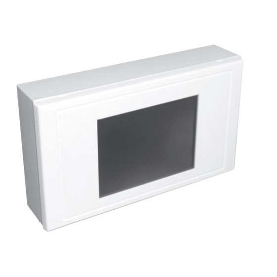
MRXBOX-VSC is a user control from the
Ecosmart range.
They have a 3.5in colour LCD touchscreen
display to provide improved user interface.
The unit can be surface or semi-recessed
mounted and is compatible with standard
2-gang recess back box.
MRXBOX-VSC– the unit is all plastic
construction and supplied with 10m of
pre-plugged connection cable and surface
mounting back box.
The units are SELV (12V d.c.) with the power
supplied from the fan unit via the pre-plugged
cable.
1.0 Installation
INSTALLED ENVIRONMENT
o
0-40
C and up to 90% RH non-condensing.
Caution: The unit must be installed away
from any direct source of heat (e.g. radiators)
and not in areas where it would be subjected
to steam or water spray.
The mounting surface must be free from
vibration.
The unit is supplied with back box suitable for
surface mounting. (see Figs. 1 - 5).
If semi-recess (final projection from wall is
7mm approx) is needed, a proprietary 2-gang
back box (25mm deep min.) may be used.
Always physically check the suitability of the
back box before fitting.
In some instances, the earthing point of the
back box may foul the unit and need to be
removed.
a) Fix one end of the 10m cable to the fan's
Ecosmart connection point and route the
cable to the mounting position.
b) Unclip the front bezel from the unit and
remove the 2 retaining screws, then remove
the working section from the back box. (see
Fig. 2).
MRXBOX VSC
Visual System User Control
Installation & Operating Instructions
c) Feed the cable through the knock-out hole
in the base of the back box and mark the
fixing point on the wall.
Drill appropriately sized holes at the fixing
points and insert the wall plugs.
Fix the back box on to the wall. (see Fig 3).
d) Plug the data cable into the socket.
(see Fig. 4).
e) Fix the unit back into the back box using
the screws supplied, then clip the bezel back
on the unit again noting which way is up.
(Top is printed on the inside face of the bezel
and and middle section). (see Fig. 5).
2.0 Data Cable Installation
A 4-core SELV data cable is used to connect
the control to the fan.
Do not run data cable in the same conduit
as the mains cables and ensure there is a
50mm separation between the data cable
and other cables.
For cable lengths in excess of 10m a
MRXBOX-JB will be required to provide
sufficient power. Keep the number of cable
joints to a minimum to ensure the best data
transmission efficiency between devices.
Due to the higher current consumed by the
MRXBOX-VSC, the max cable run between
the fan control and the MRXBOX-VSC must
be limited to 50m.
Nuaire Limited Western Industrial Estate Caerphilly United Kingdom CF83 1NA
T: 029 2085 8400 F: 029 2085 8444 E: info@nuaire.co.uk W: www.nuaire.co.uk
1
The EMC Directive
2004/108/EC
The Low Voltage
directive
2006/95/EC
Figure 1.
To fan connector
10m sensor connection
box terminal
wire (supplied).
marked NET
Clearance aperture for wire
should be approx 20mm dia
to allow passage of plug end.
Allow approx 120mm of wire
through for fitting to the
backplate.
Wire can be located behind
a wall panel or fixed to wall
surface.
Figure 2.
Remove the bezel and 2 screws to detach front
of unit from
back box.
Bezel
Front of unit.
Figure 3.
Feed cable
through hole
in back box.
Fix back box
to wall using
screws.
Figure 4.
Plug end mounted into the PCB socket inside
the front half of the unit. Note that the data
cable socket is
positioned at
the top corner
of the unit.
Figure 5.
Bezel
TOP
Front of unit
09. 03. 16. Leaflet Number 671703
Wall
Back box.
Back box.
Advertisement
Table of Contents

Related Manuals for NuAire MRXBOX-VSC

Summary of Contents for NuAire MRXBOX-VSC
- Page 1 (see Front of unit Fig. 2). Nuaire Limited Western Industrial Estate Caerphilly United Kingdom CF83 1NA T: 029 2085 8400 F: 029 2085 8444 E: info@nuaire.co.uk W: www.nuaire.co.uk 09. 03. 16. Leaflet Number 671703...
-
Page 2: The Home Screen
Installation and Operating Instructions MRXBOX-VSC User Control 3.0 Operating MRXBOX-VSC Using the Visual display screen will override any unit mounted controls. 3.1 The Home Screen Time Outside Temperature Status Indication Speed Indicator/ Filter Change Warning Adjustment Average Indoor Access to Function... - Page 3 Installation and Operating Instructions MRXBOX-VSC User Control 4.0 User Options Screen 4.3 Timed Boost Timed boost – Allows you to adjust the time the ventilation 4.1 Night Time Mode system boosts when the speed setting is changed via the home screen, this can be set between 1 and 60 minutes.
-
Page 4: Holiday Mode
Installation and Operating Instructions MRXBOX-VSC User Control 4.5 Rising Boost Rising Boost – Allows you to set the ventilation system so that the speed of the fan increases gradually, instead of going straight into full boost. 4.6 Holiday Mode Holiday Mode – Allows you to set the ventilation system to run at a minimum level while you are away. -
Page 5: Frost Protection
Commissioning – This should be carried out with reference to the ventilation units specific Installation and Maintenance instructions. By using the MRXBOX-VSC any controls on the front of the unit will become inoperable. However the requirement to meet building regulations will not change. -
Page 6: Maintenance
Installation and Operating Instructions MRXBOX-VSC User Control 5.4 Humidity (where fitted) 6.0 Maintenance Humidity – The unit monitors the humidity level of the whole Maintenance – After a pre-determined length of time the unit will property and boosts the unit if the level exceeds the set point. -
Page 7: Dimensions (Mm)
Please check the suitability of the fan unit before upgrading the existing user control to the MRXBOX-VSC controller. E = Screen To check if the fan is suitable for upgrade, please contact Nuaire width with detail of the fan code and the serial number printed on the... - Page 8 +44 (0)29 2085 8444 info@nuaire.co.uk www.nuaire.co.uk As part of our policy of continuous product development Nuaire reserves the right to alter specifications without prior notice. Telephone calls may be recorded for quality and training purposes. 09. 03. 16. Leaflet Number 671703...
Need help?
Do you have a question about the MRXBOX-VSC and is the answer not in the manual?
Questions and answers