Table of Contents
Advertisement
Advertisement
Table of Contents

Related Manuals for Asus ROG GR6


Summary of Contents for Asus ROG GR6
-
Page 1: User Guide
REPUBLIC OF GAMERS ROG GR6 User Guide... - Page 2 ASUS will only be responsible for or indemnify you for loss, damages or claims based in contract, tort or infringement under this Warranty Statement. This limit also applies to ASUS’ suppliers and its reseller. It is the maximum for which ASUS, its suppliers, and your reseller are collectively responsible.
-
Page 3: Table Of Contents
Using the Steam Big Picture Launcher .............22 Recovering your system.................23 Resetting your PC ...................23 Removing everything and reinstalling Windows® ......25 Turning off your ROG GR6 ................26 Putting your ROG GR6 to sleep ..............26 Entering the BIOS Setup ................26 Quickly enter the BIOS ..................27... - Page 4 Contents Upgrading your ROG GR6 Upgrading memory modules ..............30 Installing a 2.5-inch storage drive ..............35 Appendix Safety information ...................42 Setting up your system.................42 Care during use ....................43 Regulatory notices ...................44 ASUS contact information ................50...
-
Page 5: About This Manual
PC, organized through the following chapters: Chapter 1: Getting to know your ROG GR6 This chapter details the hardware components of your ROG GR6. Chapter 2: Using your ROG GR6 This chapter provides you with information on using your ROG GR6. -
Page 6: Package Contents
NOTE: * Actual product specifications and package contents may vary depending on your country or region. IMPORTANT! Bring the warranty card to the ASUS Service Center for replacement of the defective components if the device or its components fail or malfunction during normal and proper use within... -
Page 7: Getting To Know Your Rog Gr6
Getting to know your ROG GR6... -
Page 8: Features
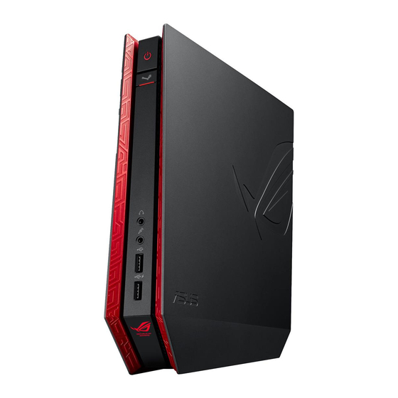
Features Front panel... -
Page 9: Power Button
Power button The power button allows you to turn the ROG GR6 on or off. Steam Big Picture Launcher The Steam Big Picture Launcher allows you to access Steam Big Picture mode from power off, sleep, hibernate, or Windows® operating system. -
Page 10: Bottom View
Bottom view Top view Air vents The air vents allow cool air to enter your ROG GR6 chassis and expel hot air out. IMPORTANT! For optimum heat dissipation and air ventilation, ensure that the air vents are free from obstructions. -
Page 11: Rear Panel
Rear panel HDD/Drive LED indicator This indicator lights up when your ROG GR6 is accessing the internal storage drives. Audio Input Jack This 1/8-inch stereo input jack can be used to connect a stereo audio source to the ROG GR6. This feature is used mainly to add audio to multimedia applications. -
Page 12: Microphone Jack
Digital audio out port (S/PDIF optical) The Sony/Philips Digital Interface (S/PDIF) optical out port allows you to transfer digital audio from your ROG GR6 into an amplifier or your TV. HDMI port This port is for the HDMI (High-Definition Multimedia Interface) connector and is HDCP compliant for HD DVD, Blu-ray, and other protected content playback. - Page 13 Do not cover the adapter and keep it away from your body. Cover lock latch + Kensington security slot The cover lock latch fastens the side cover on your ROG GR6. The Kensington security slot allows you to secure your ROG GR6 using Kensington® security products.
-
Page 15: Using Your Rog Gr6
Using your ROG GR6... -
Page 16: Getting Started
Getting started Positioning your ROG GR6 The ROG GR6 can be positioned standing up or lying down. When positioning your ROG GR6, ensure that the rubber studs or the rubber feet are in contact with the flat and stable surface of your table or desk. -
Page 17: Connecting The Ac Power Adapter
Connecting the AC power adapter To connect the AC power adapter to your ROG GR6: A. Connect the AC power cord to the AC/DC adapter. Plug the AC power cord into a 100V~240V power source. Connect the DC power connector into your ROG GR6’s power (DC) input port. - Page 18 IMPORTANT! • We strongly recommend that you use only the AC power adapter and cable that came with your ROG GR6. • Use a grounded wall socket while using your ROG GR6. • The socket outlet must be easily accessible and near your ROG GR6. • To disconnect your ROG GR6 from its main power supply, unplug your ROG GR6 from the power socket.
-
Page 19: Connecting A Display Panel
Connecting a display panel You can connect a display panel or projector to your ROG GR6 that has the following connectors: • HDMI connector • DisplayPort connector To connect a display panel to your ROG GR6: Connect a display cable either to the HDMI or DisplayPort port. -
Page 20: Connecting The Keyboard Or Mouse
Connecting the keyboard or mouse You can connect generally any USB keyboard and mouse to your ROG GR6. You can also connect a USB dongle for a wireless keyboard and mouse set. To connect a keyboard and mouse to your ROG GR6: Connect the USB cable from your keyboard and mouse to any of the USB 2.0/3.0 ports of your ROG GR6. -
Page 21: Turning On Your Rog Gr6
Turning on your ROG GR6 Press the power button to turn on your ROG GR6. -
Page 22: Using The Steam Big Picture Launcher
Using the Steam Big Picture Launcher The ROG GR6 allows you to access Steam Big Picture mode from power off, sleep, hibernate, or Windows® operating system. Access Steam Big Picture Mode In the following states, press the Steam Big Picture Launcher to access Steam Big Picture mode: •... -
Page 23: Recovering Your System
IMPORTANT! This section only applies for models with the bundled operating system installed in your ROG GR6. Resetting your PC The Reset your PC option restores your ROG GR6 to its factory default settings. IMPORTANT! Back up all your data before using this option. -
Page 24: Creating A Usb Recovery Drive
Creating a USB recovery drive You can create a USB recovery drive and use this to recover your PC’s settings. WARNING! All files on your USB storage device will be permanently deleted during the process. Before you proceed, ensure that you back up all your important data. -
Page 25: Removing Everything And Reinstalling Windows
IMPORTANT! This section only applies for models with the bundled operating system installed in your ROG GR6. Restoring your ROG GR6 to its original factory settings can be done using the Remove everything and reinstall option in PC Settings. Refer to the steps below to use this option. -
Page 26: Turning Off Your Rog Gr6
Turning off your ROG GR6 Click Shutdown in Windows® operating system or press the Power button to shut down your ROG GR6. If your ROG GR6 is unresponsive, press and hold the power button for at least four (4) seconds until your ROG GR6 turns off. -
Page 27: Quickly Enter The Bios
GR6 back on, and then press <F2> or <Del> during POST. • When your ROG GR6 is off, press the power button to turn on your ROG GR6. Press <F2> or <Del> during POST. NOTE: POST (Power-On Self Test) is a series of software controlled diagnostic tests that run when you turn on your PC. -
Page 29: Upgrading Your Rog Gr6
Upgrading your ROG GR6... -
Page 30: Upgrading Memory Modules
Turn off your ROG GR6. Disconnect all cables and peripherals. Place the ROG GR6 on its side on a stable and flat surface. Move down the latch at the rear panel to unlock the side cover. NOTE: Before you remove the side cover, ensure that the UNLOCK... - Page 31 Slide the side cover towards the rear to detach it from the chassis and then gently lift to remove it from the chassis. Pry open the SO-DIMM slot cover.
- Page 32 Remove the memory modules. To remove a memory module: A. Press the retaining clips on each side to release the memory module. B. Carefully remove the memory module. C. Repeat steps A and B to remove the other memory module. NOTE: • Use the same model and speed when replacing memory modules.
- Page 33 Get the replacement memory modules. Install the new memory modules into the slot. IMPORTANT! Always install on the lower slot first when installing one or two modules. To install a new memory module: Align and insert the memory module into the slot (A) and then press it down (B) until it is securely seated in place.
- Page 34 11. Replace the side cover and then slide it towards the front of ROG GR6 to re-attach. 12. Press the latch upward to securely fasten the side cover to the chassis.
-
Page 35: Installing A 2.5-Inch Storage Drive
Turn off your ROG GR6. Disconnect all cables and peripherals. Place the ROG GR6 on its side on a stable and flat surface. Press down the latch at the rear panel to unlock the side cover. NOTE: Before you remove the side cover, ensure that the UNLOCK... - Page 36 Slide the side cover towards the rear to detach it from the chassis and then gently lift to remove it from the chassis. Remove the four screws that secure the 2.5-inch HDD/SSD extension bay. Using the flap, pull the extension bay to remove it from the chassis.
- Page 37 Prepare the 2.5-inch HDD/SSD and the bundled set of four screws. Turn the extension bay upside down and place the 2.5-inch HDD/SSD into the extension bay as shown. Ensure that screw holes on the 2.5-inch HDD/SSD match the screw holes on the extension bay.
- Page 38 11. Carefully place the 2.5-inch HDD/SSD and extension bay assembly into the drive bay and then slide it towards the SATA connector. 2.5-inch HDD/SSD and extension bay assembly HDD/SSD SATA connector Drive bay SATA connector 12. Secure the 2.5-inch extension bay with four screws.
- Page 39 13. Replace the side cover and then slide it towards the front of ROG GR6 to re-attach. 14. Move the latch upward to securely fasten the side cover to the chassis.
-
Page 41: Appendix
Appendix... -
Page 42: Safety Information
Safety information Your ROG GR6 is designed and tested to meet the latest standards of safety for information technology equipment. However, to ensure your safety, it is important that you read the following safety instructions. Setting up your system • Read and follow all instructions in the documentation before you operate your system. -
Page 43: Care During Use
The warranty does not apply to the products that have been disassembled by users DO NOT throw the ROG GR6 in municipal waste. This product has been designed to enable proper reuse of parts and recycling. This symbol of the crossed out wheeled bin indicates that the product (electrical, electronic equipment, and mercury-containing button cell battery) should not be placed in municipal waste. -
Page 44: Regulatory Notices
REACH Complying with the REACH (Registration, Evaluation, Authorization, and Restriction of Chemicals) regulatory framework, we publish the chemical substances in our products at ASUS REACH website at http://csr.asus.com/english/REACH.htm ASUS Recycling/Takeback Services ASUS recycling and takeback programs come from our commitment to the highest standards for protecting our environment. -
Page 45: Rf Exposure Warning
radio or television reception, which can be determined by turning the equipment off and on, the user is encouraged to try to correct the interference by one or more of the following measures: • Reorient or relocate the receiving antenna. • Increase the separation between the equipment and receiver. • Connect the equipment to an outlet on a circuit different from that to which the receiver is connected. • Consult the dealer or an experienced radio/TV technician for help. -
Page 46: France Restricted Wireless Frequency Bands
France Restricted Wireless Frequency Bands Some areas of France have a restricted frequency band. The worst case maximum authorized power indoors are: • 10mW for the entire 2.4 GHz band (2400 MHz–2483.5 MHz) • 100mW for frequencies between 2446.5 MHz and 2483.5 MHz NOTE: Channels 10 through 13 inclusive operate in the band 2446.6 MHz to 2483.5 MHz. There are few possibilities for outdoor use: On private property or on the private property of public persons, use is subject to a preliminary authorization procedure by the Ministry of Defense, with maximum... -
Page 47: Canadian Department Of Communications Statement
This requirement is likely to change over time, allowing you to use your wireless LAN card in more areas within France. Please check with ART for the latest information (www.art-telecom.fr) NOTE: Your WLAN Card transmits less than 100mW, but more than 10mW. -
Page 48: Ce Mark Warning
CE Mark Warning CE marking for devices without wireless LAN/Bluetooth The shipped version of this device complies with the requirements of the EEC directives 2004/108/EC “Electromagnetic compatibility” and 2006/95/EC “Low voltage directive”. CE marking for devices with wireless LAN/ Bluetooth This equipment complies with the requirements of Directive 1999/5/ EC of the European Parliament and Commission from 9 March, 1999 governing Radio and Telecommunications Equipment and mutual... -
Page 49: Energy Star Complied Product
Department of Energy helping us all save money and protect the environment through energy efficient products and practices. All ASUS products with the ENERGY STAR logo comply with the ENERGY STAR standard, and the power management feature is enabled by default. The monitor and computer are automatically set to sleep after 10 and 30 minutes of user inactivity. -
Page 50: Asus Contact Information
+1-510-739-3777 +1-510-608-4555 Web site http://www.asus.com/us/ Technical Support Support fax +1-812-284-0883 Telephone +1-812-282-2787 Online support http://qr.asus.com/techserv ASUS COMPUTER GmbH (Germany and Austria) Address Harkort Str. 21-23, D-40880 Ratingen, Germany +49-2102-959911 Web site http://www.asus.com/de Online contact http://eu-rma.asus.com/sales Technical Support Telephone +49-1805-010923* Support Fax... -
Page 51: Eu Declaration Of Conformity
We, the undersigned, Manufacturer: ASUSTeK COMPUTER INC. Address: 4F, No. 150, LI-TE Rd., PEITOU, TAIPEI 112, TAIWAN Authorized representative in Europe: ASUS COMPUTER GmbH Address, City: HARKORT STR. 21-23, 40880 RATINGEN Country: GERMANY declare the following apparatus: Product name :... -
Page 52: Declaration Of Conformity
DECLARATION OF CONFORMITY Per FCC Part 2 Section 2. 1077(a) Asus Computer International Responsible Party Name: , CA 94539. Address: 800 Corporate Way, Fremont Phone/Fax No: (510)739-3777/(510)608-4555 hereby declares that the product Product Name : Desktop PC Model Number :GR8,GR6...
Need help?
Do you have a question about the ROG GR6 and is the answer not in the manual?
Questions and answers