Table of Contents
Advertisement
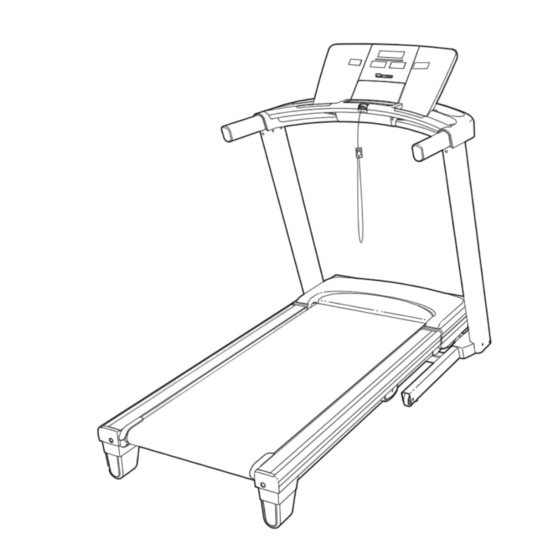
Model No. NTL09107.0
Serial No.
Write the serial number in the space
above for reference.
Serial Number
Decal
QUESTIONS?
As a manufacturer, we are com-
mitted to providing complete cus-
tomer satisfaction. If you have
questions, or if parts are missing,
PLEASE DO NOT CONTACT
THE STORE; please contact
Customer Care.
IMPORTANT: You must note the
product model number and
serial number (see the drawing
above) before contacting us:
CALL TOLL-FREE:
1-888-825-2588
Mon.–Fri. 6 a.m.–6 p.m. MST
Sat. 8 a.m.–4 p.m. MST
ON THE WEB:
www.nordictrackservice.com
CAUTION
Read all precautions and instruc-
tions in this manual before using
this equipment. Save this manual
for future reference.
With Universal Dock for iPod
®
USER'S MANUAL
Visit our website at
www.nordictrack.com
new products, prizes,
fitness tips, and much more!
Advertisement
Table of Contents

Related Manuals for NordicTrack A2550 NTL09107.0


Summary of Contents for NordicTrack A2550 NTL09107.0
- Page 1 ON THE WEB: www.nordictrackservice.com CAUTION Read all precautions and instruc- tions in this manual before using this equipment. Save this manual for future reference. ® USER'S MANUAL Visit our website at www.nordictrack.com new products, prizes, fitness tips, and much more!
-
Page 2: Table Of Contents
HOW TO FOLD AND MOVE THE TREADMILL ........ -
Page 3: Important Precautions
To reduce the risk of serious injury, read all important precautions and in- structions in this manual and all warnings on your treadmill before using your treadmill. ICON as- sumes no responsibility for personal injury or property damage sustained by or through the use of this product. - Page 4 (See the drawing on page 5 for the location of the circuit breaker.) 21. Do not attempt to raise, lower, or move the treadmill until it is properly assembled.
-
Page 5: Before You Begin
BEFORE YOU BEGIN Thank you for selecting the revolutionary NordicTrack A2550 treadmill with Universal Dock for iPod A2550 treadmill offers a selection of features designed to make your workouts at home more enjoyable and effective. When you’re not exercising, the unique A2550 treadmill can be folded up, requiring less than half the floor space of other treadmills. -
Page 6: Assembly
This is a normal condition and does not affect treadmill performance. If there is lubricant on top of the walking belt, simply wipe off the lubricant with a soft cloth and a mild, non-abrasive cleaner. - Page 7 1. Make sure that the power cord is unplugged. With the help of a second person, carefully tip the treadmill onto its left side. Partially fold the Frame (56) so that the treadmill is more stable; do not fully fold the Frame yet.
- Page 8 Bolts yet. 5. With the help of a second person, carefully tip the treadmill onto its right side. Partially fold the Frame (56) so that the treadmill is more stable; do not fully fold the Frame yet.
- Page 9 7. Remove the plastic ties from the handrail assem- bly. If necessary, press the Cage Nuts (33) into place. With the help of a second person, hold the handrail assembly near the Right Upright (78) and the Left Upright (74). Connect the Upright Wire (38) to the console wire.
- Page 10 THE TREADMILL FOR USE on page 24). 13. Make sure that all parts are properly tightened before you use the treadmill. If there are sheets of clear plastic on the treadmill decals, remove the plastic. To protect the floor or carpet, place a mat under the tread- mill.
- Page 11 If you purchase the optional chest pulse sensor (see page 22), follow the steps below to install the re- ceiver included with the chest pulse sensor. 1. Make sure that the power cord is unplugged. Remove the indicated #8 x 3/4" Screw (12) and the Access Door (87) from the Console Back (91).
-
Page 12: Operation And Adjustment
(see drawing 1 at the right). To purchase a surge suppressor, see your local NordicTrack dealer or call the telephone number on the front cover of this manual and order part number 146148, or see your local electronics store. -
Page 13: Console Diagram
Each workout automatically controls the speed and incline of the treadmill as it guides you through an effective workout. You can create your own custom workouts. You can even take a fitness test that mea- sures your fitness age. -
Page 14: How To Turn On The Power
“reset” position. IMPORTANT: The console features a display demo mode, designed to be used if the treadmill is dis- played in a store. If the displays light as soon as you plug in the power cord and switch the reset/off circuit breaker to the reset position, the demo mode is turned on. - Page 15 4. Change the incline of the treadmill as desired. To change the incline of the treadmill, press the Incline increase and decrease buttons or one of the numbered 1 Step Incline buttons. Each time you press one of the buttons, the incline will gradu- ally change until it reaches the selected incline set- ting.
- Page 16 Step onto the foot rails, press the Stop button, and adjust the incline of the treadmill to the lowest setting. The incline must be at the lowest setting when you fold the treadmill to the storage posi- tion, or you may damage the treadmill.
-
Page 17: Preset Workout
3. Press the Start button to start the workout. A moment after you press the button, the treadmill will automatically adjust to the first speed and in- cline settings of the workout. Hold the handrails and begin walking. - Page 18 To restart the workout, press the Start button or the Speed increase button. The walking belt will begin to move at 1 mph. When the next segment of the workout begins, the treadmill will automatically adjust to the speed and incline settings for the next segment.
- Page 19 4. Press the Start Fitness Test button to start the workout. A moment after you press the button, the treadmill will automatically adjust to the first speed and in- cline settings of the workout. Begin walking on the treadmill. Note: For the most accurate results, do not hold the handrails during the fitness test work- out.
- Page 20 The workout is de- signed to last for nine minutes. When the workout ends, the walk- ing belt will slow to a stop and your fitness age will appear in the Fitness Age Calculator dis- play. 5. Monitor your progress with the displays. See step 5 on page 15.
-
Page 21: How To Use Ifit Card
3. Press the Start button to start the workout. A moment after you press the Start button, the treadmill will automatically adjust to the first speed and incline settings of the workout. Hold the handrails and begin walking. The voice of a per- sonal trainer will guide you through the workout. - Page 22 The console features an information mode that keeps track of the total distance that the walking belt has moved and the total number of hours that the treadmill has been used. The information mode also allows you to select a measurement system of miles or kilome- ters, and to turn on and off the display demo mode.
-
Page 23: Fold For Storage
1. Hold a handrail and the frame and place one foot against one of the wheels. 2. Tilt the treadmill back until it rolls freely on the wheels. Carefully move the treadmill to the desired location. Never move the treadmill without tipping it back. To reduce the risk of injury, use extreme caution while moving the treadmill. -
Page 24: How To Lower Treadmill For Use
HOW TO LOWER THE TREADMILL FOR USE 1. Hold the upper end of the treadmill with your right hand. Pull the latch knob to the left and hold it. It may be neces- sary to push the frame forward as you pull the knob to the left. -
Page 25: Troubleshooting
PROBLEM: The console displays remain lit when you remove the key from the console SOLUTION: a. The console features a display demo mode, designed to be used if the treadmill is displayed in a store. If the displays remain lit when you remove the key, the demo mode is turned on. To turn off the demo mode, hold down the Stop button for a few seconds. - Page 26 SOLUTION: a. With the key in the console, press one of the Incline buttons. While the incline is changing, re- move the key. After a few seconds, re-insert the key. The treadmill will automatically rise to the maximum incline level and then return to the minimum level. This will recalibrate the incline system.
- Page 27 Be careful to keep the walk- ing belt centered. Then, plug in the power cord, in- sert the key, and carefully walk on the treadmill for a few minutes. Repeat until the walking belt is properly tightened.
-
Page 28: Exercise Guidelines
EXERCISE GUIDELINES WARNING: Before beginning this or any exercise program, consult your physi- cian. This is especially important for persons over the age of 35 or persons with pre-exist- ing health problems. The pulse sensor is not a medical device. Various factors may affect the accuracy of heart rate readings. -
Page 29: Suggested Stretches
SUGGESTED STRETCHES The correct form for several basic stretches is shown at the right. Move slowly as you stretch—never bounce. 1. Toe Touch Stretch Stand with your knees bent slightly and slowly bend forward from your hips. Allow your back and shoulders to relax as you reach down toward your toes as far as possible. -
Page 30: Part List
PART LIST—Model No. NTL09107.0 To locate the parts listed below, see the EXPLODED DRAWING near the end of this manual. Key No. Qty. Description #8 x 1/2" Screw #8 x 1" Tek Screw Hex Key 3/8" x 2" Bolt 1/4" x 1 1/4" Bolt 3/8"... - Page 31 Key No. Qty. Description Pulse Bar Ground Wire Latch Endcap iFIT Card Kit Lift Motor Spacer #8 x 2" Screw Right Handrail Trim Rear Roller Ground Wire iFIT Universal iPod Connector Foot Rail Insert Cushion Stop Screw Key No. Qty. Description Rear Roller Bracket Plate 5/32"...
-
Page 32: Exploded Drawing
EXPLODED DRAWING A—Model No. NTL09107.0 R0308A... - Page 33 EXPLODED DRAWING B—Model No. NTL09107.0 R0308A...
- Page 34 EXPLODED DRAWING C—Model No. NTL09107.0 R0308A...
- Page 35 EXPLODED DRAWING D—Model No. NTL09107.0 R0308A...
-
Page 36: Ordering Replacement Parts
ORDERING REPLACEMENT PARTS To order replacement parts, please see the front cover of this manual. To help us assist you, be prepared to pro- vide the following information when contacting us: • the model number and serial number of the product (see the front cover of this manual) •...
Need help?
Do you have a question about the A2550 NTL09107.0 and is the answer not in the manual?
Questions and answers