Table of Contents
Advertisement
Quick Links
Advertisement
Table of Contents

Related Manuals for ESAB CUTMASTER A60


Summary of Contents for ESAB CUTMASTER A60
- Page 1 CUTMASTER ® AUTOMATED PLASMA CUTTING SYSTEM Operating Manual Art # A-12877 OUTPUT MAX OUTPUT INPUT POWER INPUT POWER VOLTAGE VOLTAGE VOLTAGE VOLTAGE 400V 460V 600V 208-230V PHASE PHASE AMPS esab.eu Revision: AA Issue Date: August 30, 2015 Manual No.: 0-5428...
- Page 2 WE APPRECIATE YOUR BUSINESS! Congratulations on your new ESAB product. We are proud to have you as our customer and will strive to provide you with the best service and reliability in the industry. This prod- uct is backed by our extensive warranty and world-wide service network. To locate your nearest distributor or service agency, visit us on the web at www.esab.eu.
- Page 3 2800 Airport Rd. Denton, TX 76208 (940) 566-2000 www.esab.eu Copyright 2015 by ESAB All rights reserved. Reproduction of this work, in whole or in part, without written permission of the publisher is prohibited. The publisher does not assume and hereby disclaims any liability to any party for any loss or damage caused by any error or omission in this Manual, whether such error results from negligence, accident, or any other cause.
- Page 4 Be sure this information reaches the operator. You can get extra copies through your supplier. CAUTION These INSTRUCTIONS are for experienced operators. If you are not fully familiar with the principles of operation and safe practices for arc welding and cutting equip- ment, we urge you to read our booklet, “Precautions and Safe Practices for Arc Welding, Cutting, and Gouging,”...
-
Page 6: Table Of Contents
TABLE OF CONTENTS SECTION 1: SAFETY ..................1-1 Safety Precautions ..................1-1 SECTION 2 SYSTEM: INTRODUCTION ..............2-1 2.01 How To Use This Manual ................2-1 2.02 Equipment Identification ................. 2-1 2.03 Receipt Of Equipment ..................2-1 2.04 Power Supply Specifications ................2-2 2.05 Input Wiring Specifications ................ - Page 7 TABLE OF CONTENTS PATENT INFORMATION ................. 4T-46 SECTION 5 SYSTEM: SERVICE ................5-1 5.01 General Maintenance ..................5-1 5.02 Maintenance Schedule ..................5-2 5.03 Common Faults ....................5-2 5.04 Fault Indicator ....................5-2 5.05 Basic Troubleshooting Guide ................5-4 5.06 Power Supply Basic Parts Replacement ............
- Page 8 This Page Intentionally Blank.
-
Page 9: Section 1: Safety
SECTION 1: SAFETY Safety Precautions Users of ESAB welding and plasma cutting equipment have the ultimate responsibility for ensuring that anyone who works on or near the equipment observes all the relevant safety precautions. Safety precautions must meet the requirements that apply to this type of welding or plasma cutting equipment. - Page 10 CUTMASTER A60 Arc welding and cutting can be injurious to yourself and others. Take WARNING precautions when welding and cutting. Ask for your employer's safety practices which should be based on manufacturers' hazard data. ELECTRIC SHOCK - Can kill. - Install and earth (ground) the welding or plasma cutting unit in accordance with applicable standards.
-
Page 11: Section 2 System: Introduction
Include the Owner’s Manual number and equipment identifica- tion numbers. Electronic copies of this manual can also be downloaded at no charge in Acrobat PDF format by going to the ESAB web site listed below http://www.esab.eu 0-5428... -
Page 12: Power Supply Specifications
20 - 80 Amps, Continuously Adjustable Power Supply Gas Filtering Particulates to 5 Microns Ability Cutmaster A60 Power Supply Duty Cycle * Duty Cycle Ratings @ 40° C (104° F) Ambient Temperature Operating Range 0° - 50° C IEC Rating... -
Page 13: Input Wiring Specifications
CUTMASTER A60 2.05 Input Wiring Specifications Cutmaster A60 Power Supply Input Cable Wiring Requirements Input voltage Freq Power Input Suggested Sizes Flexible Cord Volts I max I eff Fuse (amps) (Min. AWG) 1 Phase 50/60 50/60 11.8 3 Phase 50/60 11.8 Line Voltages with Suggested Circuit Protection and Wire Sizes... -
Page 14: Power Supply Features
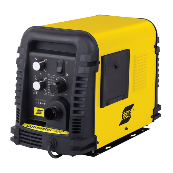
CUTMASTER A60 2.06 Power Supply Features Control Panel Art # A-08306 Torch Leads Receptacle Mounting Rails Work Cable and Clamp Automation Interface Cable Port Input Power Selection Filter Assembly Gas Inlet Port Input Power Cord Art # A-08318 INTRODUCTION 0-5428... -
Page 15: Section 2 Torch: Introduction
CUTMASTER A60 SECTION 2 TORCH: 2T.03 Specifications INTRODUCTION A. Torch Configurations 1. Automation Torch, Model 2T.01 Scope of Manual The standard automation torch has a position- ing tube with rack & pinch block assembly and a This manual contains descriptions, operating instructions solenoid valve. -
Page 16: 04 Options And Accessories
CUTMASTER A60 C. Torch Parts H. Direct Contact Hazard Starter Cartridge, Electrode, Tip, Shield Cup For standoff tip the recommended standoff is 3/16 inches / 4.7 mm. D. Parts - In - Place (PIP) 2T.04 Options And Accessories Torch Head has built - in switch For options and accessories, see Section 6. - Page 17 CUTMASTER A60 of heat to a small area. The stiff, constricted plasma nected to the workpiece via the work cable and to arc is shown in Zone C. Direct current (DC) straight the torch through a pilot wire. polarity is used for plasma cutting, as shown in the illustration.
- Page 18 CUTMASTER A60 This Page Intentionally Blank INTRODUCTION 0-5428 2T-4...
-
Page 19: Section 3 System: Installation
CUTMASTER A60 SECTION 3 SYSTEM: 2. Place the unit in the desired position and mark where the four keyway holes in the mounting rails INSTALLATION touch. 3.01 Unpacking 3. Remove the unit and using these markings, prepare holes for mounting hardware. -
Page 20: Primary Input Power Connections
CUTMASTER A60 3.05 Primary Input Power Connections 2. Carefully pull the Cover up and away from the unit. CAUTION Check your power source for correct B. Cover Installation voltage before plugging in or connecting 1. Reverse previous procedures for cover installa- the unit. - Page 21 CUTMASTER A60 8. Reinstall the Power Supply cover. See "B. NOTE! Cover Installation". There is only one jumper setting that changes between the single and three 9. Connect the opposite end of individual wires to phase settings. To change from single a customer supplied plug or main disconnect.
-
Page 22: Gas Connections
CUTMASTER A60 3. Connect the air line to the Filter. The illustration 9. Connect the opposite end of individual wires to shows typical fittings as an example. a customer supplied plug or main disconnect. NOTE! 10. Connect the input power cable (or close the main For a secure seal, apply thread seal- disconnect switch) to supply power. - Page 23 CUTMASTER A60 Regulator/Filter NOTE! Assembly Pressure should be set at 100 psi 2-Stage Filter Inlet Port (IN) (6.9 bar) at the high pressure cylin- Regulator Input der regulator. Outlet Port Supply hose must be at least 1/4 (OUT) inch (6 mm) I.D.
- Page 24 CUTMASTER A60 This Page Intentionally Blank INSTALLATION 0-5428...
-
Page 25: Section 3 Torch: Installation
If necessary, connect the torch to the Power Supply. turn ON the air. Do not start an arc! Connect only the ESAB model SL100SV / Automation, Any oil or moisture in the air will be visible on the lens. SL100 / Mechanical or SL60 / Manual Torch to this power supply. -
Page 26: 03 Automation Interface Pcb With Ohmic Sense
CUTMASTER A60 3T.03 Automation Interface PCB with Ohmic Sense The new Automation Interface PCB with Ohmic Sense adds additional selectable divided voltage ratios and selectable polarity of the divided signal. The board also has Ohmic sensing for use with the iHC XT via ei- ther the exposed torch tip or via a separate connection to the torch tip. -
Page 27: 04 Setting Up Automation Or Machine Torch
CUTMASTER A60 DIVIDE RATIO SET BY DIP SW DIV1 DIV1-1 ON = 16.7:1 for SC11 DIV1-4 ON = 40:1 for Inova DIV1-2 ON = 20:1 for ESAB DIV1-5 ON = 50:1 for IHT: DIV1-3 ON = 30:1 SC3000 & 3100; Hypertherm ®... - Page 28 CUTMASTER A60 Pinch Block Assembly Square Workpiece A-02585 Automated and Machine Torch Set - Up 3. The proper torch parts (shield cup, tip, start car- tridge, and electrode) must be installed for the type of operation. Refer to Section 4T.08, Torch Parts Selection for details.
-
Page 29: Section 4 System: Operation
CUTMASTER A60 SECTION 4 SYSTEM: OPERATION 4.01 Front Panel Controls / Features See Illustration for numbering Identification 1. Output Current Control Sets the desired output current. Output settings up to 60 Amps may be used for drag cutting (with the torch tip contacting the workpiece) or higher for standoff cutting. -
Page 30: Preparations For Operation
Check that the torch is properly connected. Only Set Operating Pressure ESAB model SL60 / Manual, SL100 / Mechanical or SL100 / SV Automation Torches may be connected 1. Place the Power Supply Function Control knob to this Power Supply. - Page 31 Art# A-07946 STANDOFF Typical Cutting Speeds Cutmaster A60 Gas Pressure Settings Cutting speeds vary according to torch output am- SL100 perage, the type of material being cut, and operator SL60 (Mechanized Torch) skill.
- Page 32 CUTMASTER A60 This Page Intentionally Blank OPERATION 0-5428...
-
Page 33: Section 4 Torch: Operation
CUTMASTER A60 SECTION 4 TORCH: For optimum smooth surface quality, the travel speed should be adjusted so that only the leading edge OPERATION of the arc column produces the cut. If the travel speed is too slow, a rough cut will be produced as the arc moves from side to side in search of metal 4T.01 Machine and Automated Torch... -
Page 34: 03 Machine And Hand Torch Parts Selection
CUTMASTER A60 4T.03 Machine and Hand Torch Parts WARNING Selection Disconnect primary power at the source before assembling or disassembling Depending on the type of operation to be done deter- torch parts, or torch and leads assem- mines the torch parts to be used. -
Page 35: 04 Cut Quality
CUTMASTER A60 Shown) Top - Edge Rounding Rounding on the top edge of a cut due to wearing 3. Install the replacement Electrode by pushing it from the initial contact of the plasma arc on the straight into the torch head until it clicks. -
Page 36: 06 Hand Torch Operation
CUTMASTER A60 4T.06 Hand Torch Operation Edge Starting For edge starts, hold the torch perpendicular to the workpiece with the front of the tip near (not touching) Standoff Cutting With Hand Torch the edge of the workpiece at the point where the cut NOTE! is to start. - Page 37 CUTMASTER A60 Trigger Shield Cup Standoff Guide Trigger Release Torch Tip A-02986 Workpiece Art # A-04034 5. Bring the torch within transfer distance to the Shield Cup With Straight Edge work. The main arc will transfer to the work, and The drag shield cup can be used with a non conduc- the pilot arc will shut OFF.
- Page 38 CUTMASTER A60 5. Hold the torch away from your body. Piercing With Hand Torch 1. The torch can be comfortably held in one hand 6. Slide the trigger release toward the back of the torch handle while simultaneously squeezing the or steadied with two hands.
-
Page 39: 07 Gouging
CUTMASTER A60 Cutting speed depends on material, thickness, and the Current Setting operator’s ability to accurately follow the desired cut line. Current settings depend on torch travel speed, The following factors may have an impact on system mode of operation (hand or machine torch), and the performance: amount of material to be removed. -
Page 40: 08 Recommended Cutting Speeds For Machine And Automated Torches With Exposed Tip
CUTMASTER A60 4T.08 Recommended Cutting Speeds for Machine and Automated Torches With Exposed Tip Mild Steel Air Plasma / Air Shield Starter Cartridge Standard Shield Cup Deflector Heavy Duty Starter Electrode Maximum Life Shield Cup Cartridge 9-8218 9-8213 9-8243 9-8208... - Page 41 CUTMASTER A60 Torch Initial Kerf Width Material Gas Pressure Arc Voltage Working Travel Speed Piercing Pierce Delay @ Rec. Thickness (Air) Height Height Speed (mm) (torch lead Volts (mm) (mm/min) (mm) (sec) (mm) length) 3990 2920 1810 1470 4.8 (7.6m) 1345 5.2 (15.2m)
- Page 42 CUTMASTER A60 Stainless Steel Air Plasma / Air Shield Starter Cartridge Standard Shield Cup Deflector Heavy Duty Starter Electrode Maximum Life Shield Cup Cartridge 9-8218 9-8213 9-8243 9-8208 9-8232 9-8237 9-8277 Torch Initial Kerf Width Material Gas Pressure Arc Voltage...
- Page 43 CUTMASTER A60 Torch Initial Kerf Width Material Gas Pressure Arc Voltage Working Travel Speed Piercing Pierce Delay @ Rec. Thickness (Air) Height Height Speed (mm) (torch lead Volts (mm) (mm/min) (mm) (sec) (mm) length) 1670 1140 5.2 (7.6m) 5.5 (15.2m) Edge Start BOLD TYPE indicates maximum piercing parameters.
- Page 44 CUTMASTER A60 Aluminum Air Plasma / Air Shield Starter Cartridge Standard Shield Cup Deflector Heavy Duty Starter Electrode Maximum Life Shield Cup Cartridge 9-8218 9-8213 9-8243 9-8208 9-8232 9-8237 9-8277 Torch Initial Kerf Width Material Gas Pressure Arc Voltage Working...
- Page 45 CUTMASTER A60 Torch Initial Kerf Width Material Gas Pressure Arc Voltage Working Travel Speed Piercing Pierce Delay @ Rec. Thickness (Air) Height Height Speed (mm) (torch lead Volts (mm) (mm/min) (mm) (sec) (mm) length) 7620 3500 2350 4.8 (7.6m) 2170 1740 5.2 (15.2m)
- Page 46 CUTMASTER A60 Mild Steel Air Plasma / Air Shield Starter Cartridge Standard Shield Cup Deflector Heavy Duty Starter Electrode Maximum Life Shield Cup Cartridge 9-8218 9-8213 9-8243 9-8210 9-8232 9-8237 9-8277 Torch Initial Kerf Width Material Gas Pressure Arc Voltage...
- Page 47 CUTMASTER A60 Torch Initial Kerf Width Material Gas Pressure Arc Voltage Working Travel Speed Piercing Pierce Delay @ Rec. Thickness (Air) Height Height Speed (mm) (torch lead Volts (mm) (mm/min) (mm) (sec) (mm) length) 7540 7015 0.10 4570 0.10 3650 0.20...
- Page 48 CUTMASTER A60 Stainless Steel Air Plasma / Air Shield Starter Cartridge Standard Shield Cup Deflector Heavy Duty Starter Electrode Maximum Life Shield Cup Cartridge 9-8218 9-8213 9-8243 9-8210 9-8232 9-8237 9-8277 Torch Initial Kerf Width Material Gas Pressure Arc Voltage...
- Page 49 CUTMASTER A60 Torch Initial Kerf Width Material Gas Pressure Arc Voltage Working Travel Speed Piercing Pierce Delay @ Rec. Thickness (Air) Height Height Speed (mm) (torch lead Volts (mm) (mm/min) (mm) (sec) (mm) length) 10890 0.00 7560 0.10 4365 0.10 2865 0.20...
- Page 50 CUTMASTER A60 Aluminum Air Plasma / Air Shield Starter Cartridge Standard Shield Cup Deflector Heavy Duty Starter Electrode Maximum Life Shield Cup Cartridge 9-8218 9-8213 9-8243 9-8210 9-8232 9-8237 9-8277 Torch Initial Kerf Width Material Gas Pressure Arc Voltage Working...
- Page 51 CUTMASTER A60 Torch Initial Kerf Width Material Gas Pressure Arc Voltage Working Travel Speed Piercing Pierce Delay @ Rec. Thickness (Air) Height Height Speed (mm) (torch lead Volts (mm) (mm/min) (mm) (sec) (mm) length) 17010 0.00 7680 0.10 6410 0.10 5230 0.20...
- Page 52 CUTMASTER A60 Mild Steel Air Plasma / Air Shield Starter Cartridge Standard Shield Cup Deflector Heavy Duty Starter Electrode Maximum Life Shield Cup Cartridge 9-8218 9-8213 9-8243 9-8211 9-8232 9-8237 9-8277 Torch Initial Kerf Width Material Gas Pressure Arc Voltage...
- Page 53 CUTMASTER A60 Torch Initial Kerf Width Material Gas Pressure Arc Voltage Working Travel Speed Piercing Pierce Delay @ Rec. Thickness (Air) Height Height Speed (mm) (torch lead Volts (mm) (mm/min) (mm) (sec) (mm) length) 8915 0.00 7415 0.10 5915 0.10 4095 0.30...
- Page 54 CUTMASTER A60 Stainless Steel Air Plasma / Air Shield Starter Cartridge Standard Shield Cup Deflector Heavy Duty Starter Electrode Maximum Life Shield Cup Cartridge 9-8218 9-821 9-8243 9-8211 9-8232 9-8237 9-8277 Torch Initial Kerf Width Material Gas Pressure Arc Voltage...
- Page 55 CUTMASTER A60 Torch Initial Kerf Width Material Gas Pressure Arc Voltage Working Travel Speed Piercing Pierce Delay @ Rec. Thickness (Air) Height Height Speed (mm) (torch lead Volts (mm) (mm/min) (mm) (sec) (mm) length) 9020 0.00 8380 0.00 7730 0.10 5865 0.20...
- Page 56 CUTMASTER A60 Aluminum Air Plasma / Air Shield Starter Cartridge Standard Shield Cup Deflector Heavy Duty Starter Electrode Maximum Life Shield Cup Cartridge 9-8218 9-8213 9-8243 9-8211 9-8232 9-8237 9-8277 Torch Initial Kerf Width Material Gas Pressure Arc Voltage Working...
- Page 57 CUTMASTER A60 Torch Initial Kerf Width Material Gas Pressure Arc Voltage Working Travel Speed Piercing Pierce Delay @ Rec. Thickness (Air) Height Height Speed (mm) (torch lead Volts (mm) (mm/min) (mm) (sec) (mm) length) 8890 0.00 8420 0.00 0.10 7170 5710 0.20...
- Page 58 CUTMASTER A60 This page intentionally blank. OPERATION 0-5428 4T-26...
- Page 59 CUTMASTER A60 This page intentionally blank. 0-5428 OPERATION 4T-27...
-
Page 60: 09 Recommended Cutting Speeds For Machine And Automated Torches With Shielded Tip
CUTMASTER A60 4T.09 Recommended Cutting Speeds for Machine and Automated Torches With Shielded Tip Mild Steel Air Plasma / Air Shield Starter Cartridge Shield Cap Maximum Life Shield Cup Heavy Duty Starter Electrode Cartridge 9-8213 9-8245 9-8237 9-8208 9-8232 9-8277... - Page 61 CUTMASTER A60 Torch Initial Kerf Width Material Gas Pressure Arc Voltage Working Travel Speed Piercing Pierce Delay @ Rec. Thickness (Air) Height Height Speed (mm) (torch lead Volts (mm) (mm/min) (mm) (sec) (mm) length) 3266 2239 1794 1651 5.2 (7.6m) 1578 5.5 (15.2m)
- Page 62 CUTMASTER A60 Stainless Steel Air Plasma / Air Shield Starter Cartridge Shield Cap Maximum Life Shield Cup Heavy Duty Starter Electrode Cartridge 9-8213 9-8245 9-8237 9-8208 9-8232 9-8277 Torch Initial Kerf Width Material Gas Pressure Arc Voltage Working Travel Speed...
- Page 63 CUTMASTER A60 Torch Initial Kerf Width Material Gas Pressure Arc Voltage Working Travel Speed Piercing Pierce Delay @ Rec. Thickness (Air) Height Height Speed (mm) (torch lead Volts (mm) (mm/min) (mm) (sec) (mm) length) 1670 1140 5.2 (7.6m) 5.5 (15.2m) BOLD TYPE indicates maximum piercing parameters.
- Page 64 CUTMASTER A60 Aluminum Air Plasma / Air Shield Starter Cartridge Shield Cap Maximum Life Shield Cup Heavy Duty Starter Electrode Cartridge 9-8213 9-8245 9-8237 9-8208 9-8232 9-8277 Torch Initial Kerf Width Material Gas Pressure Arc Voltage Working Travel Speed Piercing Pierce Delay @ Rec.
- Page 65 CUTMASTER A60 Torch Initial Kerf Width Material Gas Pressure Arc Voltage Working Travel Speed Piercing Pierce Delay @ Rec. Thickness (Air) Height Height Speed (mm) (torch lead Volts (mm) (mm/min) (mm) (sec) (mm) length) 7660 3490 2350 5.2 (7.6m) 2170 1630 5.5 (15.2m)
- Page 66 CUTMASTER A60 Mild Steel Air Plasma / Air Shield Starter Cartridge Shield Cap Maximum Life Shield Cup Heavy Duty Starter Electrode Cartridge 9-8213 9-8238 9-8237 9-8210 9-8232 9-8277 Torch Initial Kerf Width Material Gas Pressure Arc Voltage Working Travel Speed...
- Page 67 CUTMASTER A60 Torch Initial Kerf Width Material Gas Pressure Arc Voltage Working Travel Speed Piercing Pierce Delay @ Rec. Thickness (Air) Height Height Speed (mm) (torch lead Volts (mm) (mm/min) (mm) (sec) (mm) length) 6804 5942 0.10 5080 0.10 3316 0.20...
- Page 68 CUTMASTER A60 Stainless Steel Air Plasma / Air Shield Starter Cartridge Shield Cap Maximum Life Shield Cup Heavy Duty Starter Electrode Cartridge 9-8213 9-8238 9-8237 9-8210 9-8232 9-8277 Torch Initial Kerf Width Material Gas Pressure Arc Voltage Working Travel Speed...
- Page 69 CUTMASTER A60 Torch Initial Kerf Width Material Gas Pressure Arc Voltage Working Travel Speed Piercing Pierce Delay @ Rec. Thickness (Air) Height Height Speed (mm) (torch lead Volts (mm) (mm/min) (mm) (sec) (mm) length) 4590 0.00 3925 0.10 3285 0.10 1985 0.20...
- Page 70 CUTMASTER A60 Aluminum Air Plasma / Air Shield Starter Cartridge Shield Cap Maximum Life Shield Cup Heavy Duty Starter Electrode Cartridge 9-8213 9-8238 9-8237 9-8210 9-8232 9-8277 Torch Initial Kerf Width Material Gas Pressure Arc Voltage Working Travel Speed Piercing Pierce Delay @ Rec.
- Page 71 CUTMASTER A60 Torch Initial Kerf Width Material Gas Pressure Arc Voltage Working Travel Speed Piercing Pierce Delay @ Rec. Thickness (Air) Height Height Speed (mm) (torch lead Volts (mm) (mm/min) (mm) (sec) (mm) length) 8890 0.00 8890 0.10 7070 0.10 5095 0.20...
- Page 72 CUTMASTER A60 Mild Steel Air Plasma / Air Shield Starter Cartridge Shield Cap Maximum Life Shield Cup Heavy Duty Starter Electrode Cartridge 9-8213 9-8239 9-8237 9-8211 9-8232 9-8277 Torch Kerf Width Material Gas Pressure Initial Piercing Arc Voltage Working Travel Speed Pierce Delay @ Rec.
- Page 73 CUTMASTER A60 Torch Kerf Width Material Gas Pressure Initial Piercing Arc Voltage Working Travel Speed Pierce Delay @ Rec. Thickness (Air) Height Height Speed (mm) (torch lead Volts (mm) (mm/min) (mm) (sec) (mm) length) 0.00 7895 6395 0.10 4895 0.10 4025 0.30...
- Page 74 CUTMASTER A60 Stainless Steel Air Plasma / Air Shield Starter Cartridge Shield Cap Maximum Life Shield Cup Heavy Duty Starter Electrode Cartridge 9-8213 9-8239 9-8237 9-8211 9-8232 9-8277 Torch Kerf Width Material Gas Pressure Initial Piercing Arc Voltage Working Travel Speed Pierce Delay @ Rec.
- Page 75 CUTMASTER A60 Torch Kerf Width Material Gas Pressure Initial Piercing Arc Voltage Working Travel Speed Pierce Delay @ Rec. Thickness (Air) Height Height Speed (mm) (torch lead Volts (mm) (mm/min) (mm) (sec) (mm) length) 0.00 9410 8120 0.00 6830 0.10 5635 0.20...
- Page 76 CUTMASTER A60 Aluminum Air Plasma / Air Shield Starter Cartridge Shield Cap Maximum Life Shield Cup Heavy Duty Starter Electrode Cartridge 9-8213 9-8239 9-8237 9-8211 9-8232 9-8277 Torch Initial Kerf Width Material Gas Pressure Arc Voltage Working Travel Speed Piercing Pierce Delay @ Rec.
- Page 77 CUTMASTER A60 Torch Initial Kerf Width Material Gas Pressure Arc Voltage Working Travel Speed Piercing Pierce Delay @ Rec. Thickness (Air) Height Height Speed (mm) (torch lead Volts (mm) (mm/min) (mm) (sec) (mm) length) 0.00 9020 0.00 7595 0.10 6165 0.20...
-
Page 78: Patent Information
CUTMASTER A60 PATENT INFORMATION Plasma Cutting Torch Patents The following parts are covered under U.S. and Foreign Patents as follows: Catalog # Description Patent(s) 9-8215 Electrode US Pat No(s) 6163008; 6987238 Other Pat(s) Pending 9-8232 Electrode US Pat No(s) 6163008; 6987238... - Page 79 CUTMASTER A60 Catalog # Description Patent(s) 9-8239 Shield Cap US Pat No(s) 6914211; D496951 Other Pat(s) Pending 9-8244 Shield Cap US Pat No(s) 6914211; D505309 Other Pat(s) Pending 9-8245 Shield Cap US Pat No(s) 6914211; D496951 Other Pat(s) Pending The following parts are also licensed under U.S. Patent No. 5,120,930 and 5,132,512:...
- Page 80 CUTMASTER A60 This Page Intentionally Blank OPERATION 0-5428 4T-48...
-
Page 81: Section 5 System: Service
CUTMASTER A60 SECTION 5 SYSTEM: SERVICE 5.01 General Maintenance Maintain more often Warning! if used under severe Disconnect input power before maintaining. conditions Each Use Visual check of torch tip and electrode Weekly Visually inspect the cables and leads. Replace as needed... -
Page 82: Maintenance Schedule
Daily Operational Checks or Every Six Cutting Hours: 4. Worn torch parts 5. Cutting current too low. 1. Check torch consumable parts, replace if dam- 6. Non - Genuine ESAB parts used aged, worn or when cut performance has dimin- 7. Incorrect gas pressure ished. - Page 83 CUTMASTER A60 Art # A-08316 PART IN PLACE: Indicates that the shield cup is not properly installed or tightened. START ERROR: Indicates that the START SIGNAL was active (ie. Torch Trigger depressed, hand held pendant switch ON or CNC signal for torch...
-
Page 84: Basic Troubleshooting Guide
CUTMASTER A60 5.05 Basic Troubleshooting Guide WARNING There are extremely dangerous voltage and power levels present inside this unit. Do not attempt to diagnose or repair unless you have had training in power electronics measurement and trouble- shooting techniques. Problem - Symptom Possible Cause... - Page 85 CUTMASTER A60 Problem - Symptom Possible Cause Recommended Action FAULT & 80 PSI 1. Torch shield cup is loose. 1. Tighten shield cup by hand. Do not overtighten. indicators flashing. 2. Torch tip, electrode or starter 2. Turn OFF power supply. Remove shield cup. Install Gas flow is cycling cartridge missing.
-
Page 86: Power Supply Basic Parts Replacement
CUTMASTER A60 5.06 Power Supply Basic Parts NOTE! Replacement When installing the upper screws, at- tempt to reuse the original threads. The WARNING easiest way to do this is by turning the screw counter-clockwise until you feel The following procedures should not be... - Page 87 CUTMASTER A60 5. Remove the fitting from the filter element as- 2. Shut OFF air supply and bleed down system sembly by inserting a 6 mm hex wrench into the before disassembling Filter to change Filter Ele- internal hex fitting and turning it counter clock- ment.
- Page 88 CUTMASTER A60 WARNING Always turn OFF the air supply and bleed the system before disassembling the Filter Assembly as injury could result. 3. Loosen the two bolts on the top of the Filter As- sembly enough to allow the Filter Elements to move freely.
-
Page 89: Section 5 Torch: Service
CUTMASTER A60 SECTION 5 TORCH: SERVICE Upper Groove 5T.01 General Maintenance with Vent Holes Must Remain Open NOTE! Refer to Previous "Section 5 System: Upper O-Ring Service" for common and fault indicator in Correct Groove descriptions. Threads Cleaning Torch Lower O-Ring... -
Page 90: 02 Inspection And Replacement Of Consumable Torch Parts
CUTMASTER A60 4. Remove the tip. Check for excessive wear 5T.02 Inspection and Replacement of (indicated by an elongated or oversized orifice). Consumable Torch Parts Clean or replace the tip if necessary. WARNING Worn Tip Good Tip Disconnect primary power to the system before disassembling the torch or torch leads. -
Page 91: Section 6: Parts Lists
Cutmaster A60 Power Supply 208/230 - 460VAC, Single or 3 Phase, 60Hz, With input power cable and plug 0559311341 Cutmaster A60 Power Supply with 460VAC, Single or 3 Phase, 60Hz, With input power cable 0559311342 Cutmaster A60 Power Supply with 400/415VAC, 3 Phase, 50Hz, with input power cable... -
Page 92: Replacement Power Supply Parts
CUTMASTER A60 6.04 Replacement Power Supply Parts Description Catalog # Regulator 9-0115 Filter Assembly Replacement Element 9-0116 Input Power Cord for 208 / 230 V Power Supply 9-8596 Input Power Cord for 400 V Power Supply 9-0218 Input Power Cord for 460/600 V Power Supply 9-8593 6.05... -
Page 93: Torch Replacement Parts Sl100Sv Torch (W/Solenoid On Mounting Tube)
CUTMASTER A60 6.06 Torch Replacement Parts SL100SV Torch (w/Solenoid on Mounting Tube) Item No. Description Catalog No. Torch Head Assembly without leads (includes items 2, 3, and 14) 9-8220 Large O-ring 8-3487 Small O-ring 8-3486 PIP Switch Kit 9-7036 PIP Plunger and Return Spring Kit... - Page 94 CUTMASTER A60 Art # A-07113 PARTS LIST 0-5428...
-
Page 95: Torch Consumable Parts Automation / Machine (Sl100)Torch
CUTMASTER A60 6.07 Torch Consumable Parts Automation / Machine (SL100)Torch Ohmic Clip Automation Torch Ohmic Clip 9-8224 Manual Torch 9-8259 20-40A Shield Tip: Shield Cap, Machine Cup Body, STANDOFF 40A 9-8245 9-8237 CUTTING 9-8205 Shield Cap, Deflector Shield Cup 9-8206... -
Page 96: Torch Consumable Parts Manual (Sl60)Torch
CUTMASTER A60 6.08 Torch Consumable Parts Manual (SL60)Torch Tips: Shield DRAG TIP Cup Body, Shield Cap, Deflector 9-8237 CUTTING 9-8243 20A 9-8205 30A 9-8206 Shield Cup 40A 9-8207 9-8218 60A 9-8252 O-Ring No. 8-3488 Shield Cap, Drag DRAG SHIELD 40A 9-8244... -
Page 97: Replacement Parts For Hand Torch
CUTMASTER A60 6.09 Replacement Parts for Hand Torch Item # Description Catalog # Torch Handle Replacement Kit (includes items No. 2 & 3) 9-7030 Trigger Assembly Replacement Kit 9-7034 Handle Screw Kit (5 each, 6-32 x 1/2” cap screw, and wrench) 9-8062 Torch Head Assembly Replacement Kit (includes items No. - Page 98 CUTMASTER A60 This Page Intentionally Blank PARTS LIST 0-5428...
-
Page 99: Appendix 1: Sequence Of Operation (Block Diagram
CUTMASTER A60 APPENDIX 1: SEQUENCE OF OPERATION (BLOCK DIAGRAM) ACTION: ACTION: ACTION: ACTION: RUN / Rapid Auto Restart / ON / OFF switch to ON Close external RUN / SET / LATCH disconnect switch. Rapid Auto Restart / switch to RUN... -
Page 100: Appendix 2: Data Tag Information
CUTMASTER A60 APPENDIX 2: DATA TAG INFORMATION Manufacturer's Name and/or Logo, Location, Model and Serial Number M odel : and Production Code Dat e of M f r : Type of Power Regulatory Standard Covering 1/ 3 Supply (Note 1) -
Page 101: Appendix 3: Torch Pin - Out Diagrams
CUTMASTER A60 APPENDIX 3: TORCH PIN - OUT DIAGRAMS A. Automation SL100SV Torch Pin - Out Diagram ATC Female Receptacle - ATC Male Connector - Front View Front View Negative / Plasma Negative / Plasma 4 - Not Used 8 - Open... -
Page 102: Appendix 4: Torch Connection Diagrams
CUTMASTER A60 APPENDIX 4: TORCH CONNECTION DIAGRAMS A. Automation (SL100SV) Torch Connection Diagram Automated CutMaster Power Supply with ATC Torch Receptacle, Automated SL100SV Torch (w/ Solenoid on Positioning Tube), Torch Lead with ATC Connector ATC Female ATC Male Torch Receptacle... - Page 103 CUTMASTER A60 C. Hand Torch Connection Diagram Torch: SL60 / SL100 Hand Torch Leads: Torch Leads with ATC Connector Power Supply: with ATC Receptacle Male ATC Leads ATC Female Connector Receptacle Power Torch Torch Supply Head Leads Black To Power Supply...
-
Page 104: Appendix 5: System Schematic, 208/460V Units
CUTMASTER A60 APPENDIX 5: SYSTEM SCHEMATIC, 208/460V UNITS K1-K4 K1-K4 K5, K6 K5, K6 PRI 2 PRI 2 PRI 1 PRI 1 PRI 4 PRI 4 PRI 3 PRI 3 +12VDC BIAS SUPPLY MTH2 MTH2 MTH1 MTH1 C1-C4* C1-C4* /INRUSH... - Page 105 DIVIDE RATIO SET BY DIP SW DIV1 /FAN /FAN DIV1-1 ON = 16.7:1 for SC11 DIV1-4 ON = 40:1 for Inova DIV1-2 ON = 20:1 for ESAB DIV1-5 ON = 50:1 for IHT: DIV1-3 ON = 30:1 SC3000 & 3100; Hypertherm ®...
-
Page 106: Appendix 6: System Schematic, 400V/600V Units
CUTMASTER A60 APPENDIX 6: SYSTEM SCHEMATIC, 400V/600V UNITS PRI 1 PRI 1 PRI 2 PRI 2 PRI 4 PRI 4 PRI 3 PRI 3 BIAS SUPPLY MTH1 MTH1 MTH2 MTH2 +12VDC + C1-C4* + C1-C4* CHOKE /INRUSH CE UNITS ONLY... - Page 107 DIVIDE RATIO SET BY DIP SW DIV1 /FAN /FAN DIV1-1 ON = 16.7:1 for SC11 DIV1-4 ON = 40:1 for Inova DIV1-2 ON = 20:1 for ESAB DIV1-5 ON = 50:1 for IHT: DIV1-3 ON = 30:1 SC3000 & 3100; Hypertherm ®...
-
Page 108: Appendix 7: Raw Arc Voltage
CUTMASTER A60 APPENDIX 7: RAW ARC VOLTAGE If raw arc voltage is necessary for the torch height control, the customer must supply an 18 AWG (1.0 mm ), single pair, unshielded cable rated for 300V or greater. All work must be performed following applicable local and national codes. - Page 109 CUTMASTER A60 Art # A-10288_AB 5. Tighten the strain relief. Work2 (+) Polarity -V_out2 (-) Polarity 6. Replace the cover. 7. Connect the cable to negative and positive of Torch Height Control . 0-5428 APPENDIX A-11...
-
Page 110: Revision History
CUTMASTER A60 REVISION HISTORY Date Description 09/25/2015 Manual release APPENDIX 0-5428 A-12... - Page 111 This page intentionally blank.
- Page 112 ESAB Asia/Pacific Pte Ltd ESAB Nederland B.V. Singapore Amersfoort Tel: +65 6861 43 22 Tel: +31 33 422 35 55 Fax: +65 6861 31 95 Fax: +31 33 422 35 44 www.esab.eu Printed in China ©2015 ESAB Welding and Cutting Products...
Need help?
Do you have a question about the CUTMASTER A60 and is the answer not in the manual?
Questions and answers